AUBO Welding Application Manual v1.1.0
1 Introduction
The ARCS Welding Process Package is a software plugin package developed based on the ARCS system, suitable for welding applications with AUBO robots. This plugin integrates the latest AUBO robot control system and supports interface display in Simplified Chinese, English, and Korean. It retains the classic tree structure logic programming method, making operation simple and convenient. The plugin system uses an advanced algorithm framework and a new teach pendant, providing comprehensive technical support. The ARCS Welding Process Package has a universal analog communication method, including Modbus/TCP/RTU, and can be adapted to most welding machines on the market. Operators can control different models of welding machines through this plugin system.
This manual provides detailed instructions on how to use the ARCS Welding Process Package correctly and safely. Before using this package, operators must carefully read and understand each step of the operation to avoid accidents. The example images used in this manual are only for assisting readers' understanding, and actual machines may differ from the images, which are for reference only.
1.1 Product list
The ARCS Welding Process Package includes the following items:
| Item Name | Quantity |
|---|---|
| AuboStudio User Manual | 1 |
| ARCS Welding OEM Manual | 1 |
| Six-axis Force Control Sensor (optional) | 1 |
| Screwdriver for Six-axis Force Control Sensor (optional) | 1 |
1.2 Version information
| Version Information | Version Number |
| User Manual Version | weld-1.0.1 |
| Welding Process Package Version | weld-0.1.14 and above |
| AuboStudio Version | v0.28.1 |
2 Safety Information
Since robotic welding involves many potential dangers, users must carefully read, understand, and comply with this manual and other instructions from the AUBO Robot User Manual before use.
Integrators must ensure that the complete robot system installed in the area complies with relevant laws and regulations, strictly perform hazard assessments, and take necessary measures to minimize risks. Additionally, users must follow the safety regulations specified by the integrator.
AUBO reminds users:
When using the robot, always ensure safe operation of the equipment. The robot owner and operator are responsible for their own safety. AUBO is not responsible for any safety issues arising from the use of the robot.3 Installation
The ARCS Welding Process Package is a plugin package developed based on the ARCS system. Before installing the process package, make sure that the AuboStudio software is already installed.
The steps to install the ARCS Welding Process Package are as follows:
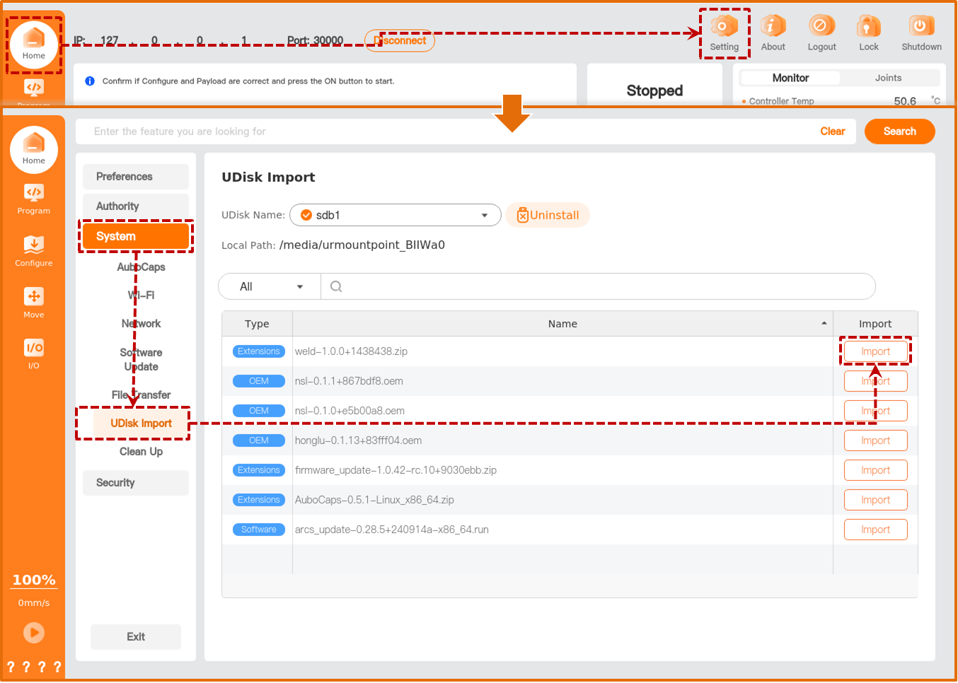
Download the ARCS Welding Process Package from the official website to a USB drive, and insert the USB drive into the USB port of the robot control cabinet.
- Download link: https://download.aubo-robotics.cn/extensions/
Open the teach pendant, tap "Home > Settings > System > USB Import", select the welding process package, and tap [Import].
Tap [Plugins] to enter the [Plugins] interface, tap [Add] at the bottom left of the interface, select the imported welding process package, and confirm the addition.

Set the status button of the "weld" plugin to
 , and tap [Restart] to restart the control cabinet.
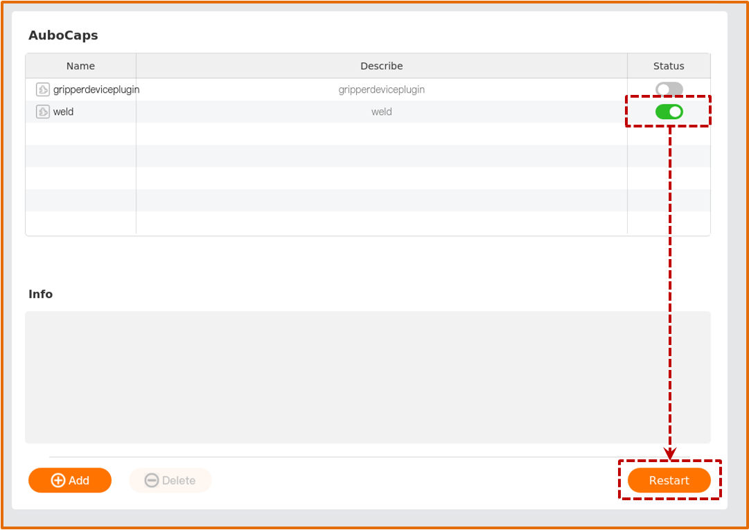
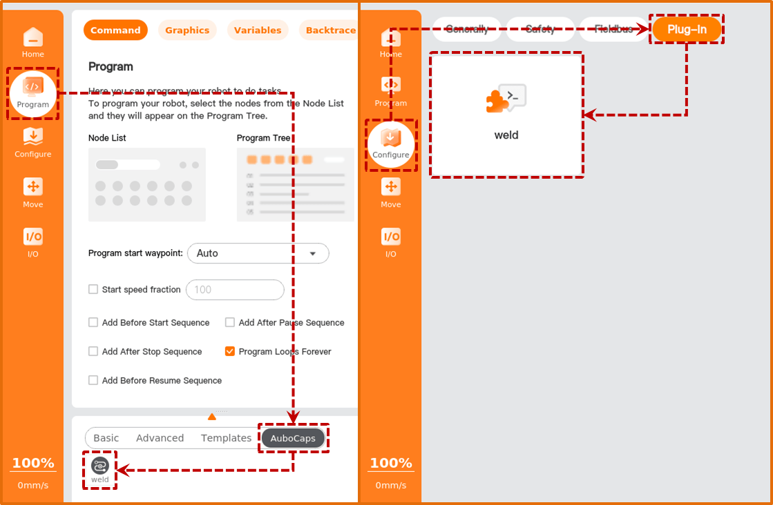
After the control cabinet successfully restarts, you can view the added plugin functions under "Program > Plugins" and "Configure > Plugins".
4 Configuration
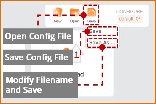
For first-time use or after replacing the welding machine, the parameters of the welding machine and robot, including load, TCP, and the welding machine's communication method, need to be configured. Users can manually configure these functions or import an existing installation configuration file for configuration, as shown in the image below.
注意
- After completing the configuration, save the configuration file first before writing the program file to ensure the settings take effect.
- If the configuration file is modified and is bound to a program file, save the configuration file first and then save the program file to avoid program runtime errors.
4.1 General configuration
4.1.1 Tool center point (TCP)
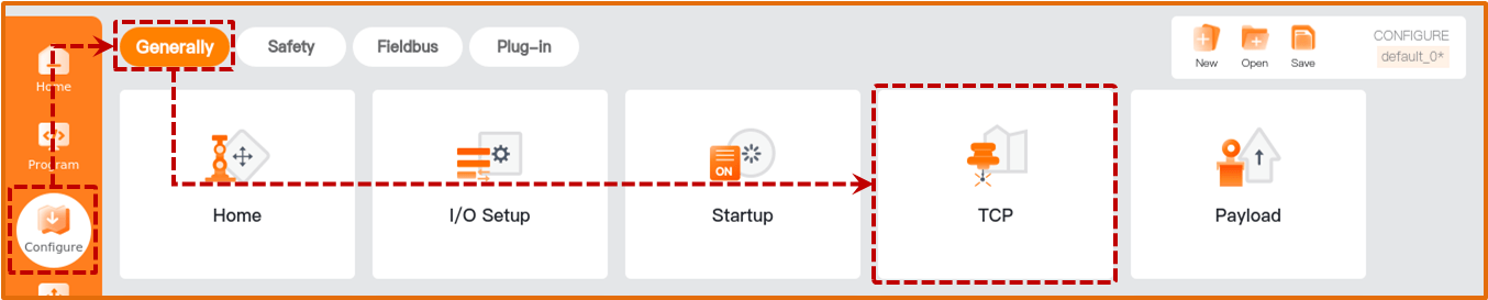
Open the teach pendant and tap “Configure > General > Tool Center Point”.
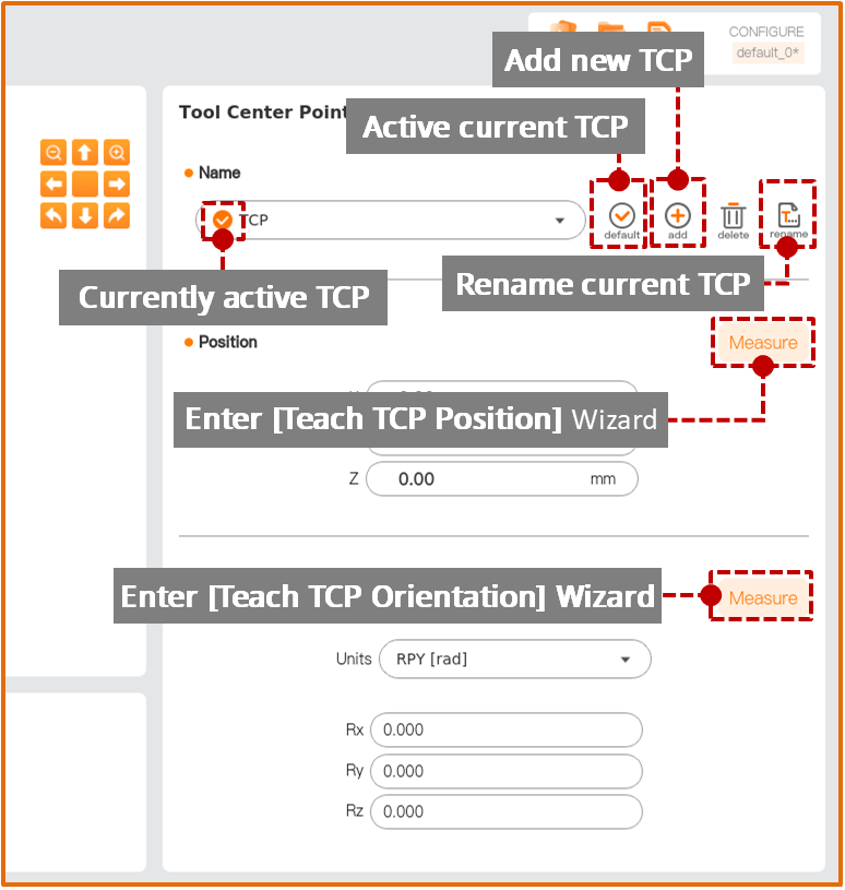
Tap [Add] to create a new TCP, and tap [Rename] to rename the new TCP.
Tap [Position > Measure] to enter the [Teach TCP Position] wizard, and measure the TCP position parameters according to the wizard prompts.
Tap [Orientation > Measure] to enter the [Teach TCP Orientation] wizard, and measure the TCP orientation parameters according to the wizard prompts.
Tap [Default] and then [Save] to apply and save the newly created TCP.
4.1.2 Payload
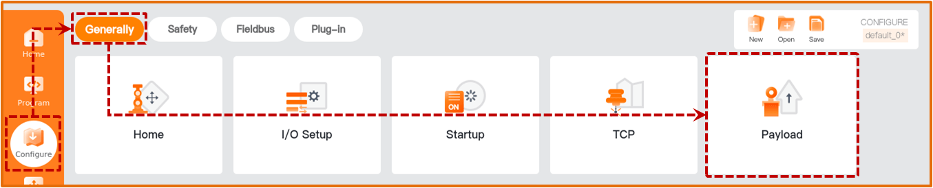
Open the teach pendant and tap “Configure > General > Payload”.
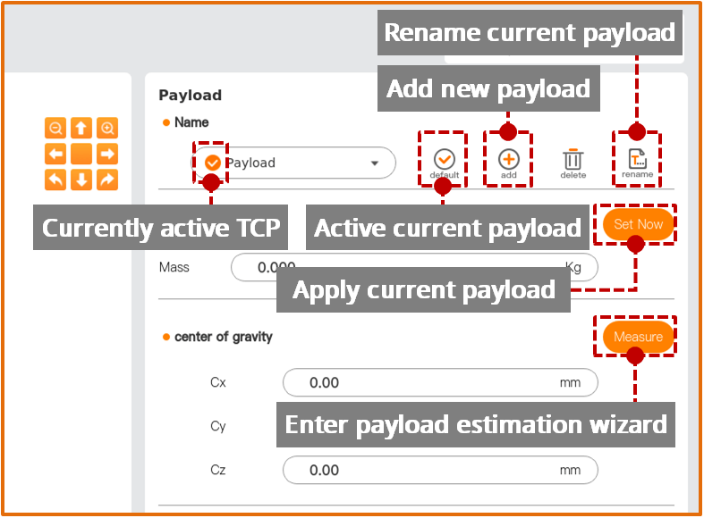
Tap [Add] to create a new payload, and tap [Rename] to rename the new payload.
Tap [Measure] to enter the payload identification wizard, and measure the payload parameters according to the wizard prompts.
Tap [Set Now], [Default], and [Save] to apply and save the newly created payload.
4.2 Welding machine settings
The welder settings should be configured according to the actual welder in use. First, complete the basic settings including Weld Type, Communication, and Weld Machine Type.
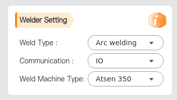
Weld Type: Select the welding type for the welder (arc welding, laser welding, etc.).
Communication: Choose the communication method between the welder and robot (Robot I/O, Modbus, etc.).
Weld Machine Type: Select the welder model.
 : View plugin version information.
4.2.1 Arc Welding Configuration
Select "Arc Welding" for "Weld Type" and complete the following configurations:
Terminal Port Configuration
Under the [Communicate Config] tab, set the relevant parameters according to actual requirements.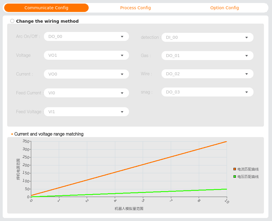
Process Parameter Settings
Under the [Process Config] tab, configure and manage the welding point parameters uniformly.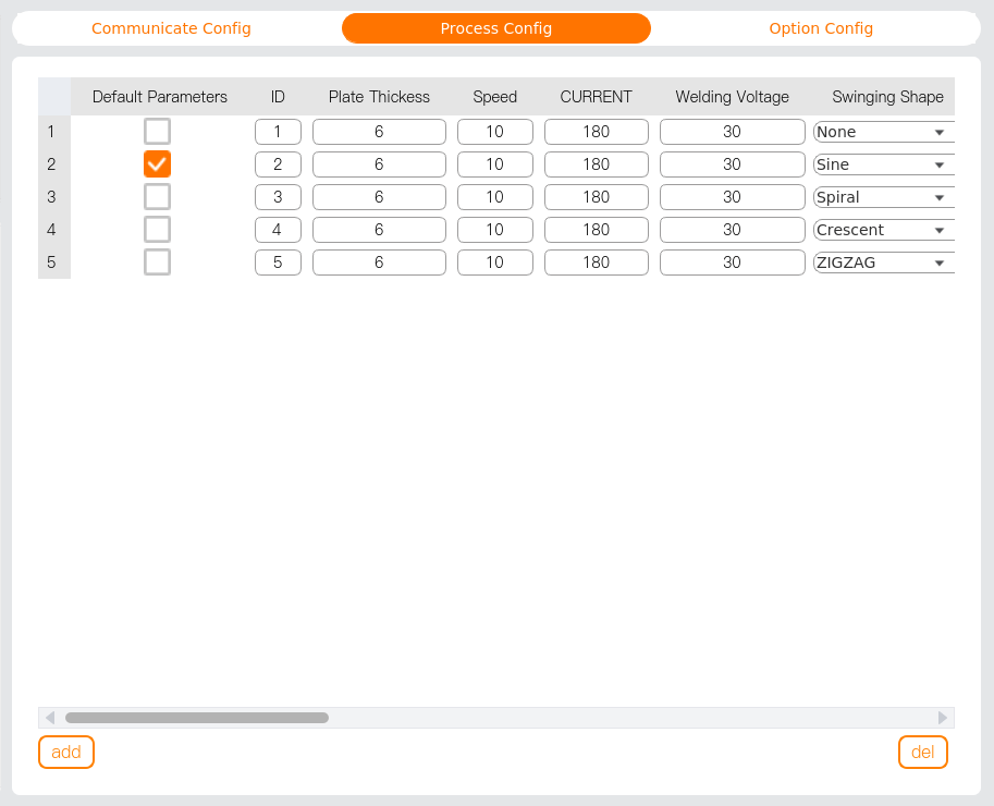
Basic Function Test
In the [Base Function] card, testing functions for arc ignition (ArcStart), gas flow (Gass), wire feeding (Wire), and wire retraction (Snag) are provided. Voltage and current values can be set and monitored.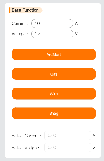
4.2.2 Laser Welding Configuration
Select "Laser Welding" for "Weld Type" and complete the following configurations:
Terminal Port Configuration
Under the [Communicate Config] tab, set the relevant parameters according to actual requirements.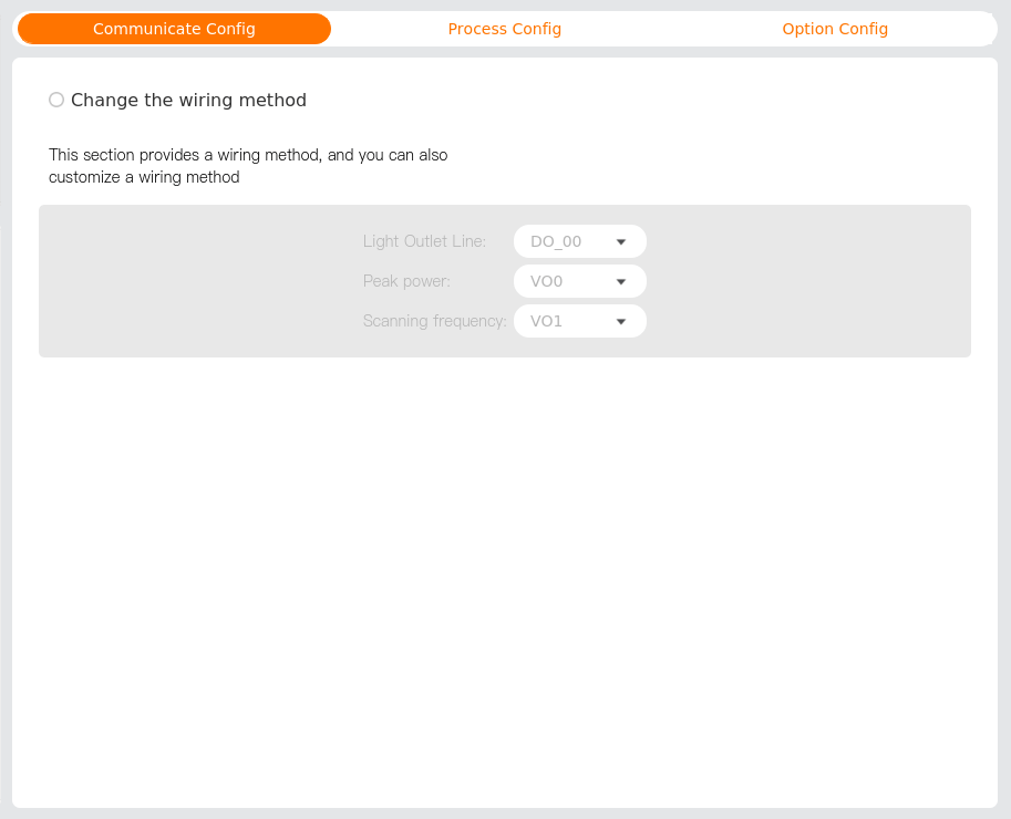
- Light Outlet Line: This I/O port controls the laser output.
- Peak power: This I/O port controls the laser output power.
- Scanning frequency: This I/O port controls the duty cycle.
Process Parameter Settings
Under the [Process Config] tab, configure and manage the welding point parameters uniformly.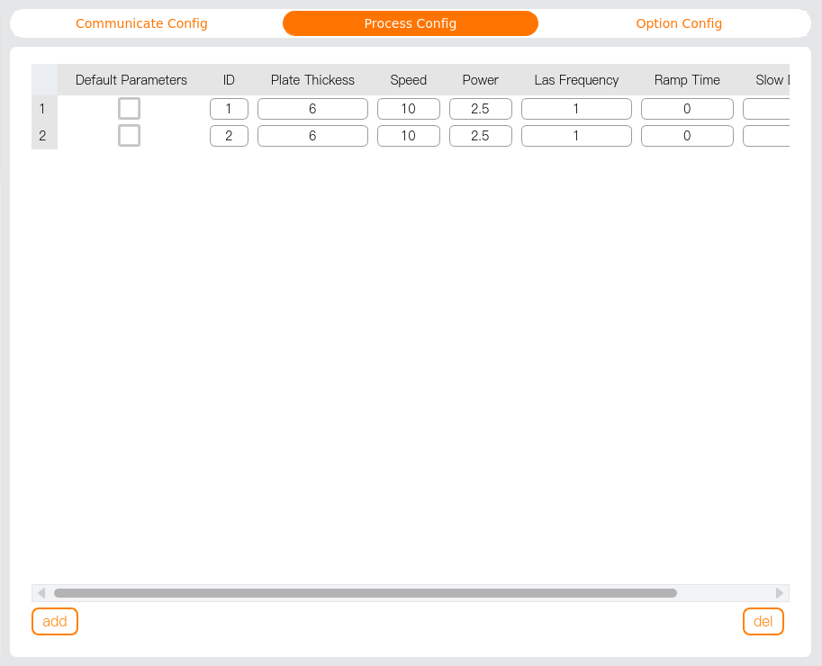
- Ramp Time and Slow Descent Time are in seconds.
Basic Function Test
In the [Base Function] card, testing functions for laser output are provided. The power and frequency of the laser output can be set.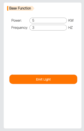
注意
The system provides a 0-10V analog voltage output. Set this analog value before laser output to control the laser output power.
4.3 Optional configuration
4.3.1 Force control
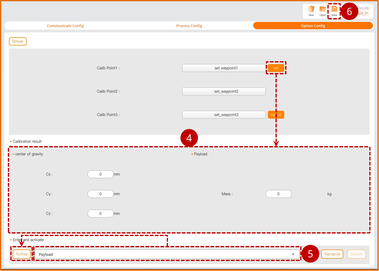
If a six-dimensional force sensor is selected in the hardware configuration, it must be calibrated before use. Follow these steps:
Check “Status” to enable the force sensor, then tap [Configure] to enter the force sensor configuration interface.
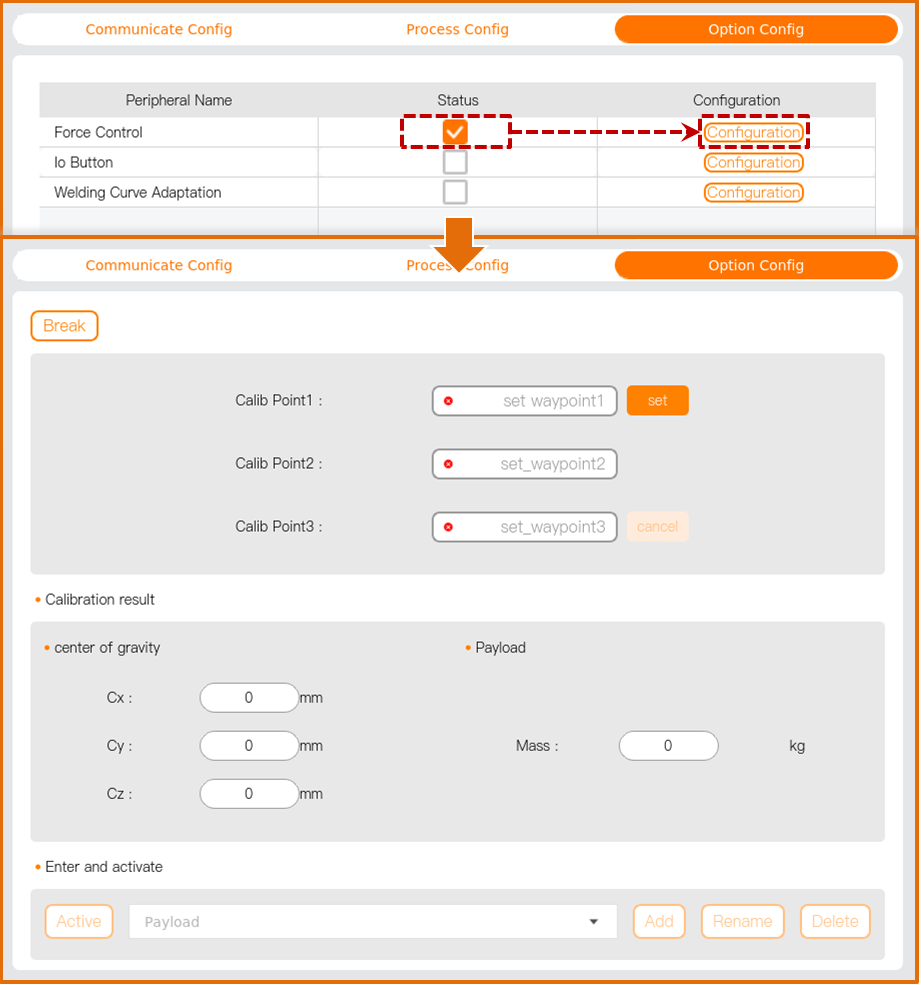
Set Calibration Point 1: Tap [Set Waypoint 1] to enter the [Move] interface, press and hold the [Auto] button to move the robot to the specified position, and tap [Confirm] to exit the [Move] interface.
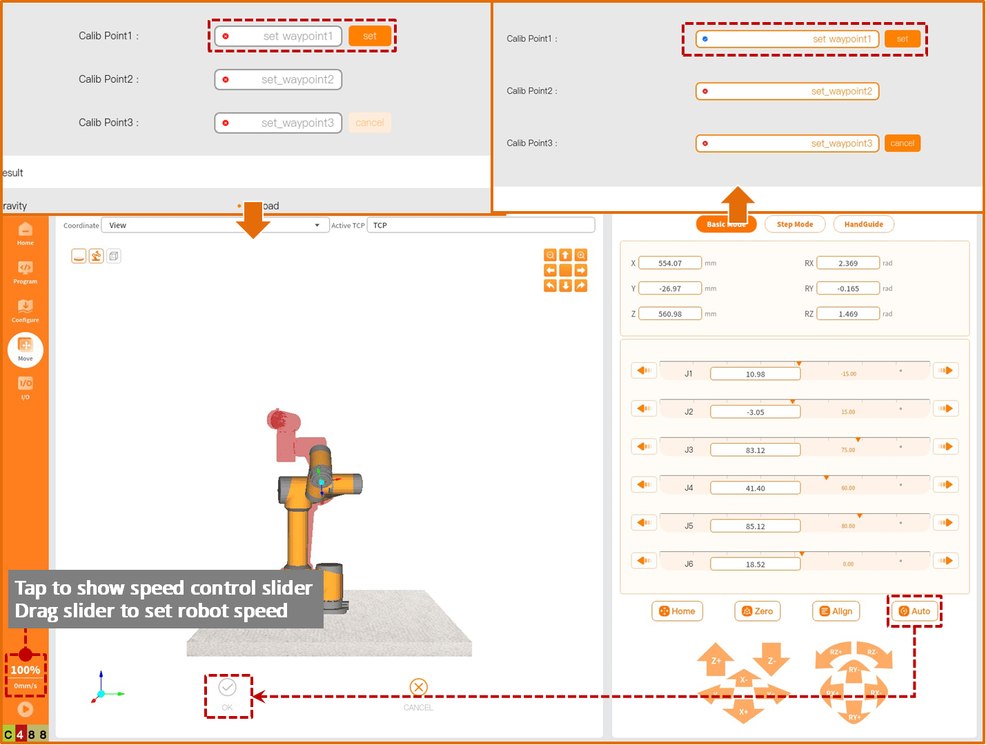
Repeat step 2 to set Calibration Points 2 and 3.
After setting the three calibration points, tap [Set] to view the center of gravity and load applicable to the current force control sensor in the “Calibration Results” section.
In the “Enter and Activate” section, select the load name, tap [Activate] to input the parameters from “Calibration Results” into the selected load and make the load effective.
Tap [Save] to save the current configuration.
4.3.2 IO buttons
If IO buttons are selected in the hardware configuration, configure the IO ports before use. Follow these steps:
Check “Status” to enable the IO buttons, then tap [Configure] to enter the IO button configuration interface.
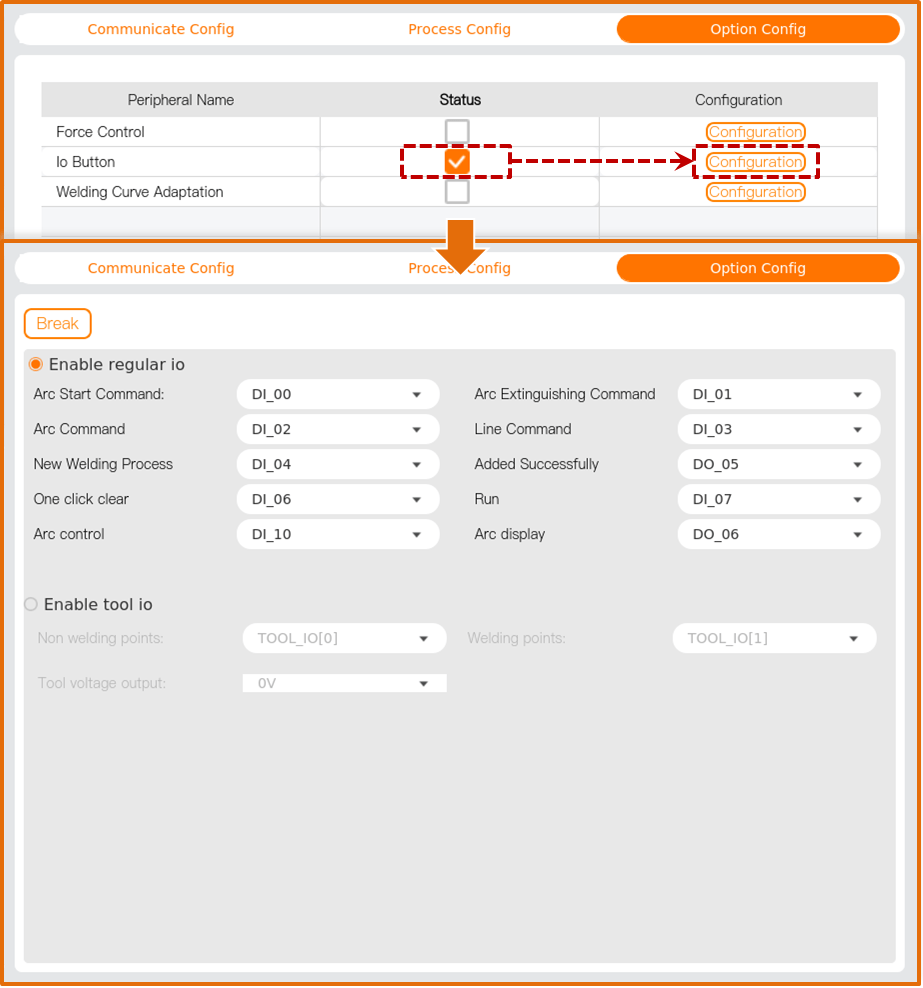
Enable either ordinary IO or tool IO as the button signal port, and then set the IO ports for “Non-Welding Points” and “Welding Points” respectively. If tool IO is enabled, select “24V” for “Tool Voltage Output”.
- “Non-Welding Points” include: Safety Points, Proximity Points, Exit Points.
- “Welding Points” include: Arc Starting Points, Linear Points, Arc Points.
Refer to “5.2 Welding” for instructions on using IO buttons.
5 Program
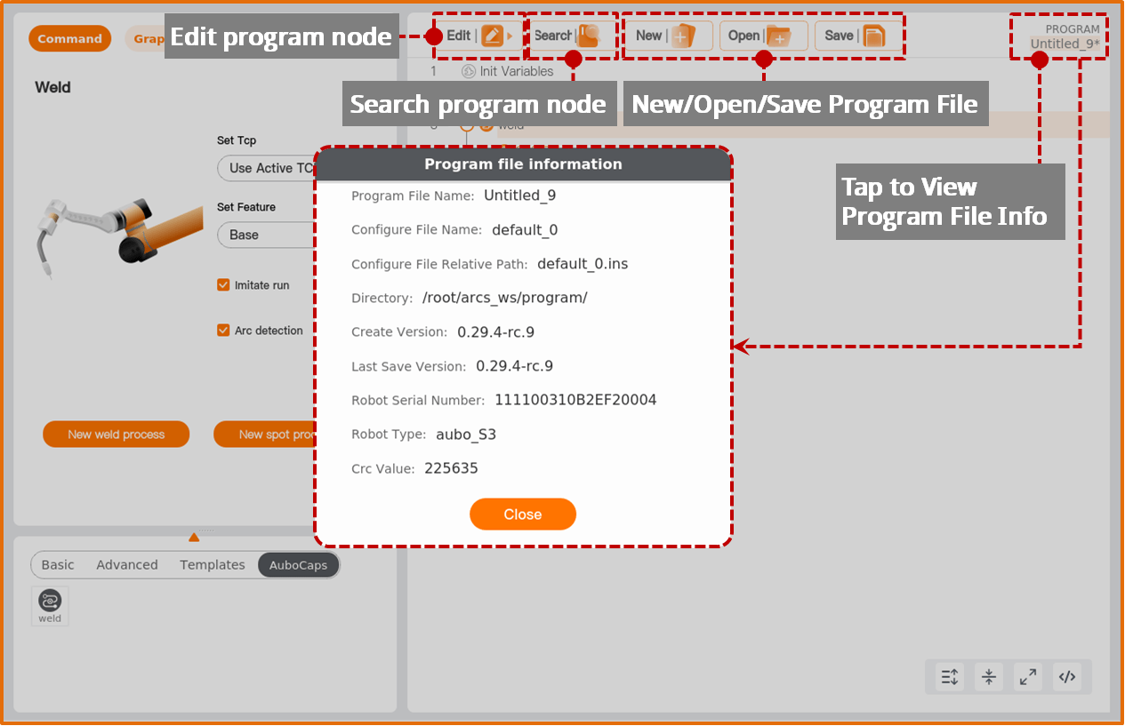
The [Program] interface allows you to create or write robot operation programs. Tap the file name in the top right corner to view detailed information about the current program file.
注意
- After saving a program file, it is bound to the configuration file used during creation. When opening the program file next time, the bound configuration file will be opened simultaneously.
- If the bound configuration file is modified, save the configuration file first, then save the program file to avoid program runtime errors.
5.1 Programming basics
5.1.1 Movement
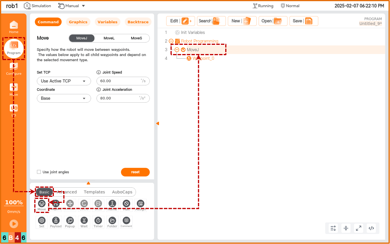
Tap “Program > Basic > Movement” to add a [Movement] node in the program tree. The TCP, coordinate system, joint/tool speed, and joint/tool acceleration set in the [Movement] node are shared parameters for that node.
Set Tool Center Point (TCP): Set the tool center point for the [Waypoint] under this [Movement] node. Choosing different tool center points (TCP) can adjust the robot’s movement between waypoints.
- Use Active TCP: Use the activated TCP.
- Ignore Activated Tool Center Point: Ignore the activated TCP, allowing adjustment of this movement relative to the tool flange.
- Use User-Defined TCP: Use a user-defined TCP.
Coordinate System: Select the default spatial coordinate system for the robot's movement in the welding project.
- When the robot moves, the software calculates the tool center point position based on the coordinates of the selected feature, so choosing different features may result in different robot movement paths.
- The system predefines base and tool features. Users can also define and select custom coordinate systems.
Joint/Tool Speed: When the [Movement] node is “Joint Movement”, set the joint’s movement speed. When the [Movement] node is “Linear Movement”, set the tool’s movement speed.
Joint/Tool Acceleration: When the [Movement] node is “Joint Movement”, set the joint’s movement acceleration. When the [Movement] node is “Linear Movement”, set the tool’s movement acceleration.
Use Blending Radius: When the [Movement] node is “Linear Movement”, set the default blending radius for the [Waypoint] nodes under this [Movement] node.
Use Joint Angles: If checked, the script will record joint angles during program execution, and the system will disable [Set Tool Center Point (TCP)] and [Coordinate System].
Reset: Restore “Joint/Tool Speed”, “Joint/Tool Acceleration”, “Use Blending Radius”, and other parameters to their default values.
Movement types
Robot movement can be categorized into joint movement and linear movement.
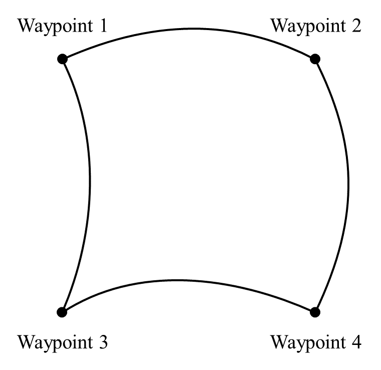
Joint Movement: This involves controlling the robot's joints to achieve its movement. Joint movement provides a curved path for the Tool Center Point (TCP). If you want the robot to move quickly between waypoints without considering the TCP’s path between these points, joint movement is recommended. It is suitable for moving in environments with ample space, and is the fastest way to move. The movement type is shown in the diagram below.
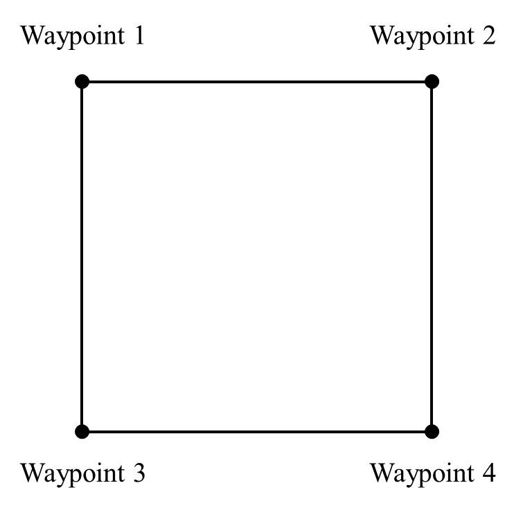
Linear Movement: The robot’s Tool Center Point (TCP) moves linearly to the target waypoint. This means each joint will perform a more complex movement to keep the TCP on a straight path. The tool’s speed can reach and maintain maximum speed depending on linear displacement and maximum acceleration parameters. The movement type is shown in the diagram below.
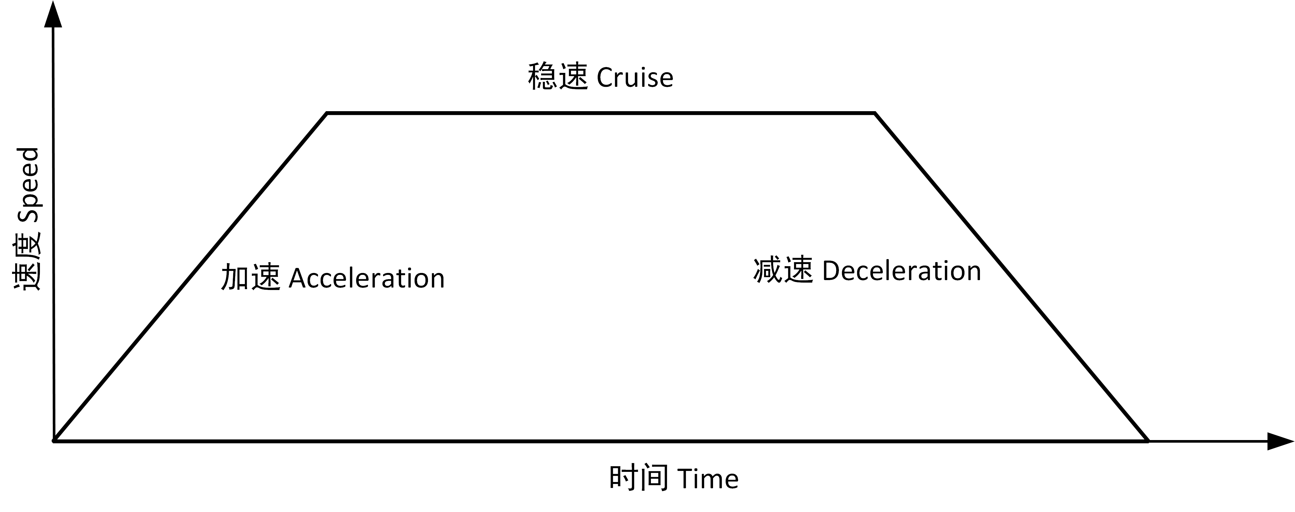
Movement speed
The robot's movement speed curve consists of three segments: acceleration, constant speed, and deceleration. Speed parameters determine the constant speed, while acceleration parameters determine the steepness of acceleration and deceleration, as illustrated below.
Shared parameters
Shared parameters allow for bulk settings of parameters within the program block. For example, after setting the values for [Shared Parameters] in a [Movement] node, any node inserted within the [Movement] program block will default to the values set in the [Movement] node if it uses the parameters included in the [Shared Parameters], unless special settings are made for the parameters in that node.
Adding [Movement] node
- Tap the [Movement] icon to add a [Joint Movement] node in the program tree, which includes a [Waypoint] node below it.
- The [Movement] node includes movement types: joint movement and linear movement. The display name of the [Movement] node in the program tree is determined by the selected movement type.
- Select the [Joint Movement/Linear Movement] node to configure its settings.
5.1.2 Waypoints
The [Waypoint] command is used to set the position points that the robot’s Tool Center Point (TCP) will reach. By setting waypoints, you define the specific positions for robot movement. Typically, the movement path of the robot’s TCP is composed of two or more waypoints. The [Waypoint] node can be configured as [Fixed Position], [Variable Position], or [Relative Position].
Tap “Program > Basic > Waypoint” to add a [Waypoint] node in the program tree.
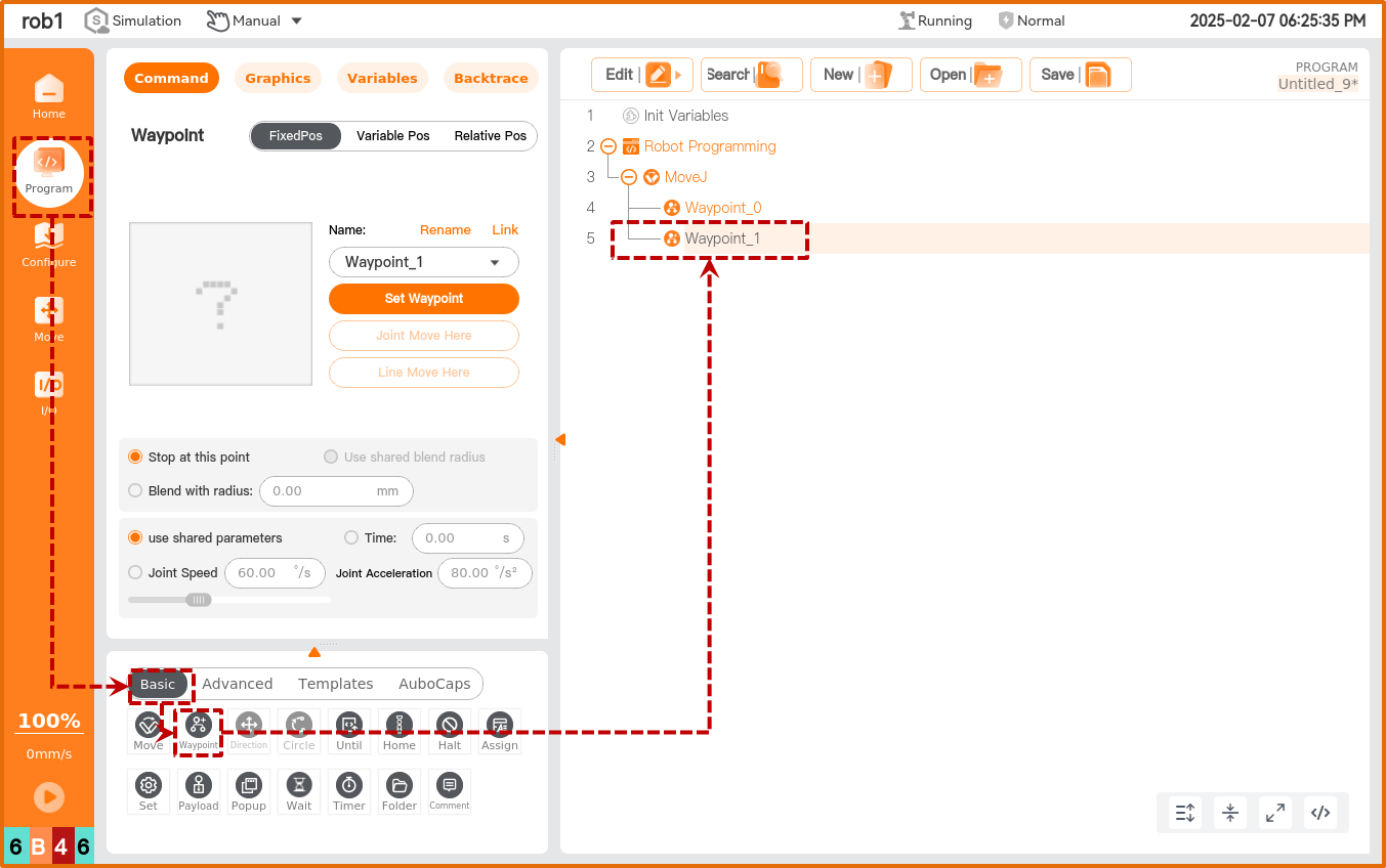
1. Fixed position
[Fixed Position] allows you to set the [Waypoint] pose by operating the robot’s movement interface or dragging the robot.
[Waypoint] Naming and Switching
- Default waypoint name is “Waypoint_n”, where n starts at 0, and each new waypoint increments n by 1.
- Rename Waypoint: Tap [Rename] to modify the waypoint name, but duplicate waypoint names are not supported.
- Link: Tap the
 icon or [Link] to select a waypoint from the program, using the target waypoint’s pose.
Set Waypoint: Tap to enter the [Move] interface and teach the robot the pose of this [Waypoint] node.
Move to Here: Tap to enter the [Move] interface, press and hold the [Auto] button to move the robot’s joints to the pose of the current waypoint.
Linear Move to Here: Tap to enter the [Move] interface, press and hold the [Auto] button to move the robot linearly to the pose of the current waypoint.
Blending Parameters
- Stop at this Point: The robot will briefly pause at this point before moving to the next waypoint.
- Blending Radius: When the robot moves into the blending radius range, it will start to smoothly transition between the two trajectories.
Movement Parameters
- Use Shared Parameters: Use the parameters set within the [Movement] node.
- Time: Set the total move time from the previous waypoint to this waypoint (unit: s). This setting will affect the robot’s speed. An unreasonable total move time may cause the robot's movement parameters to exceed its parameter range; the system will optimize this, so refer to the parameters during robot operation.
- Joint/Tool Speed: Set the movement speed of the joint/tool.
- Joint/Tool Acceleration: Set the movement acceleration of the joint/tool.
2. Variable position
[Variable Position] allows setting the [Waypoint] pose through variable configuration. [Variable Position] is commonly used to batch change parameters of similar waypoints, saving programming time.
- Use Variable: Tap the [Use Variable] dropdown to select a variable. Refer to “4.3.6 Assignment” and “5.1.7 Variables” for variable settings.
- Variable Type: Set the type of the variable.
- Pose Type: The six parameters of the variable correspond to six joint angles, with angles in radians. For example:
i_variable_1= {0, -0.261796, 1.74532, 0.436316, 1.5708, 0}. - Joint Type: The six parameters of the variable represent the robot’s pose, with units in
m. For example:i_variable_1={0.548871, -0.1215, 0.263199, 3.14159, 0, 1.5708}.
- Pose Type: The six parameters of the variable correspond to six joint angles, with angles in radians. For example:
3. Relative position
[Relative Position] defines the [Waypoint] pose based on the difference between two given positions (source waypoint, target waypoint). At least one [Fixed Position] waypoint or [Variable Position] waypoint must precede the [Relative Position] waypoint; otherwise, the robot may encounter unpredictable errors.
- Distance: Refers to the Cartesian distance between the source waypoint and the target waypoint.
- Angle: Refers to the length of the rotation vector of the direction change between the source waypoint and the target waypoint.
- [Waypoint] Renaming and Selection: Tap [Rename] or the waypoint name to rename the source waypoint or target waypoint.
- Tap [Link] or the icon to expand the waypoint list and select a waypoint.
- Set Source Waypoint, Set Target Waypoint: Tap to switch to the robot teaching interface, use the [Position/Attitude Control Buttons] to move the robot, or use the teaching mode to manually move the robot to the target waypoint. After setting, tap [Confirm] to save the pose of the source waypoint or target waypoint.
- Move to Here: Tap to switch to the [Move] interface, press and hold [Auto] to move the robot to the pose of the waypoint.
5.2 Welding
Tap “Program > Plugins > Welding” to add a [Welding] node in the program tree.
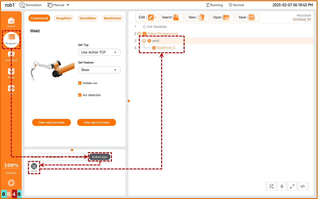
Set Tool Center Point (TCP): Selecting different Tool Center Points (TCP) adjusts how the robot moves between waypoints.
- Use Active TCP: Use the active TCP.
- Ignore Active Tool Center Point: Ignore the active TCP, allowing movement relative to the tool flange.
- Use User-defined TCP: Use a user-defined TCP.
Feature: Choose the default spatial coordinate system for the robot's movement during the welding project.
- During robot movement, the software calculates the position of the Tool Center Point as coordinates of the selected feature, so different features may lead to different robot movement trajectories.
- The system has predefined base and tool features. Users can also select custom coordinate systems.
Simulation Run: Check this option to run the entire project without starting an arc, to test if the written program meets expectations.
- During simulation, gas and wire will be fed in advance, but no arc will be started.
- After confirming the simulation run meets expectations, uncheck [Simulation Run] to perform actual welding operations.
Add Linear/Arc State: If IO buttons are configured, this button can be used to set a new linear (linear) node or arc node when the “Welding Point” IO button is pressed.
- IO button configuration is described in “4.5.2 IO Buttons”.
- IO Button Usage:
- Select the [Welding] node; by default, the button for adding nodes is automatically enabled.
- Tap “Non-welding Point” or “Welding Point” buttons in sequence and their corresponding functions are as follows:
- The first tap of the “Non-welding Point” button assigns the current robotic arm pose to the [Safety Point] node.
- The second tap of the “Non-welding Point” button creates a new project.
- The third tap of the “Non-welding Point” button assigns the current robotic arm pose to the [Proximal Point] node.
- Subsequent clicks of the “Non-welding Point” button will create a new [Proximal Point] node and assign values.
- Tapping the “Welding Point” button assigns the current robotic arm pose to the [Start Arc Point] node.
- The second tap of the “Welding Point” button creates a new [Linear Point] or [Arc Point] node and assigns values. Tapping the “Welding Point” button again creates another [Linear Point] or [Arc Point] node and assigns values.
- Tapping the “Non-welding Point” button assigns values to the [Exit Point] node. Tapping the “Non-welding Point” button again creates a new [Exit Point] node and assigns values.
Create New Project: Create a new welding project. For details, refer to “5.3 Create New Project”.
Create Spot Welding Project: Create a new spot welding project. For details, refer to “5.4 Create Spot Welding Project”.
5.3 Create new project
Actual starting and stopping of the arc are performed within welding projects. Each welding project can have multiple welding processes, and different welding projects can be configured with different welding parameters (such as weaving welding).
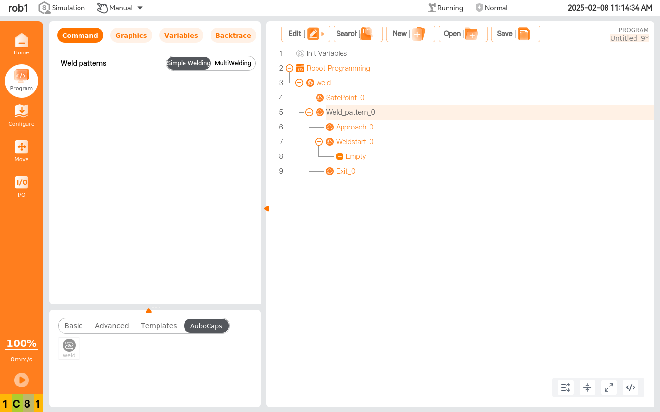
- Safety Point: The point where the welding program begins preparation.
- Proximal Point: Each welding process includes a proximal point, used to avoid obstacles between the start arc point of the small segment of welding.
- Start Arc Point: The point where the welding machine will actually start the arc during the entire welding process.
- Linear: Add a [Linear] node in the current welding process.
- Arc: Add an [Arc] node in the current welding process.
- Interrupt Point: Add an [Interrupt] node in the current welding process.
- Exit Point: Waypoints used to leave the welding area, multiple can be established.
5.4 Create spot welding project
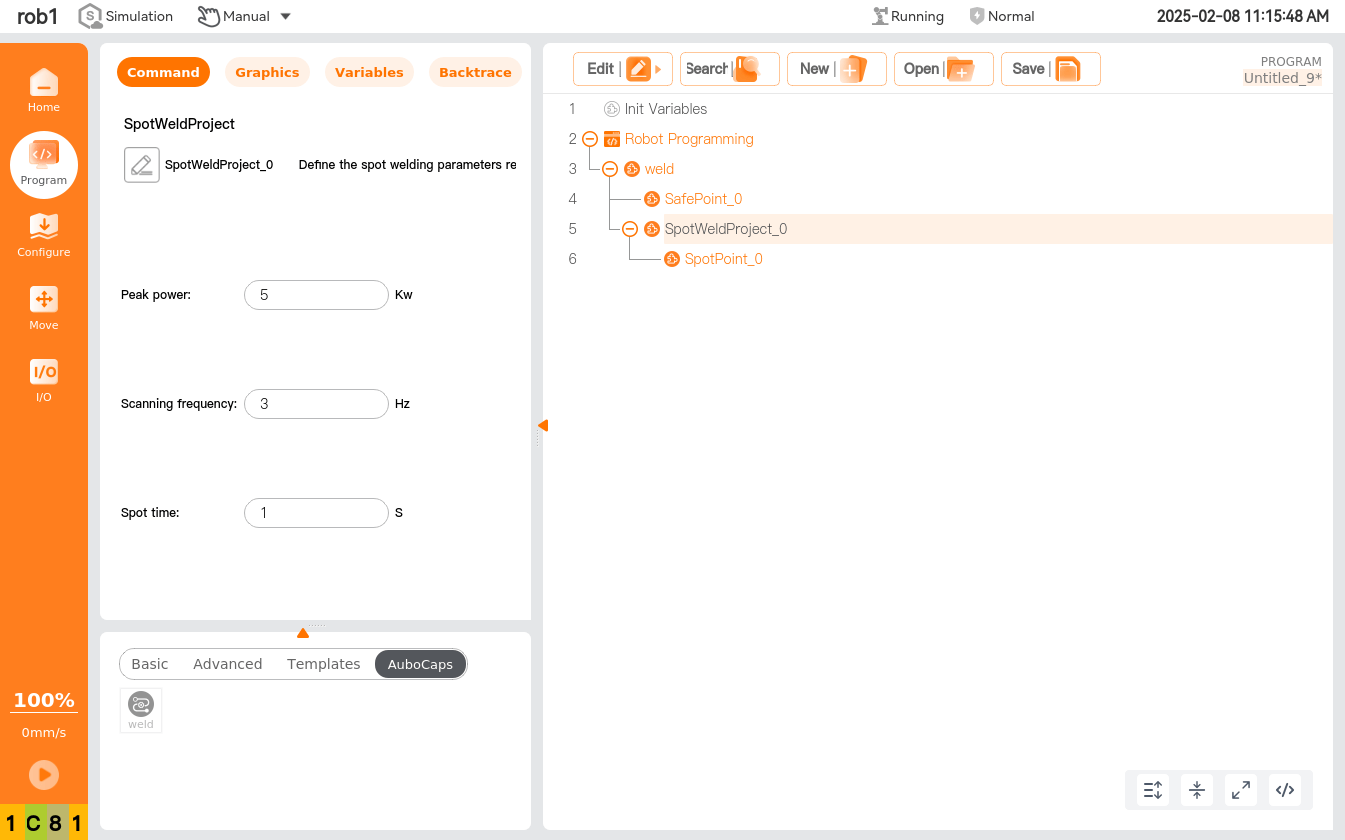
- Spot Welding Project
 : Rename the spot welding project name.
- Set Current: Set the given current for the spot welding project.
- Set Voltage: Set the given voltage for the spot welding project.
- Spot Welding Time: Set the welding time for the [Spot Welding] node under this spot welding project.
- Spot Welding: Add a [Spot Welding] node in the current welding process.
- Transition Point: Add a [Transition Point] node in the current welding process.
6 Practical Examples
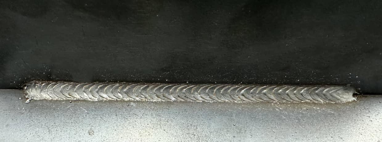
6.1 Linear segment example
Program Example
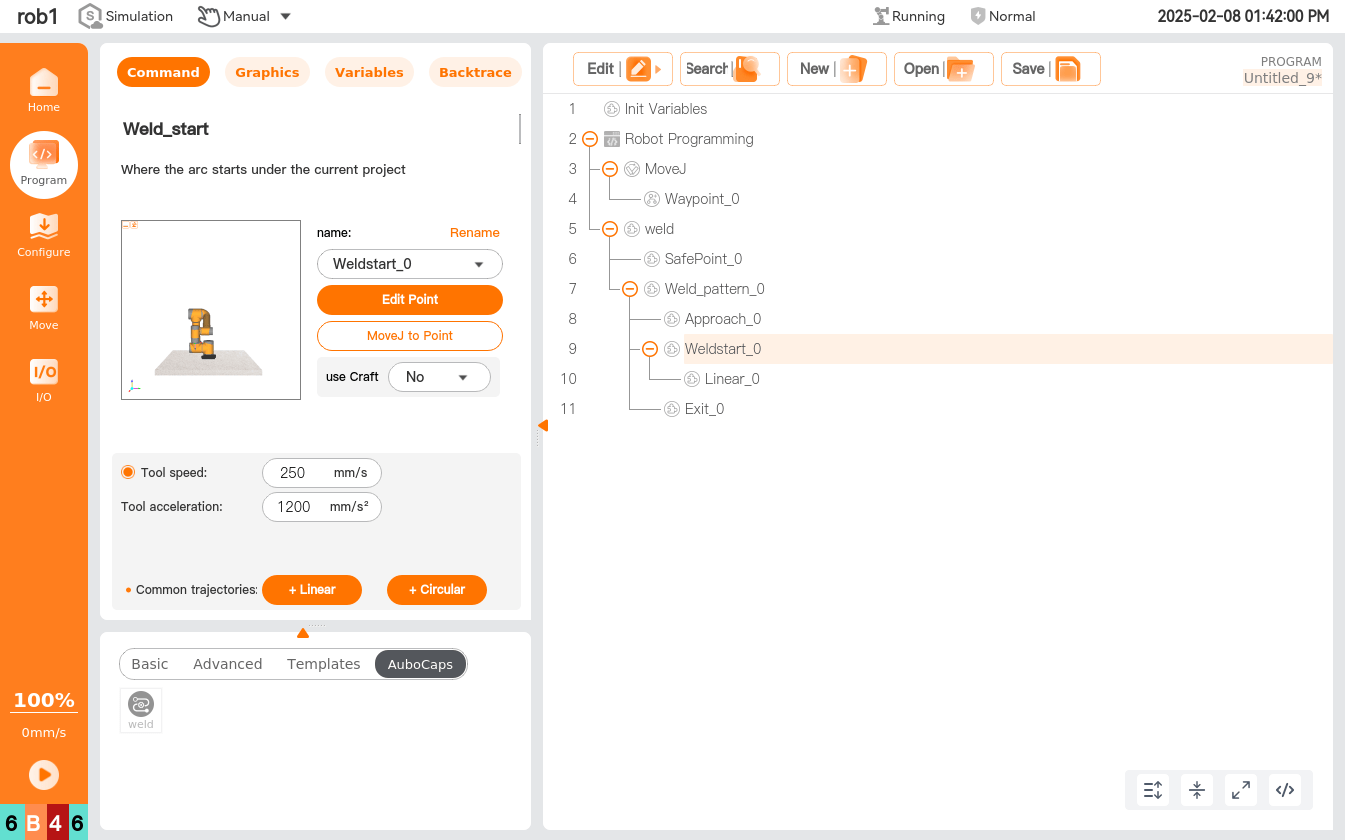
Welding Effect
6.2 Semi-circle example
Program Example
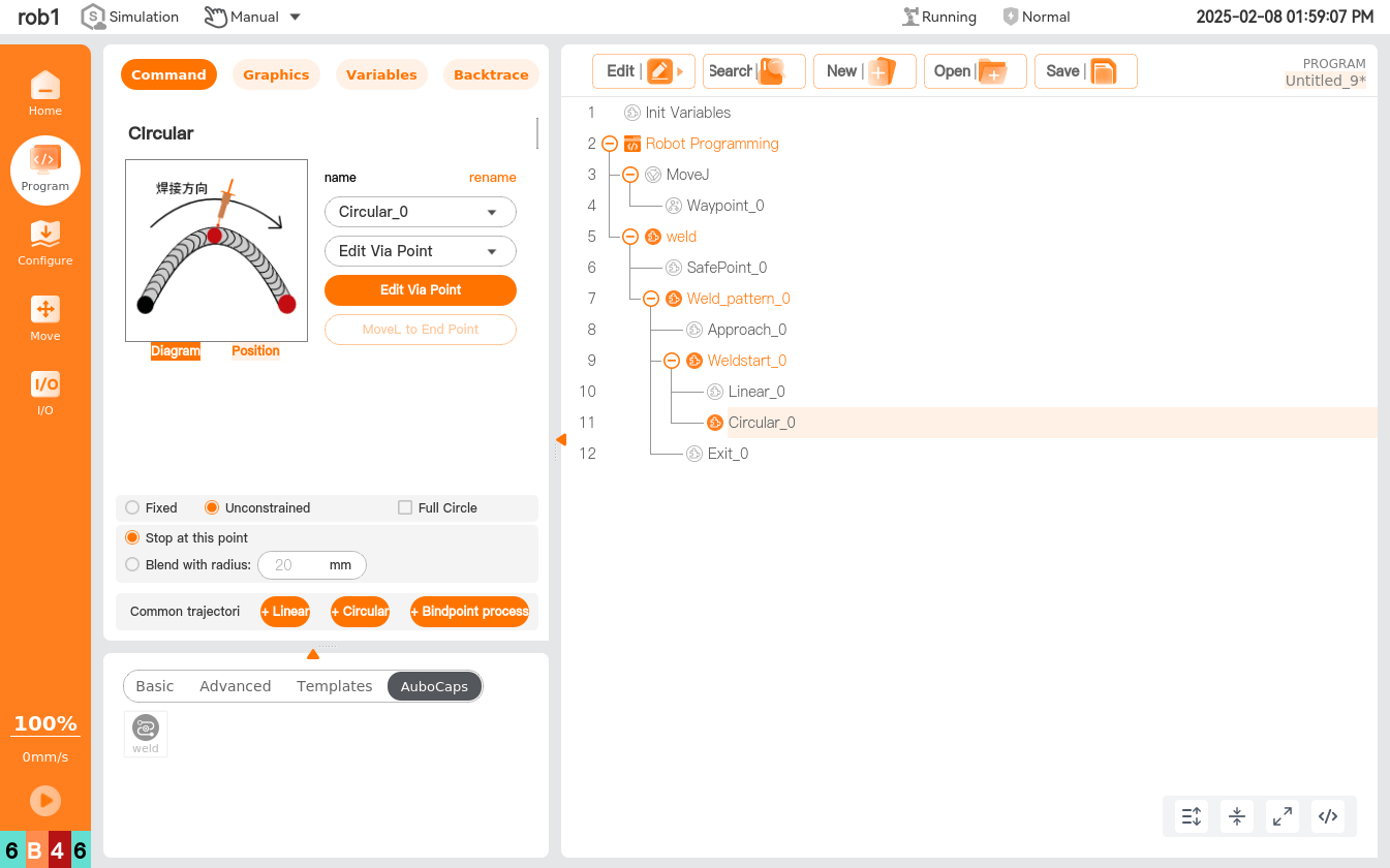
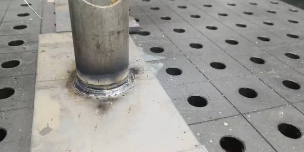
6.3 Full circle example
Program Example

Welding Effect
Version History
v1.1.0 (2025/01/22)
Changes
[New Features]
- [4.2 Welder machine settings] Added arc welding and laser welding configuration instructions.