Industrial Bus Application Manual
1. Preface
This manual is intended for technical personnel engaged in design, debugging, operation and maintenance, and selection in the field of industrial automation. It systematically organizes the core knowledge system of three mainstream industrial buses: EIP (including soft EIP), Modbus, and Profinet. The content balances theoretical foundations with practical implementation, covering technical principles, hardware selection, configuration and debugging, troubleshooting, and scenario adaptation. It not only meets the needs of beginners for quick entry but also provides accurate references for senior engineers.
2. Security Information
Due to the potential risks involved in industrial bus systems, such as electrical connections and equipment linkage, users must carefully read, understand, and comply with the instructions in this manual before use.
Integrators must ensure that the deployed bus systems comply with relevant laws, regulations, and industry standards, strictly conduct risk assessments, and take necessary measures to reduce risks. At the same time, users must abide by the safety specifications designated by integrators.
AUBO WARNING
When deploying and using industrial bus systems, attention must be paid to equipment and operational safety. Users of the bus system are responsible for their own safety and on-site safety. AUBO shall not be liable for safety issues caused by illegal operations or failure to comply with safety regulations.
3. Fundamentals of Industrial Bus Technology
3.1 Overview of Industrial Bus
Industrial bus is a communication network that connects industrial automation equipment, used to realize data exchange and control command transmission between devices. In modern industrial automation systems, industrial bus plays a crucial role, as it is the foundation for achieving device interconnection, data collection, and real-time control.
3.2 Comparison of mainstream industrial buses
| Bus type | communication rate | real-time performance | Network topology | Applicable scenarios | Advantage | Disadvantage |
|---|---|---|---|---|---|---|
| Profinet | 100Mbps/1Gbps | High (millisecond level) | Star-shaped | Complex automated systems | Good real-time performance and rich functions | Complex configuration |
| Modbus | 9.6Kbps-10Mbps | middle | Bus/Star | Simple control system | The protocol is simple and easy to implement. | Real-time performance is average |
| EIP | 100Mbps/1Gbps | High (millisecond level) | Star-shaped | Integration of multi-vendor devices | Good openness and strong compatibility | Complex configuration |
3.3 Guide for Selecting Bus Technology
When selecting an industrial bus, the following factors should be considered:
- Application scenario: Select an appropriate bus based on system complexity and real-time requirements.
- Device compatibility: Ensure that the selected bus is compatible with existing devices.
- Network scale: Select a bus that supports the corresponding scale according to the number of nodes.
- Communication distance: Consider the physical distance between devices.
- Cost Budget: Including hardware, software, and maintenance costs.
- Technical Support: Consider the technical support capabilities of the supplier.
3.4 Network Basics and Hardware Preparation
3.4.1 Network topology design
Common industrial network topologies include:
- Star topology: All devices are connected through a switch, with high reliability and easy maintenance.
- Bus topology: Devices are connected via a single bus, with low cost and suitability for small-scale systems.
- Ring topology: Devices form a ring, with redundancy function and high reliability.
3.4.2 Selection of hardware devices
- Switch: Select an industrial-grade switch that supports the required bandwidth and number of ports.
- Network cable: Use shielded twisted pair (STP) to ensure the quality of signal transmission.
- Connector: Industrial-grade connectors are used to ensure connection reliability.
- Network Tester: Used for network fault diagnosis.
3.4.3 Hardware Wiring Specifications
- Follow the wiring standards recommended by the manufacturer.
- Ensure good grounding to reduce electromagnetic interference.
- Avoid parallel routing with power cables.
- Check regularly for loose connections.
3.5 General configuration process
3.5.1 IP address planning
- Assign a static IP address to the device to avoid IP conflicts.
- Using reasonable subnet division facilitates network management.
- Record the IP addresses of all devices and establish a network topology map.
3.5.2 Firewall settings
- Ensure that the firewall allows the ports required for bus communication.
- Configure appropriate access control rules.
- Update firewall rules regularly.
3.5.3 Communication test method
- Use the ping command to test network connectivity.
- Test the bus communication quality using dedicated tools.
- Perform load testing to ensure that the system operates normally under peak load.
4. Profinet Slave User Guide
4.1 Quick Start Guide
The Profinet slave is the soft protocol stack Profinet. This chapter will help you quickly get started with Profinet slave configuration, providing one-stop configuration guidance from environment preparation to communication testing.
4.2 Environmental preparation for Profinet configuration
4.2.1 Environmental preparation
- Software preparation:
- ARCS software versions V0.29.5-rc.22, 0.31.0-rc.27 and later, have been integrated into the ARCS software, so there is no need for manual installation anymore.
- Previous software versions required manual installation of the Profinet plug-in. If you need to update the plug-in version, please contact AUBO customer support.
- Software installation:
- Click Data Package to get the Profinet plugin zip package.
- Find the GDS file (device description file) in the data package: gsdml-v2.31-arcs-ICM-20240529.xml.
- Please visit the official page of Siemens S7-200 SMART,and install the STEP 7 debugging software.
- Hardware preparation: Siemens
s7-200 smart, robot arm body, laptop, network cable, HUB or switch.
4.2.2 Hardware wiring
Connect the PLC, the controller and the local computer to the same network through the switch.
4.2.3 Profinet software installation and configuration
Versions V0.29.5-rc.22 and versions after 0.31.0-rc.27 have the pn soft protocol stack built-in, so there is no need to install it manually.
Previous software versions required manual installation of the pn soft protocol stack.
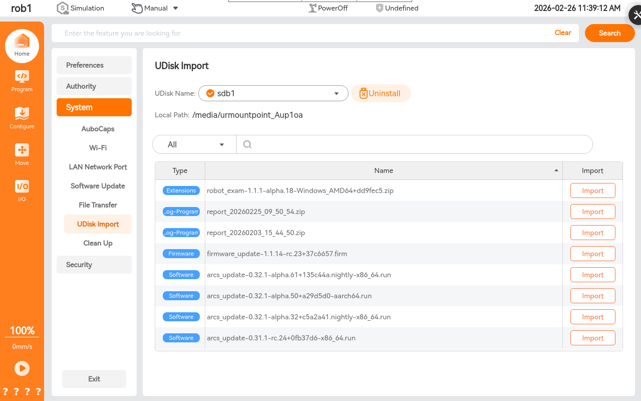
Use a USB drive to copy the required files, and place the following files in the root directory:
- pn_server-x.x.x.run
- aubo_magic_pn_server_install_v1.0_20240422.sh
Use the ARCS software, click "Settings > System > USB Drive Import" to import
pn_server-xxxx.runinto the control cabinet, and execute the shell script.
4.3 Profinet software test and verification
4.3.1 Opening Profinet slave
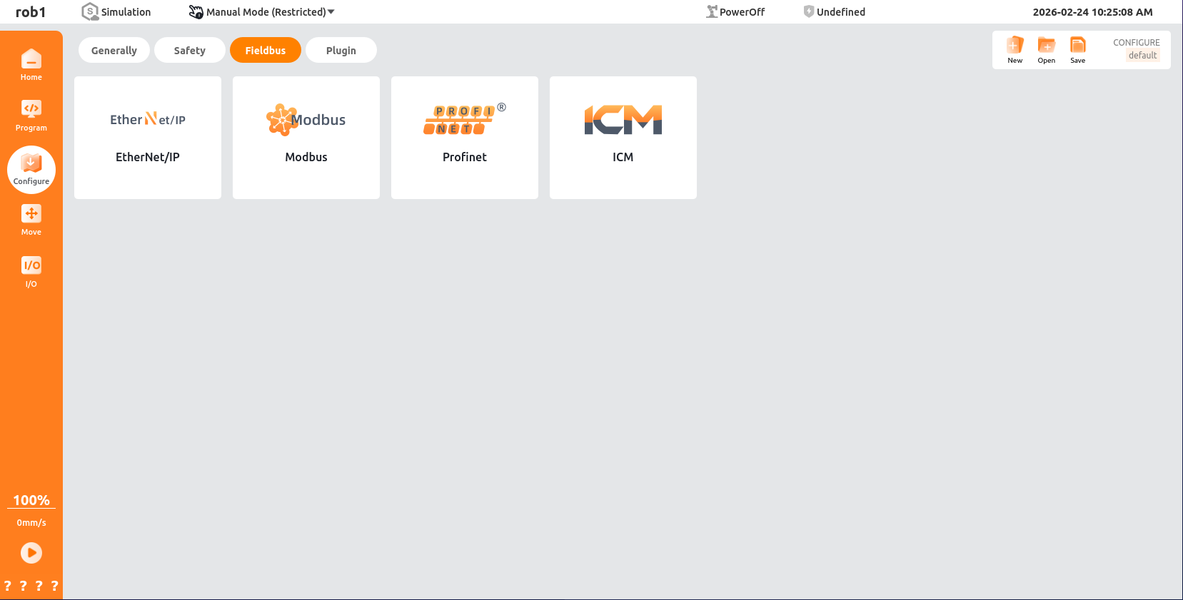
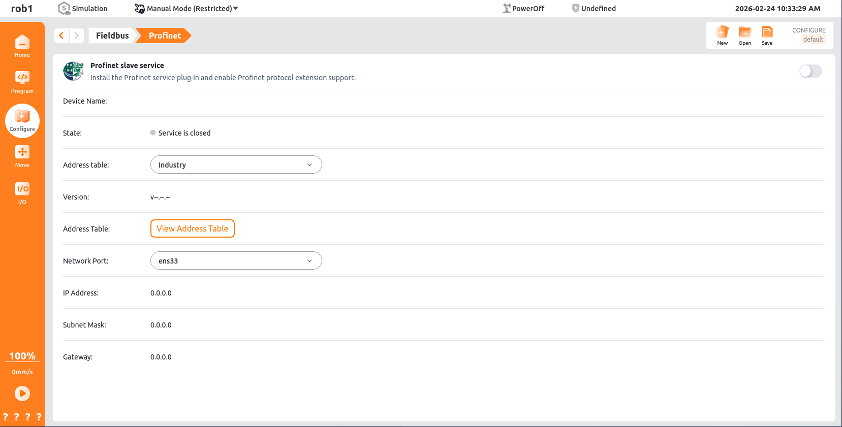
Open the homepage of the ARCS software, click "Configuration > Fieldbus > Profinet" in the left navigation bar to open the Profinet Slave Station.
4.3.2 Connecting PLC to Profinet Slave
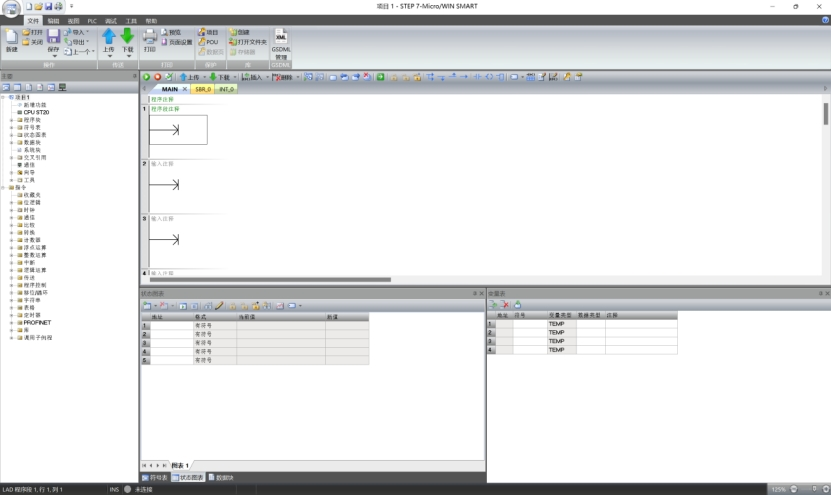
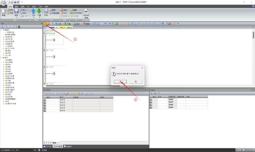
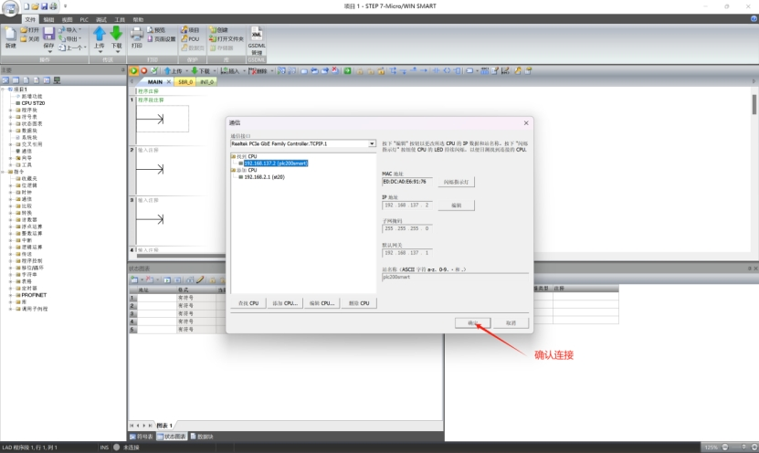
For the purpose of this Guide, s7-200 smart plc (hereinafter referred to as PLC) is taken as an example for explanation.This PLC is programmed with STEP-7 Micro/WIN SMART.
The interface of this software is shown in the following figure:
Set the CPU of the PLC to RUN mode.
Check the PLC IP address.
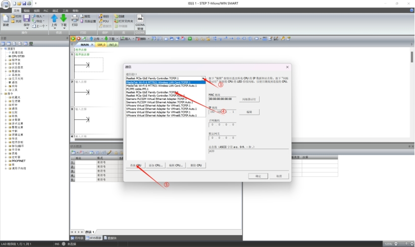
To connect to the PLC, configure the computer’s IP address to a fixed address on the same LAN.
Note:
In this tutorial, the PLC IP is
192.168.137.2, connected to a PCIe wired adapter.Set this adapter’s IP to
192.168.137.X, where X = 1–255 (not the same as the PLC IP).On the computer, press
Win + R, typencpa.cpl, and pressEnterto open network connection settings. Right-click Ethernet and select Properties.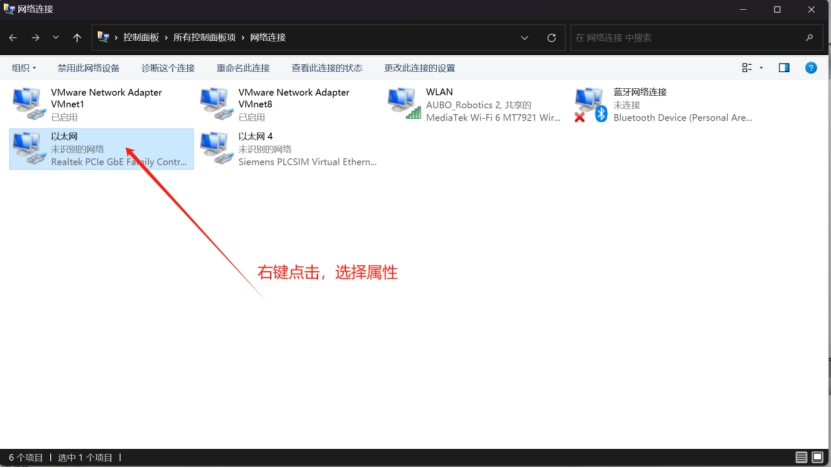
Select [Internet Protocol Version 4 (TCP/IPv4)] and click [Properties].
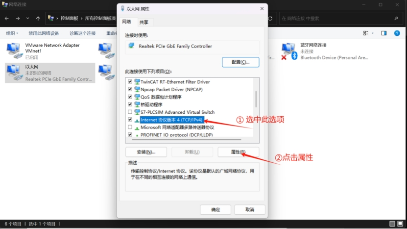
Set the IP address of the network adapter.
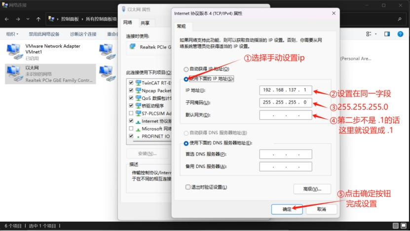
After configuration, the PLC and computer will be on the same network segment and can connect normally.
Warning
- PLC IP configuration must be based on an established device communication link.
- A communication link between a PLC and a host computer requires both to be on the same IP subnet (network segment).
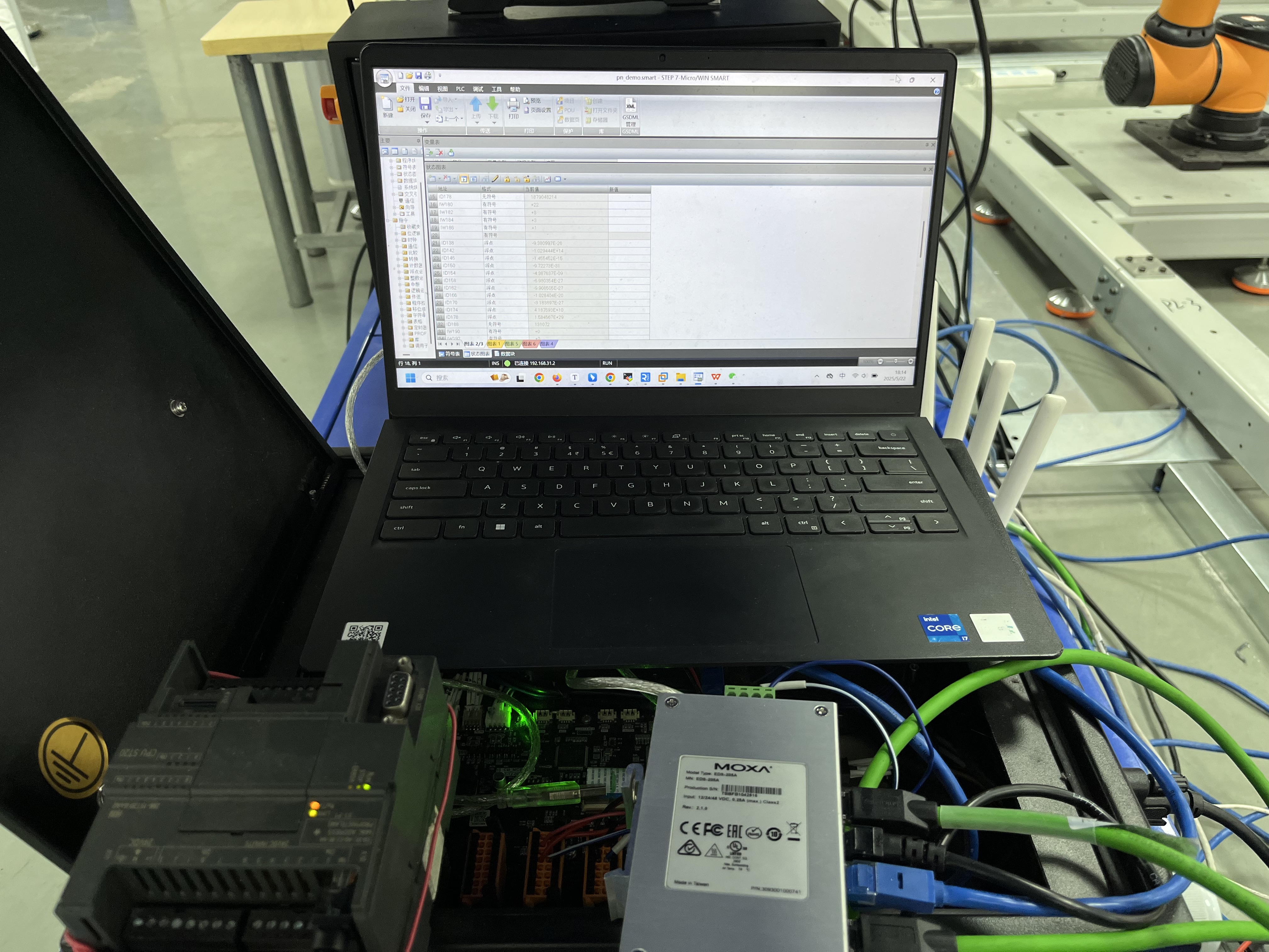
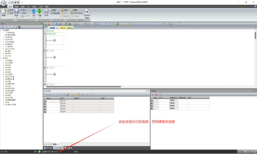
The status after connection is as follows:
4.3.3 Configuration Engineering
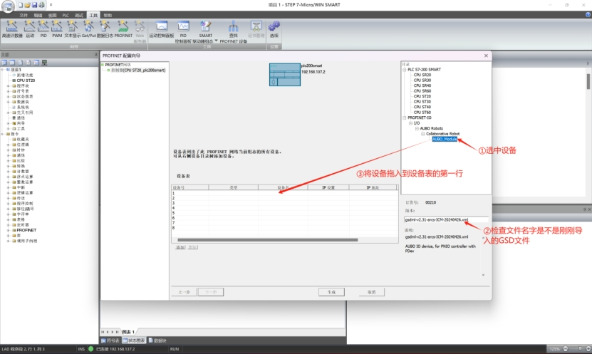
Import the GSD file from the resource package downloaded in 4.2.1 Environment Preparation.
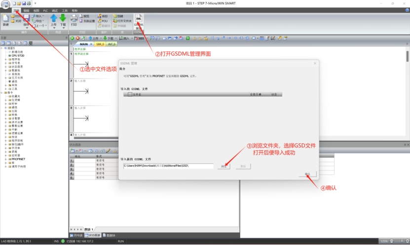
Configure the Profinet test project.
Note
The Profinet test project is a systematic verification method for the Profinet communication architecture.
It is a pre-verification step to ensure reliable operation of the industrial communication layer, used to:
- Verify device protocol compliance and interoperability
- Test network real-time performance and stability
- Validate configuration validity
Configure the parameters of the PLC as an IO controller in Profinet communication.
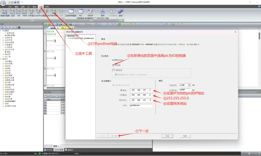
Configure Profinet devices.
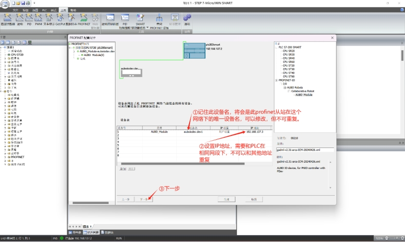
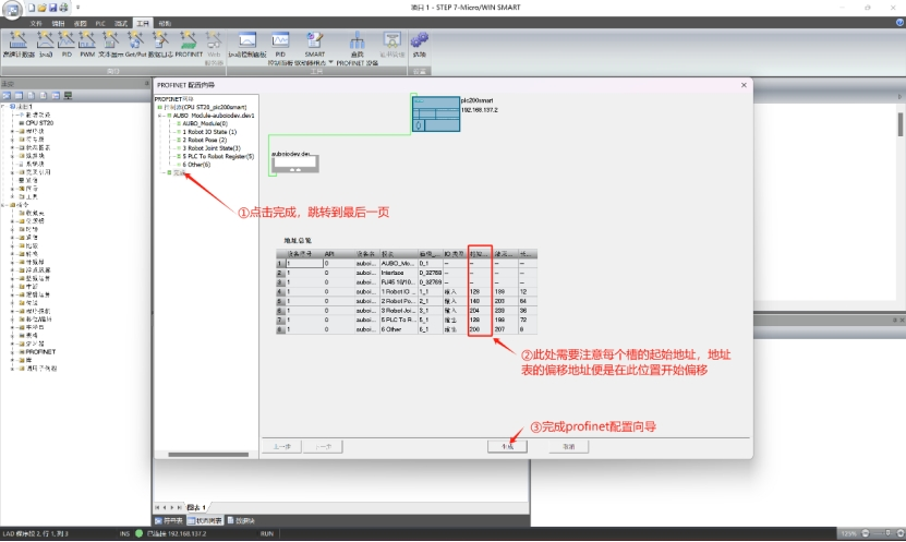
Record the Profinet slave device name and set the device IP address (in the same network segment as the PLC and not duplicated).
Drag the target module into the Profinet communication slot and select the data refresh cycle.
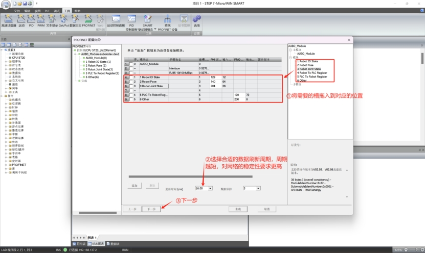
Click [Finish] to jump to the page, check the starting address of the slot, and then complete the Profinet configuration.
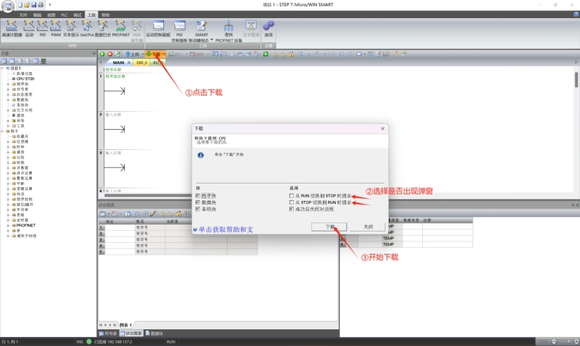
Save the project, click Download, and download this project to the PLC.
Note
- The PLC-side Profinet configuration wizard has been completed and downloaded successfully, and the robot's Profinet slave function is now enabled.
- The robot, PLC, and host computer are on the same LAN and share the same network segment.
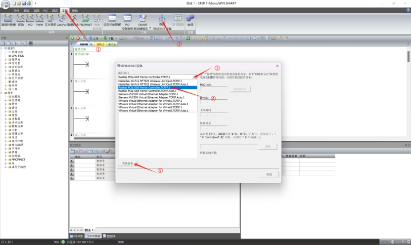
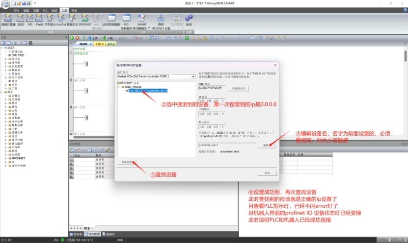
Perform a Profinet device scan within the LAN.
Assign a name to the Profinet slave to establish a correct connection.
4.3.4 Online monitoring of address signals
This module is used to view robot slot data.
By checking the address table and PLC start address, the IP address 190 of slot 2 (2 bytes) represents the slave heartbeat and is used for demonstration in this guide.
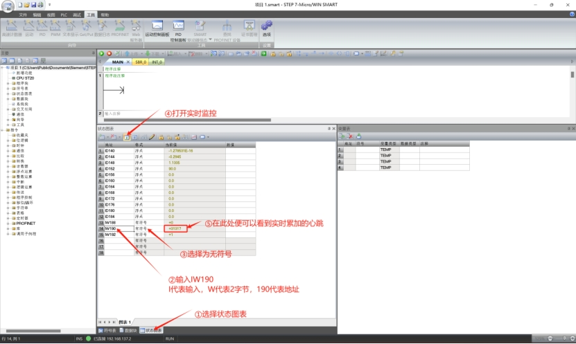
Note
- You can set other addresses by yourself to monitor changes in data.
- The ability to monitor signal changes indicates that the soft Profinet communication is normal and can be used normally.
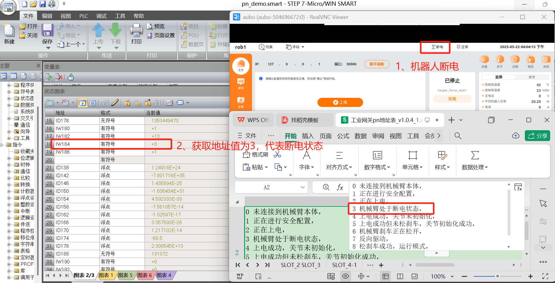
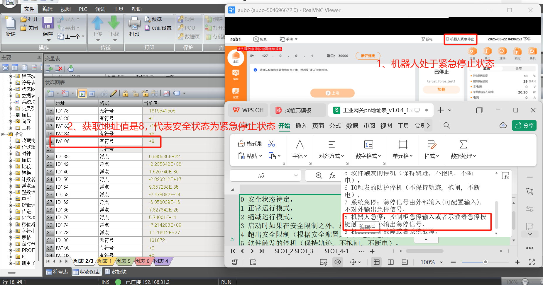
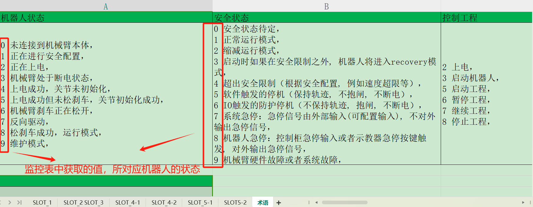
4.3.5 Reading robot status and safety status
By checking the address table and PLC start address:
- Slot 2, address 184 (2 bytes): Robot status
- Slot 2, address 186: Safety status
Query the robot arm’s current power-off and emergency stop status via these addresses.
4.3.6 PLC control of robot
From the address table and PLC start address, slot 6, address 200 (2 bytes) is defined as control engineering, which can be used to control robot actions such as start, pause, resume, stop, and power-on via the PLC. 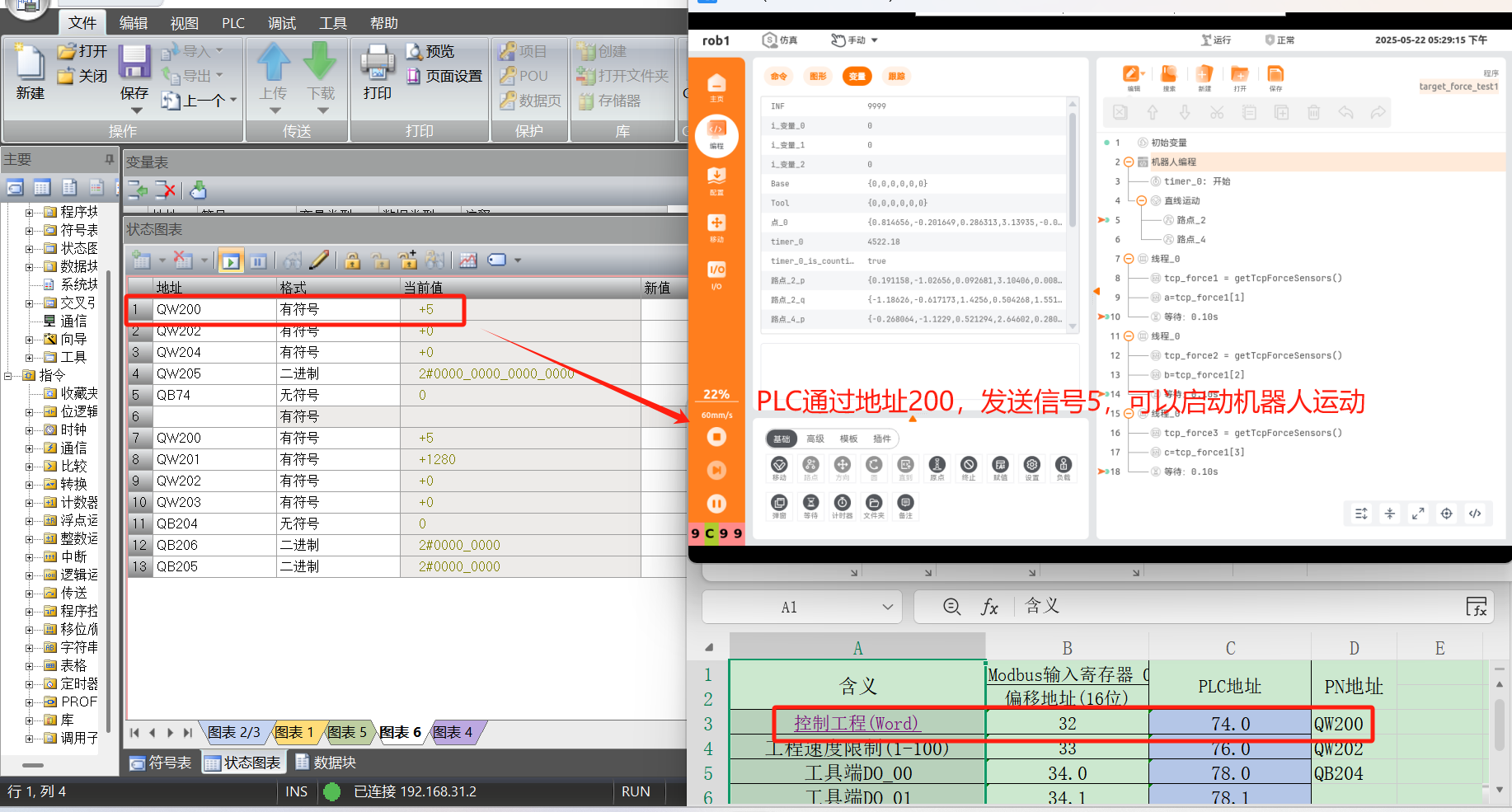
4.4 Profinet address table
4.4.1 How to display address table
Open the ARCS software homepage and click Configuration > Fieldbus > Profinet > View Address Table in the left navigation bar to view the address table details.
Note
- Wired teach pendant: Built into the ARCS software.
- Wireless teach pendant: Version 0.9.4-rc.14, paired with ARCS software v0.31.1-beta.38 or later.
- If the address table is not displayed in "Configuration > Fieldbus > Profinet", modify the configuration file /root/arcs_ws/config/aubo_scope.ini, configure the field under system: profinet_address_enabled=true, save it, and restart the ARCS software, then the address table will be displayed.
4.5 Chapter Summary
This chapter covers Profinet slave configuration and usage, including environment setup, testing, and address tables. After this chapter, you will be able to:
- Understand Profinet slave concepts and principles
- Master Profinet slave configuration steps
- Use a PLC to connect Profinet slaves and run communication tests
- View and use the Profinet address table
- Control basic robot movements via PLC
For configuration issues, see Chapter 7 for common problems and solutions.
5. ARCS Modbus User Guide
5.1 Quick Start Guide
Modbus includes Modbus masters and slaves. This chapter will help you quickly get started with Modbus configuration, providing comprehensive guidance from protocol introduction to practical applications.
5.2 Introduction to Modbus Protocol
- Modbus is a serial communication protocol, originally designed by Modicon (now Schneider Electric) in 1979 for PLC-based automation. It has become the de facto industrial communication standard, with two variants: Modbus RTU and Modbus TCP.
- Modbus RTU (Remote Terminal Unit): A binary protocol over serial lines (e.g., RS-485, RS-422, RS-232). Data is transmitted in binary form, with each byte re`presented by two hexadecimal characters. It is mainly used in industrial automation for long-distance communication.
- Modbus TCP (Transmission Control Protocol): An Ethernet-based protocol using TCP/IP for communication, leveraging existing Ethernet infrastructure. Compared to Modbus RTU, it supports more connections and offers faster speeds.
- Key differences between Modbus RTU and Modbus TCP:
Modbus RTU is based on serial communication methods, such as the RS-485 interface, and its transmission rate is limited by the performance of the serial interface.
Modbus TCP is based on the TCP/IP protocol stack, transmits data over the network, and supports a higher transmission rate.
5.3 Modbus Master Station
5.3.1 Introduction to the Master Station
In a Modbus network, the Master Station initiates communication, controlling and coordinating data exchange with Slave Stations. Acting as a commander, it actively requests data or sends commands to manage the network effectively.
5.3.2 Purpose of the Master Station
- In operations like welding, handling, and assembly, it acts as the Master Station, requesting data from or sending instructions to PLC Slave Stations based on task processes and status.
- Example: In auto parts assembly, robots may need to get position information from the PLC to grasp and install components accurately.
- Robot Master Stations often have a high degree of intelligence and can analyze and process the acquired data to make reasonable decisions.
- Example: Based on the equipment status information on the production line provided by the PLC, the robot can adjust its own working rhythm and movement sequence to achieve collaborative work with other equipment.
5.3.3 Modbus Entry
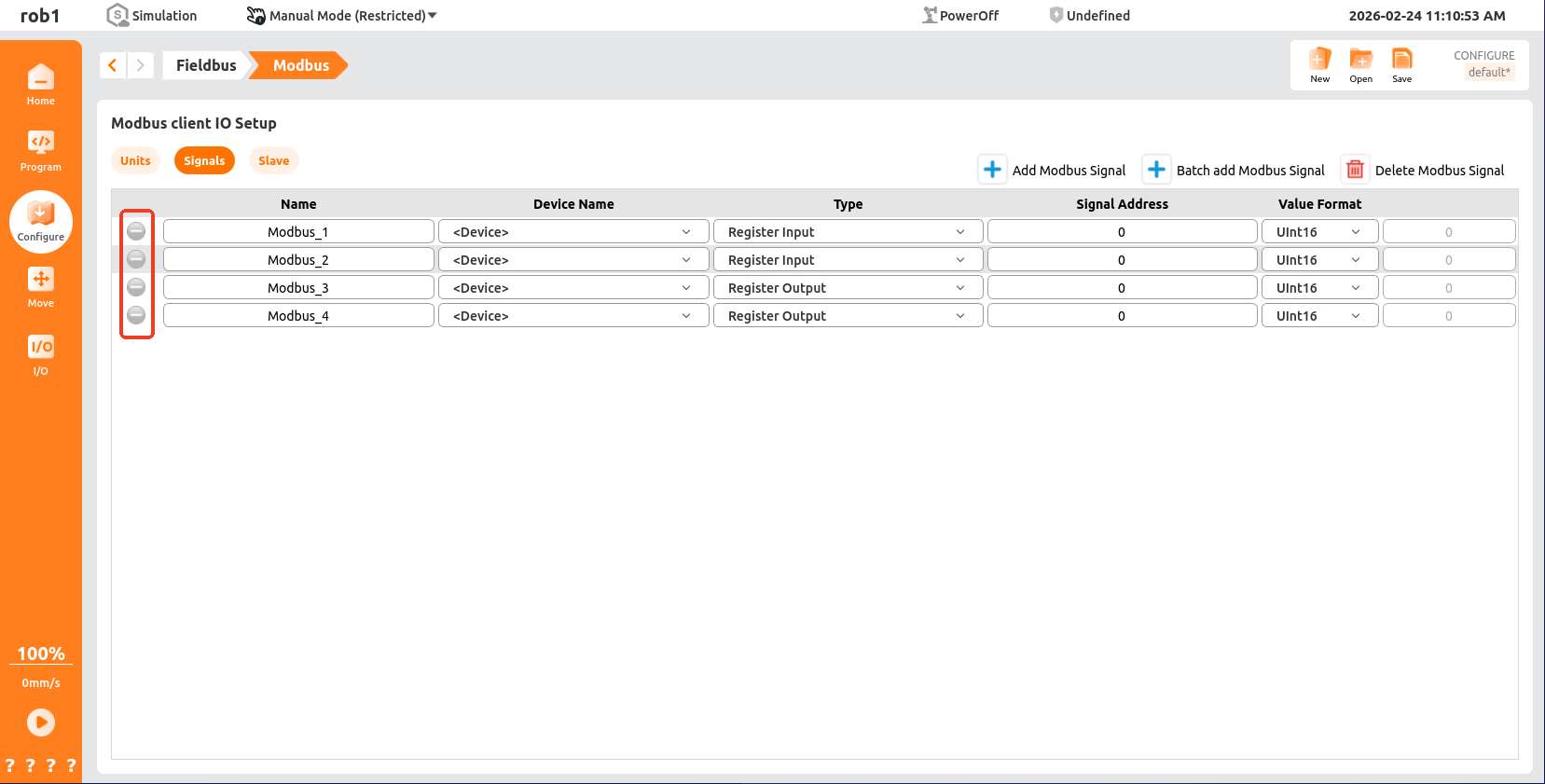
Open the ARCS software homepage, click "Configuration > Fieldbus > Modbus" in the left navigation bar to enter the [Modbus Client IO Settings] page. 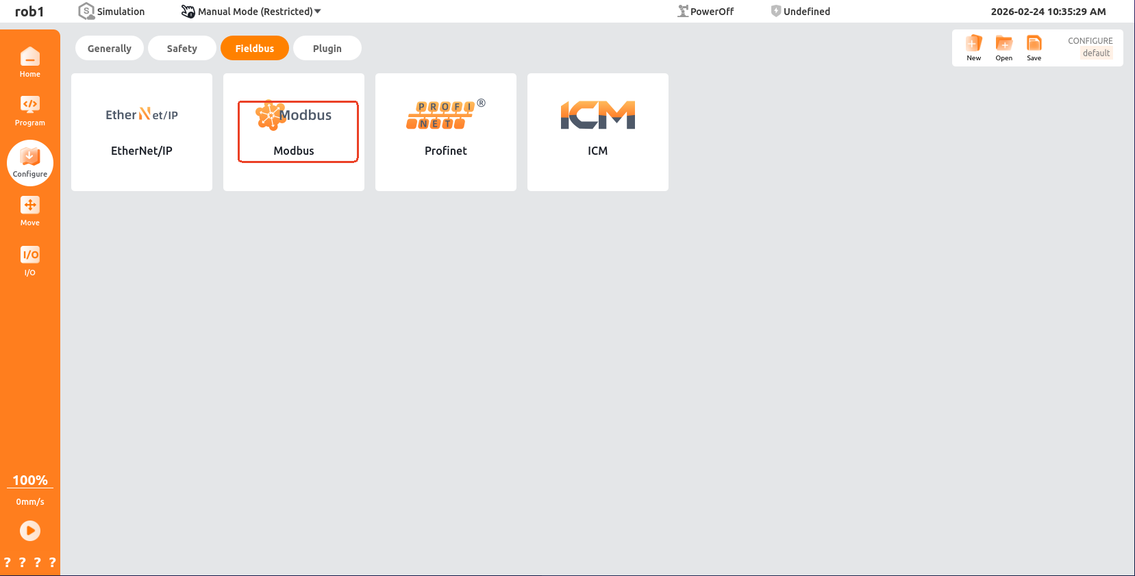
5.3.4 Master Station Modbus TCP
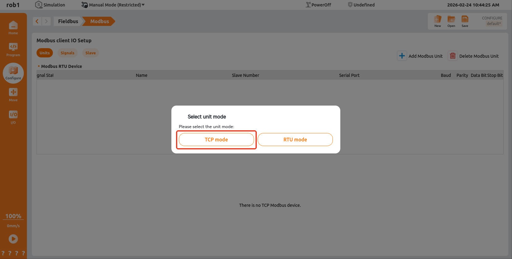
Unit Page: On the [Modbus Client IO Settings] page, click "Unit > Add Modbus Unit > TCP Mode".
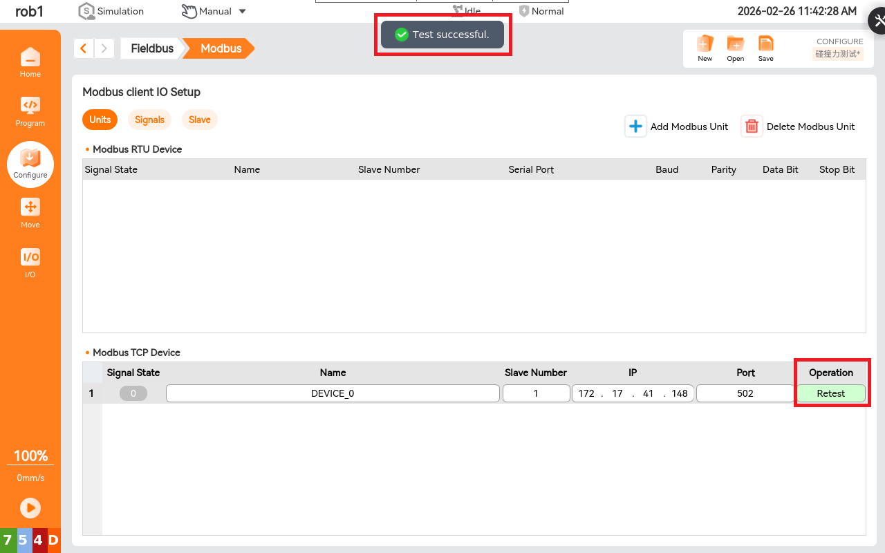
Modbus TCP device: Uses a TCP/IP connection and does not require checksum calculation. You can configure "Device", "Name", "Slave Number", "IP Address", "Port", and "Operation". After configuring the IP address, click [Test]. A "Test Successful" message indicates communication with the target device is possible. If not, check if they are on the same network segment and if the firewall is disabled, etc.
Warning
Ensure your TCP device and target device are on the same network segment.
Signal Page: On the [Modbus Client IO Settings] page, click "Signal > Add Modbus Signal".
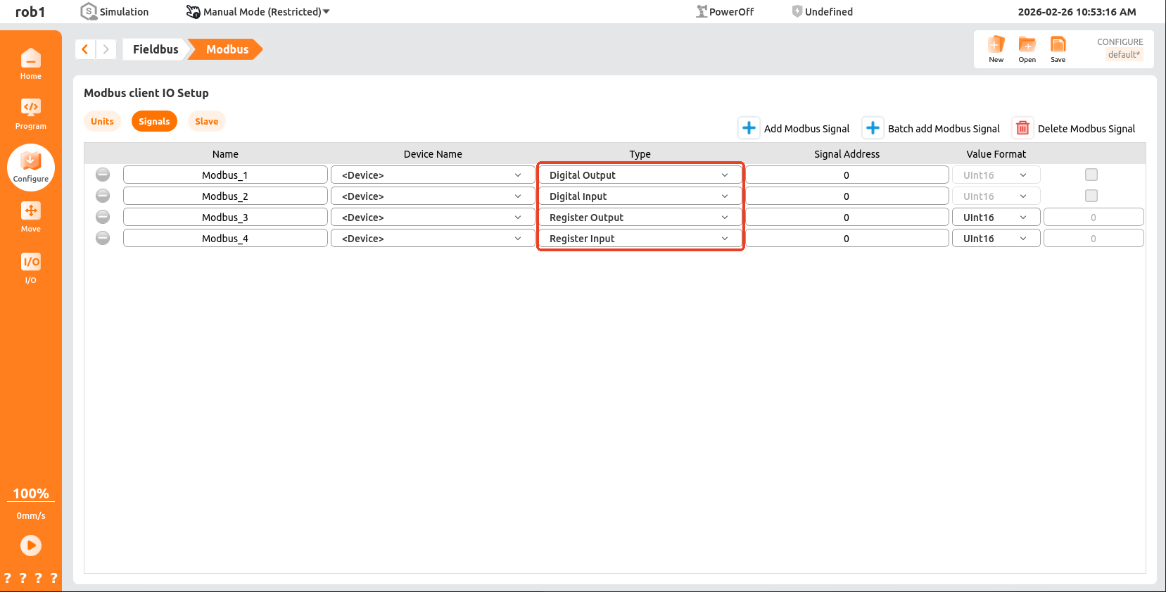
- COIL STATUS: Used to read and control the switch status of remote devices, and is usually used to control switching devices such as relays.
- INPUT STATUS: Used to read the input status of remote devices, and is usually used to read the status of input devices such as sensors.
- HOLDING REGISTER: Used for storing and reading data from remote devices, typically for storing control parameters, device status, and other information.
- INPUT REGISTER: Used to store input data from remote devices, typically used for storing data from input devices such as sensors.
- Green indicates normal communication, while gray and red indicate no communication. The red response codes are as follows:
- E1 : Illegal function (0x01): The function code received in the query is not an operation allowed by the server (or from the server).
- E2 : Illegal data address (0x02). The function code received in the query is not an operation allowed by the server (or slave). Please check the settings of the remote MODBUS server corresponding to the input signal address.
- E3 : Illegal data value (0x03) The value contained in the data field is not allowed for the server (or slave server). Please check whether the signal value is valid for the specified address on the remote MODBUS server.
- E4 : Slave Device Failure (0x04) When the server (or slave server) attempts to perform the requested operation, an unrecoverable error occurs. Please check if the device and wiring are damaged, and try restarting the device.
- E5 : A dedicated function where the response (0x05) is used in conjunction with programming commands sent to the remote MODBUS unit.
- E6 : The slave device busy (0x06) is used together with the programming commands sent to the remote MODBUS unit. It indicates that the device (server) cannot respond at present. Please wait or try to reconnect, and check whether the robot's IP address is the same as the IP addresses of other devices in the same local area network, which may cause a conflict.
5.3.5 Master Station Modbus RTU
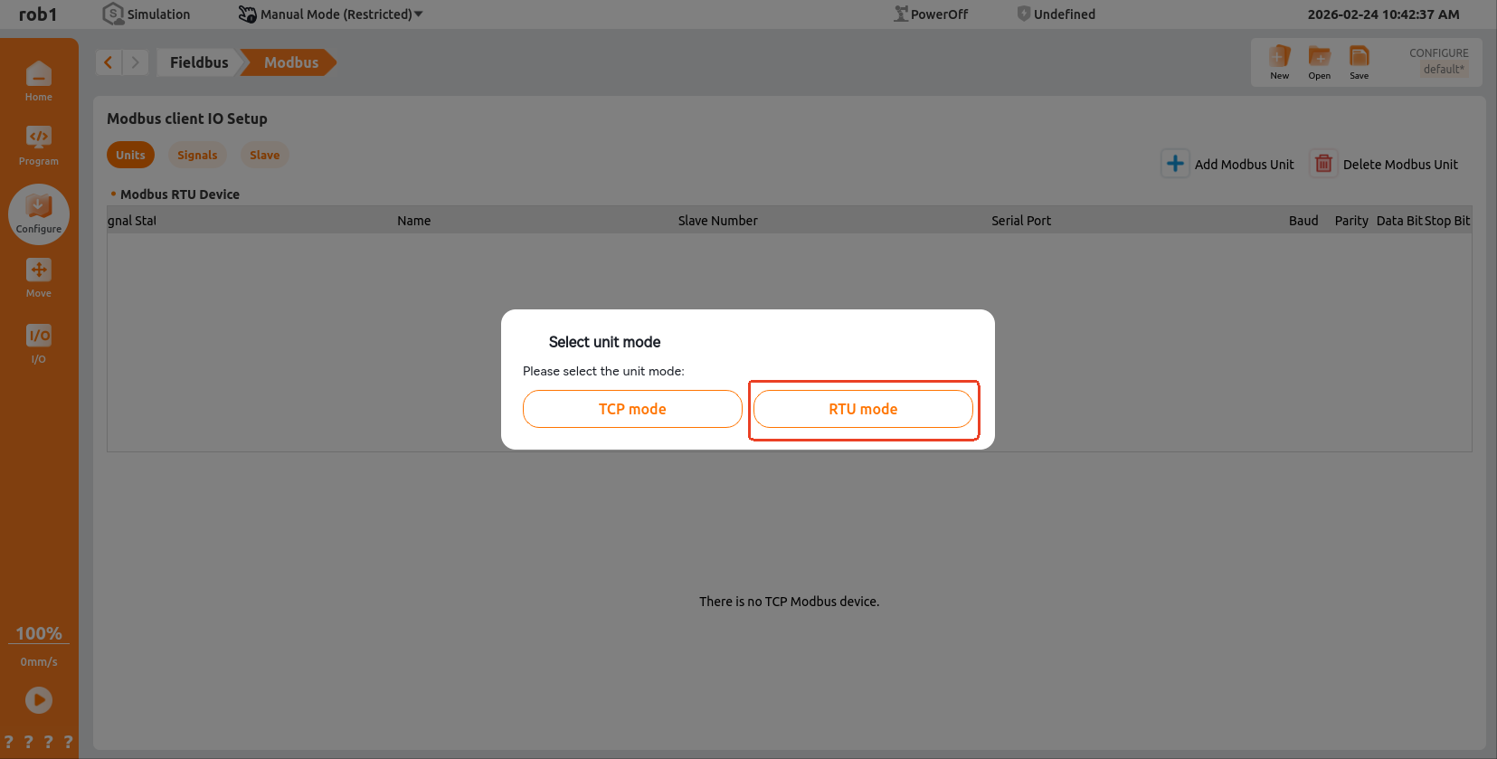
Unit Page: On the [Modbus Client IO Settings] page, click "Unit > Add Modbus Unit > RTU Mode".
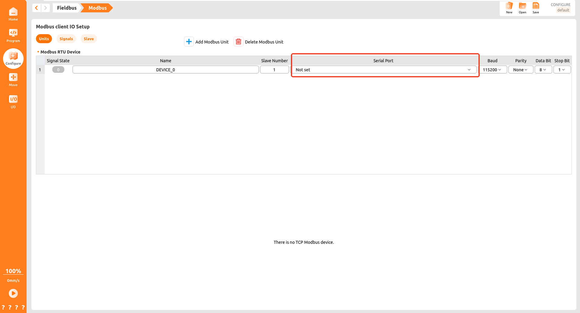
Modbus RTU Devices: The device "name", "slave number", "serial port number", "baud rate", "parity", "data bits" and "stop bits" can be configured.
Note
Modbus RTU devices use serial communication, so their transmission rate is limited by the RS-485 serial interface. If communication is unstable or the signal status flickers, reduce the baud rate. If there is no communication, verify the selected serial port and use a Modbus serial port assistant for troubleshooting.
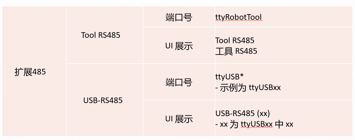
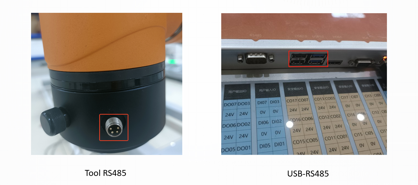
Modbus RTU communication relies on RS-485 serial communication at the end of the control cabinet or robotic arm. For the selection of Modbus serial ports, the following can be referred to:
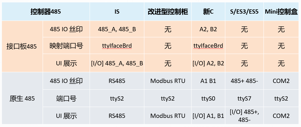
Control the RS-485 serial port number. The controlled RS-485 includes the terminal RS485 and USB485.
5.3.6 Modbus signals are used as IO in the configuration
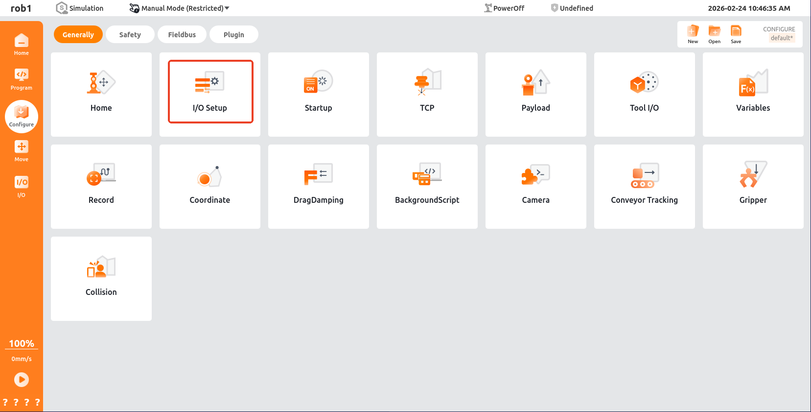
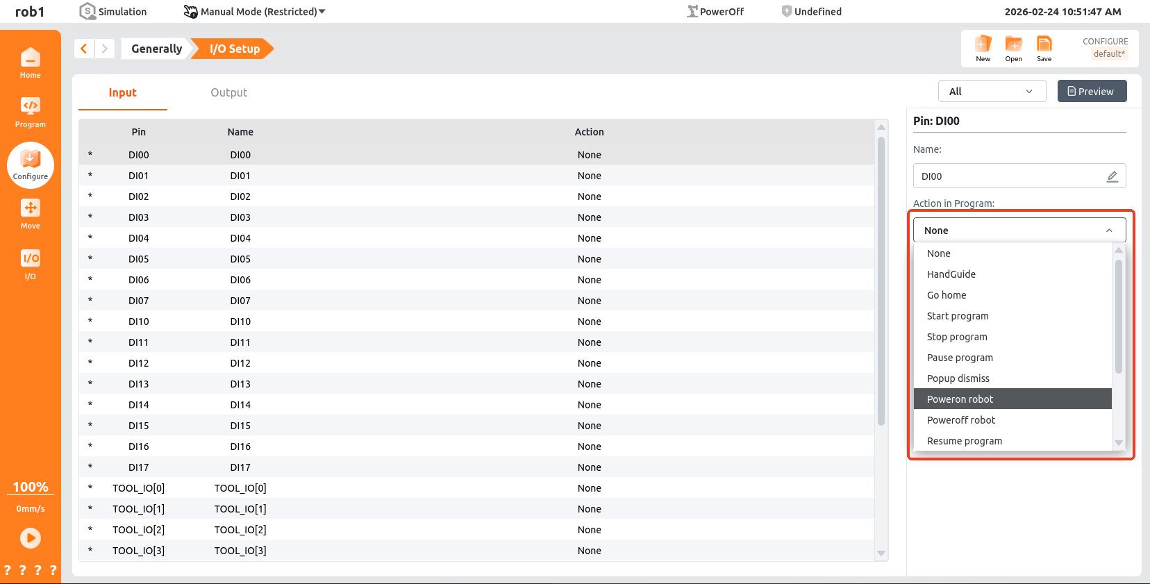
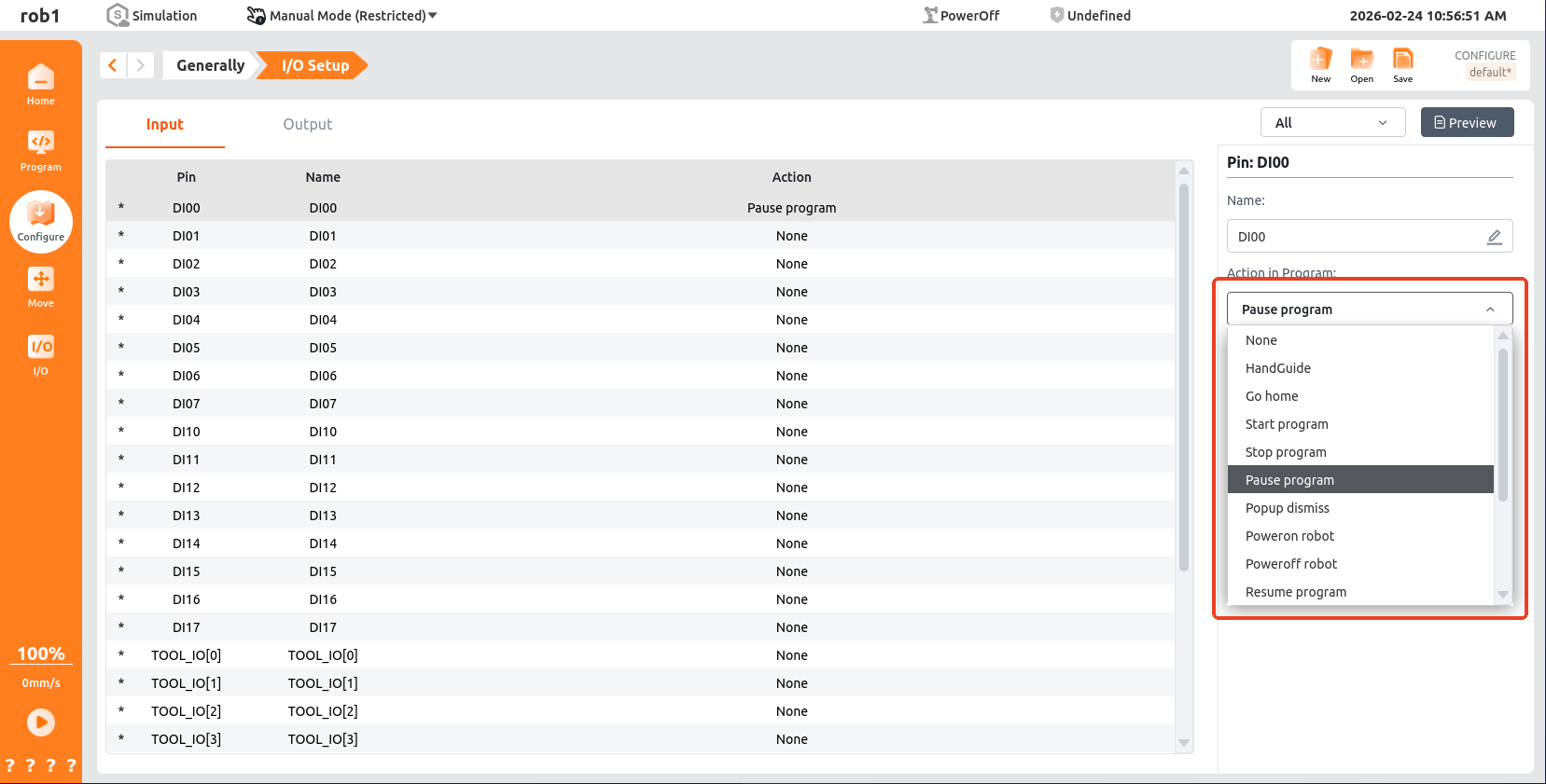
In the [Configuration] interface, click General > I/O Settings to configure I/O input actions. Except for drag teaching, other signals must be triggered in linkage mode (or take effect in manual/auto mode via OEM customization).
Note
Before this configuration, add Modbus signals of type "Register Input" or "Digital Input" in [Configuration > Fieldbus > Modbus > Signals].
Configure input actions for the corresponding Modbus signals.
Configure output actions for the corresponding Modbus signals.
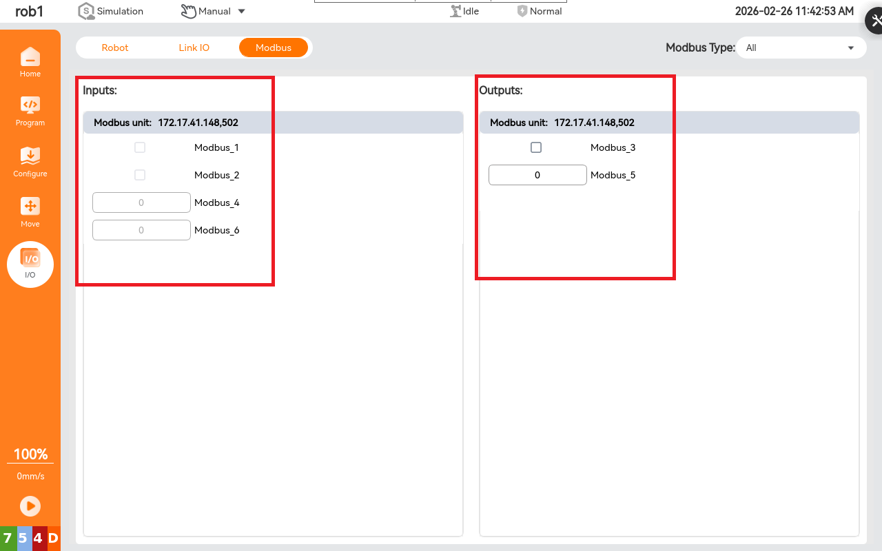
Users can click "IO > Modbus" in the left navigation bar to view changes in signal registers and digital signals.
5.3.7 Modbus signals are used in the program
- Setting nodes: Set the "digital output" and "register output" of Modbus signals, as well as the single pulse parameters of digital signals.
Note
It is usually used with "waiting for a signal" to verify that the signal is set successfully before executing subsequent processes.
- Waiting Node: The program continues only when the Modbus signal is satisfied; often used with the set signal.
- Assignment node: Assign a Modbus signal value to a variable for subsequent calls.
- If the node: Use the Modbus signal as a judgment condition; the program enters judgment when the signal is met.
- Loop Node: Use the Modbus signal as a loop trigger; the program enters the loop when the signal is met.
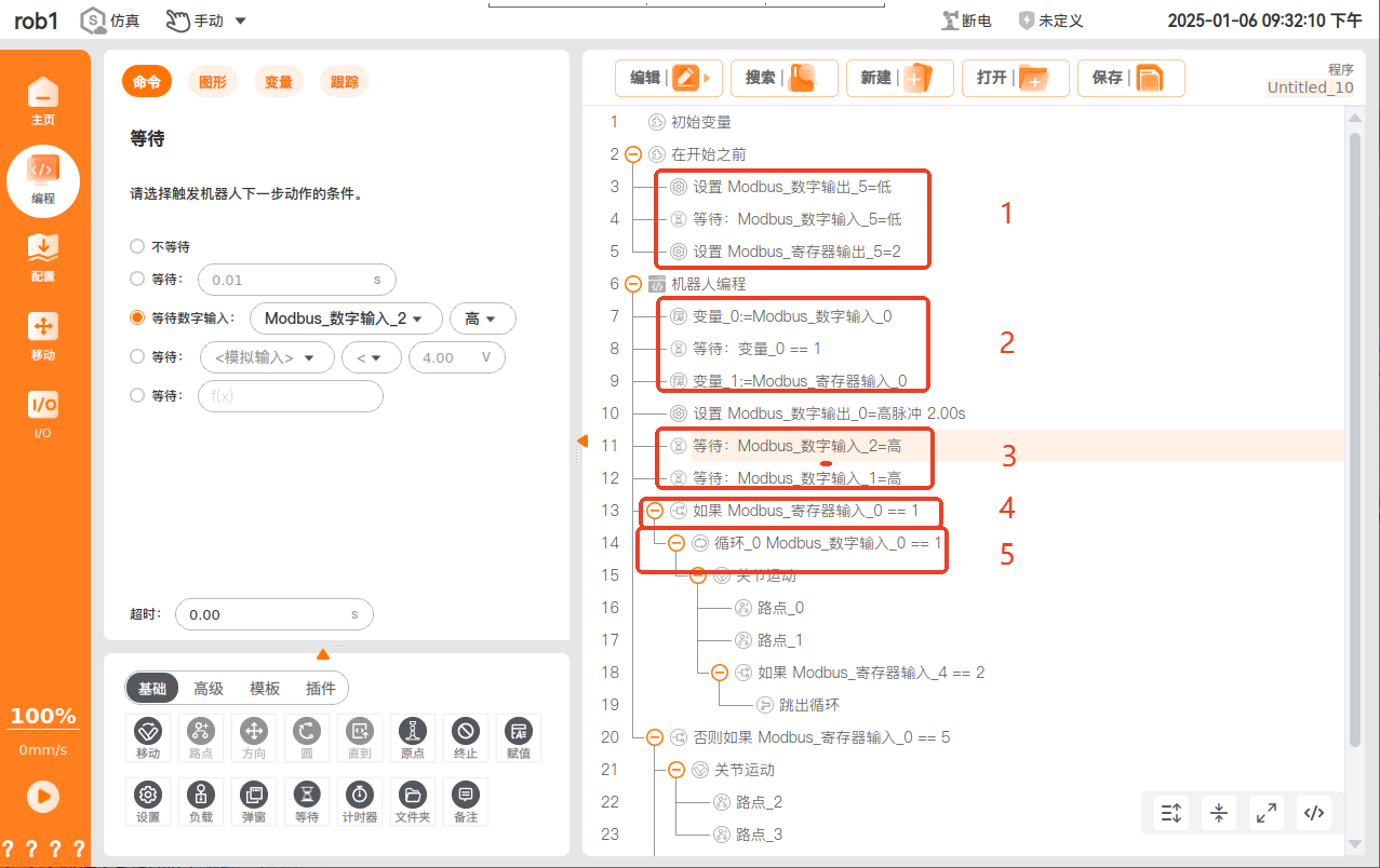
- Users can click "IO > Modbus" in the left navigation bar to view changes in signal registers and digital signals.
5.4 Modbus Slave Station
5.4.1 Introduction to the Slave Station
A Modbus slave responds to requests from the master and executes corresponding operations. In practice, it connects and controls production line devices, enabling information exchange and control command transmission between devices.
5.4.2 Purpose of ARCS Slave Station
Respond to the request from the Master Station and send the status information of the robotic arm to the Master Station in real time.
Respond to the request from the Master and send the controller's information to the Master.
Used as data during testing and debugging:
- Transmit the changes in the I/O signals of the robotic arm to the Master Station in real time.
- Transmit the custom signals from the Master Station to the robotic arm in real time.
Note:
When connecting a Slave Station through the Master Station of ARCS, there may be signal delays. This method should only be used during debugging and is not recommended for use in programs. If you need to read from or write to the registers of the Slave Station in the program, you can refer to Modbus User Guide - 3.6: Application Examples of General Register Read-Write Interfaces.
5.4.3 Slave address table update position
The Modbus slave address table is updated in "DingTalk Disk - Team Files > ARCS > External Folder > Modbus Slaves". If you are a customer, you can contact the technical staff of our company's Technical Service Department to obtain it. If you are a technical service staff, you can obtain it by yourself.
- Download address:modbus Slave Station Address Table_v1.14.xlsx
- Correspondence between Modbus slave version and ARCS version:
| Modbus version | ARCS version | Modification Date | Revised content |
|---|---|---|---|
| 1.0.4 | 0.29.2-beta.10 | 2024-8-19 | 1. Add control engineering. 2. Add the project operation status. |
| 1.0.7 | 0.31.0-beta.3 0.32.0-alpha.23 | 2024-12-26 | Update the robot series and robot sub-models. |
| 1.0.8 | 0.29.4-rc.6 0.31.0-beta.5 0.32.0-alpha.32 | 2025-1-9 | Add Modbus slave output operation mode and heartbeat. |
| 1.0.9 | 0.29.5-rc.10 0.31.0-rc.12 0.32.0-alpha.73 | 2025-3-4 | Increase the percentage of the running speed of the read-write project. |
| 1.0.11 | 0.29.5-rc.21 0.31.0-rc.26 0.31.1-beta.7 0.32.0-alpha.117 | 2025-4-25 | Add Modbus slave to release the protective stop. |
| 1.0.12 | 0.29.5-rc.22 0.29.6-rc.1 0.31.0-rc.28 0.32.0-alpha.136 | 2025-5-12 | Add a Modbus slave error clearing pop-up window, including releasing the protective stop and resetting the interface board. |
| 1.0.13 | 0.31.1-beta.9 0.32.0-alpha.131 | 2025-5-15 | Add the bool register. |
| 1.14 | 0.31.1-beta.10 0.32.0-alpha.139 | 2025-5-21 | Add switching projects. |
| 1.14 | 0.31.1-beta.10 0.32.0-alpha.140 | 2025-5-22 | 1. Add operation mode to support output linkage mode. 2. Add output of Modbus version number. |
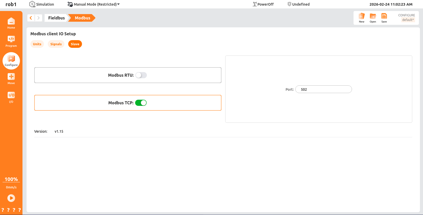
5.4.4 Slave Modbus TCP
On the [Modbus Client IO Settings] page, click [Slave] and turn on the "Modbus TCP" switch.
Note
After starting the Slave Station, it can be connected via Master Station devices such as PLC or modscan. For the Slave Station address, please refer to the definition in the Modbus slave protocol.
5.4.5 Slave Modbus RTU
On the [Modbus Client IO Settings] page, click [Slave] and turn on the "Modbus RTU" switch.
Note:
- The Modbus RTU slave can only be started after the serial port parameters have been configured.
- Once enabled, the serial port parameters cannot be modified and must be modified after being disabled.

Modbus RTU communication relies on RS-485 serial communication with the control cabinet or the end of the robotic arm. The serial port parameters of different devices are as follows:
Note:
Modbus RTU devices are based on serial communication, and their transmission rate is limited by the performance of the RS-485 serial interface. If the communication is unstable and the signal status flickers, the baud rate value can be reduced. If there is no communication, check whether the selected serial port is appropriate, and the Modbus serial port assistant can be used for troubleshooting.
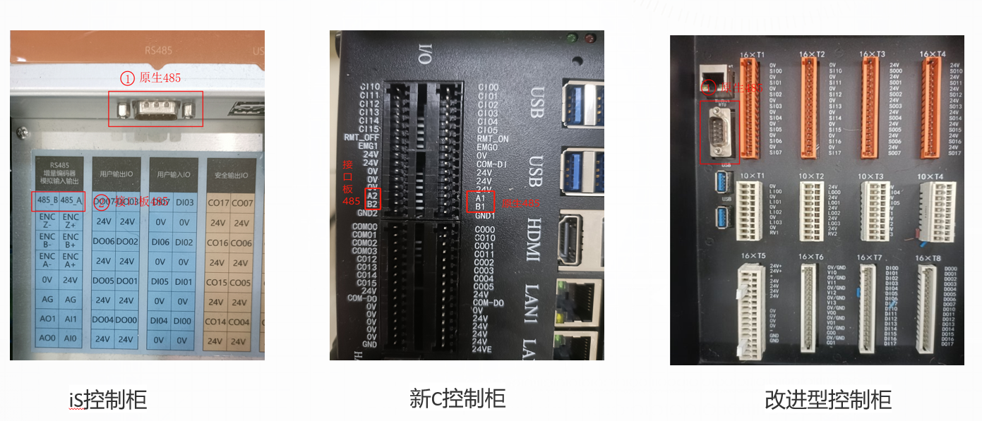
Control the RS-485 serial port number; the controlled RS-485 includes the terminal RS485 and USB485.
5.5 Interface Application
5.5.1 Description and Notes for the modbusSendCustomCommand Interface Function
- Send the command specified by the user to the Modbus unit at the specified IP address.
- Since no response will be received, it cannot be used to request data, and the function code for reading data is temporarily unavailable.
- The user is responsible for providing meaningful data for the provided function codes.
- The built-in functions are responsible for constructing Modbus frames, so users do not need to worry about the length of the command or input data in CRC format.
5.5.2 Parameter definition and format
// 接口定义
int modbusSendCustomCommand(const std::string &device_info,int slave_number, int function_code, const std::vector<uint8_t> &data);

// device_info: Device information
     * The device information is in RTU format.
     * For example:"serial_port,baud,parity,data_bit,stop_bit"
     * (1)serial_port The parameter specifies the name of the serial port.
     * For example,On Linux, it is "/dev/ttyS0" or "/dev/ttyUSB0".
     * (2)The baud parameter specifies the baud rate for communication, such as 9600, 19200, 57600, 115200, etc.
     * (3)The parity parameter specifies the parity check mode, where N represents no parity, E represents even parity, and O represents odd parity.
     * (4)The data_bit parameter specifies the number of data bits, and the allowed values are 5, 6, 7, and 8.
     * (5)The stop_bit parameter specifies the number of stop bits, and the allowed values are 1 and 2.
     *
     * The device information is in TCP format, for example: "ip address,port"
     * (1) The ip address parameter specifies the IP address of the server
     * (2) The port parameter specifies the port number on which the server listens.

// slave_number: Specifies the slave number used for custom commands

// function_code: Specify the function code of the custom command
     * MODBUS_FC_READ_COILS                0x01   // Read coil register
     * MODBUS_FC_READ_DISCRETE_INPUTS      0x02   // Read discrete input status
     * MODBUS_FC_READ_HOLDING_REGISTERS    0x03   // Read holding registers
     * MODBUS_FC_READ_INPUT_REGISTERS      0x04   // Read input register
     * MODBUS_FC_WRITE_SINGLE_COIL         0x05   // Write a single coil
     * MODBUS_FC_WRITE_SINGLE_REGISTER     0x06   // Write a single register
     * MODBUS_FC_READ_EXCEPTION_STATUS     0x07   // Read abnormal status (serial line only)
     * MODBUS_FC_WRITE_MULTIPLE_COILS      0x0F   // Write multiple coils
     * MODBUS_FC_WRITE_MULTIPLE_REGISTERS  0x10   // Write multiple registers
     * MODBUS_FC_REPORT_SLAVE_ID           0x11   // Report the slave ID (limited to serial lines)
     * MODBUS_FC_MASK_WRITE_REGISTER       0x16   // Write to the register with blocked words
     * MODBUS_FC_WRITE_AND_READ_REGISTERS  0x17   // Read & write registers

// data: must be a valid byte value (0-255)
     * { 0x00, 0x02, 0x00, 0x0F }
     * { 0x06, 0x0A, 0x0F, 0x08, 0x00, 0x0F }
5.5.3 Example of invocation
// Define IP
#define MODBUS_IP          "172.16.3.111,502"
// Create an object
RpcClientPtr impl;
// Send custom data
impl->getRegisterControl()->modbusSendCustomCommand(MODBUS_IP, 1, 0x06, { 0x00, 0x02, 0x00, 0x0F });
6. Guide to Using Soft EIP
6.1 Quick Start Guide
The EIP Slave Station is a soft protocol stack EIP. This chapter will help you quickly get started with EIP configuration, providing you with comprehensive configuration guidance from protocol introduction to practical applications.
6.2 Introduction to the EIP Protocol
6.2.1 Definition of the Agreement and Its Core Advantages
EIP (Ethernet/IP) is an industrial Ethernet protocol based on the TCP/IP protocol stack. It is developed by ODVA (Open DeviceNet Vendors Association) and widely used for real-time data exchange between industrial automation devices. Its core advantages include:
- Strong compatibility: Supports linkage with various industrial devices such as PLCs, robotic arms, and sensors, and is compatible with equipment from mainstream manufacturers (including Inovance, Omron, Siemens, etc.).
- High real-time performance: Adopts the "producer-consumer" communication model, enabling millisecond-level data transmission to meet real-time control requirements in industrial scenarios.
- Flexible configuration: Standardizes device descriptions through EDS (Electronic Data Sheet) files, simplifying the adaptation process between different devices.
6.2.2 Applicable scenarios
Soft EIP does not require additional hardware modules. It implements the EIP slave function through a software protocol stack and is suitable for communication scenarios between mainstream PLCs such as Inovance and Omron and AUBO robotic arms. Typical applications include:
- Automobile parts assembly: PLC controls the synchronization of the robotic arm's grasping position (reading the robotic arm's joint angles and position coordinates);
- Electronic device welding: Real-time transmission of robotic arm IO signals (digital output/input status) through EIP;
- Production line collaboration: PLC issues speed limit instructions, and the robotic arm feeds back operating status (safety status, voltage/current).
6.3 Application of Soft EIP in Inovance PLC
6.3.1 Preparation of the configuration environment
6.3.1.1 Preparation of software and hardware
Software preparation:
- ClickDownload Data Packet,Install Inovance PLC debugging software
AutoShop V4.10.0.0. - Please contact AUBO developers to download the EDS file:
compatible_eip_slave_v0.0.1.eds. - ARCS software versions:
0.29.3-rc.9and above,0.31.0-beta.1and above,0.32.0-alpha.9and above.
- ClickDownload Data Packet,Install Inovance PLC debugging software
Hardware preparation:
- Inovance
Easy 521robot arm body - laptop computer
- Network cable
- HUB or switch
- Inovance
Configuration file:
Modify the configuration file
aubo_control.confCheck the corresponding port and network card.
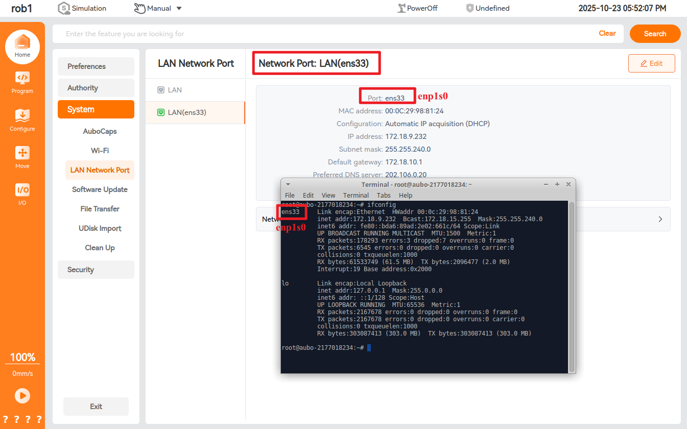
Modify the configuration file
aubo_control.conf,Add the following code:[[Extension]] location = "extensions/aubo_comm/aubo_comm.so" bundle = "aubo_comm" alias = "aubo_comm" enable = true [Extension.options] rpc_tcp_port = 30004 rpc_ws_port = 9012 rpc_http_port = 8484 rtde_tcp_port = 30010 rtde_ws_port = 9013 # EIP Function Configuration [eip] eip_enable = true eip_ifname = "enp1s0" # The network card name should be changed according to the actual situation. The physical network card actually used by the current system is enp1s0
6.3.1.2 Hardware wiring
Connect the PLC, control cabinet, and local computer to the same network via a switch.
6.3.1.3 Set a static IP for PLC
Open the
AutoShopsoftware, click "File > New Project" as shown in the figure below, follow the steps to mark the operation, fill in the project name, and select the Inovance PLC model Easy521.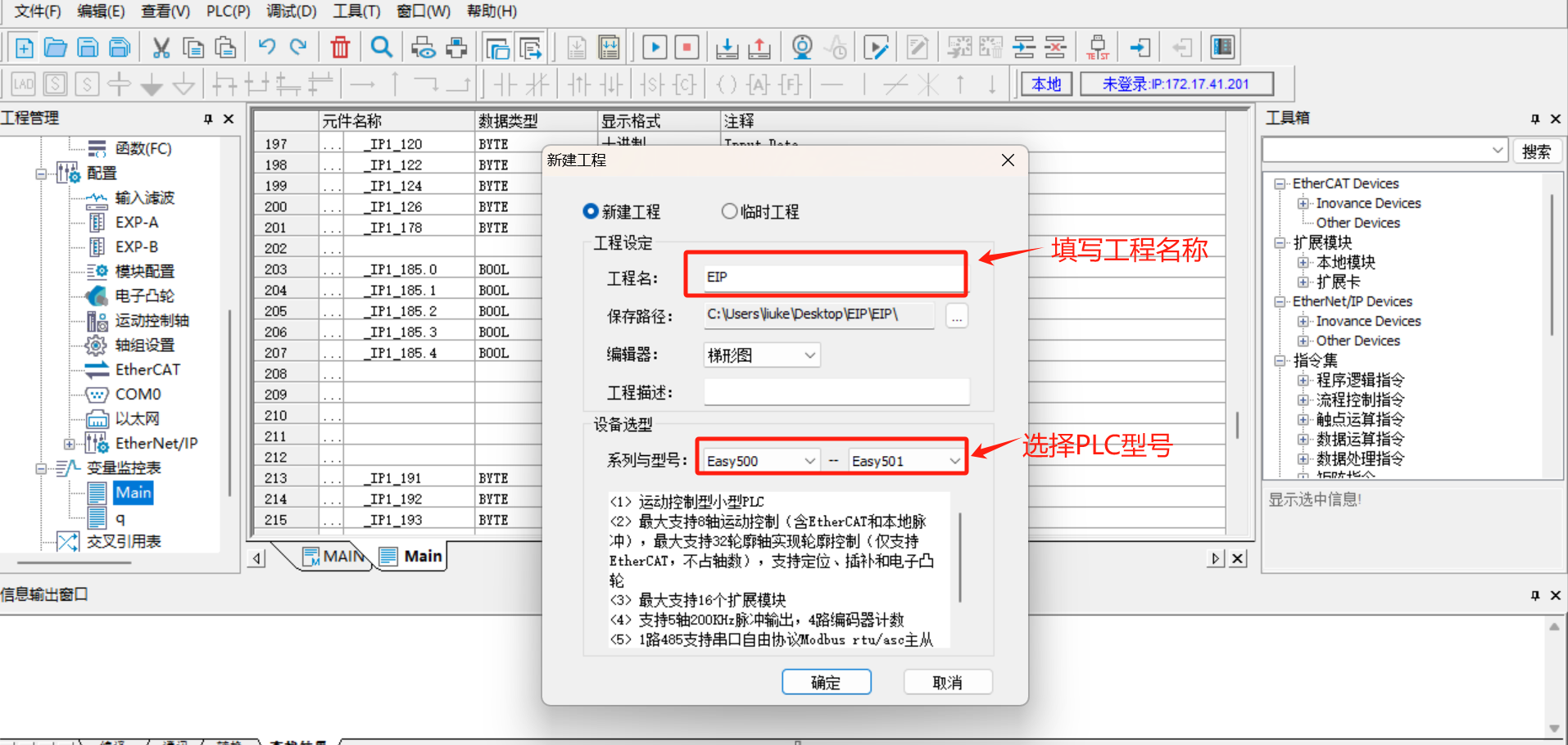
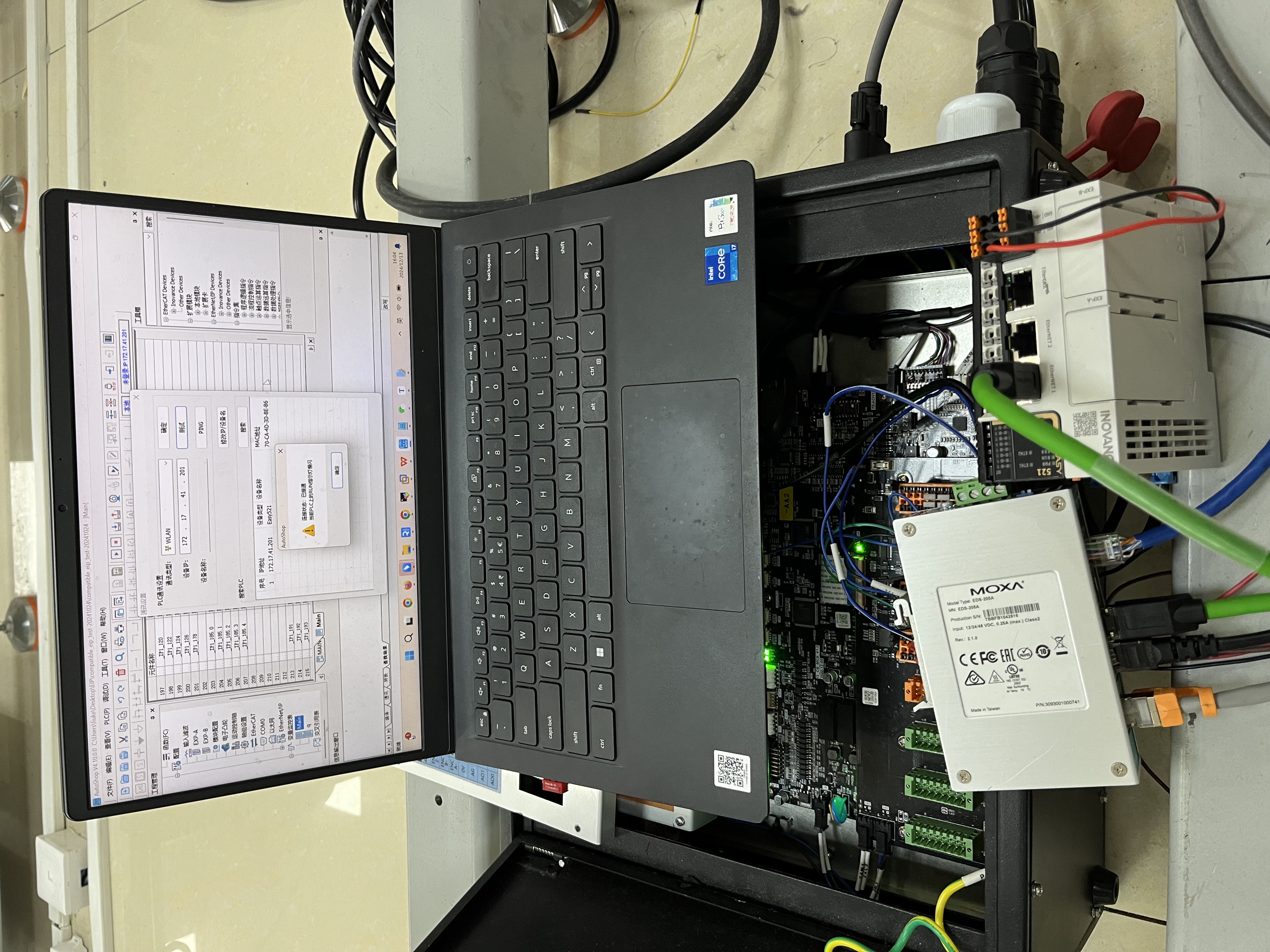
Click on the [Tools] in the menu bar, select [Communication Settings], choose the corresponding network port from the [Communication Type] drop-down box, click to search for PLCs, and after a successful connection, the communicating PLCs can be found.
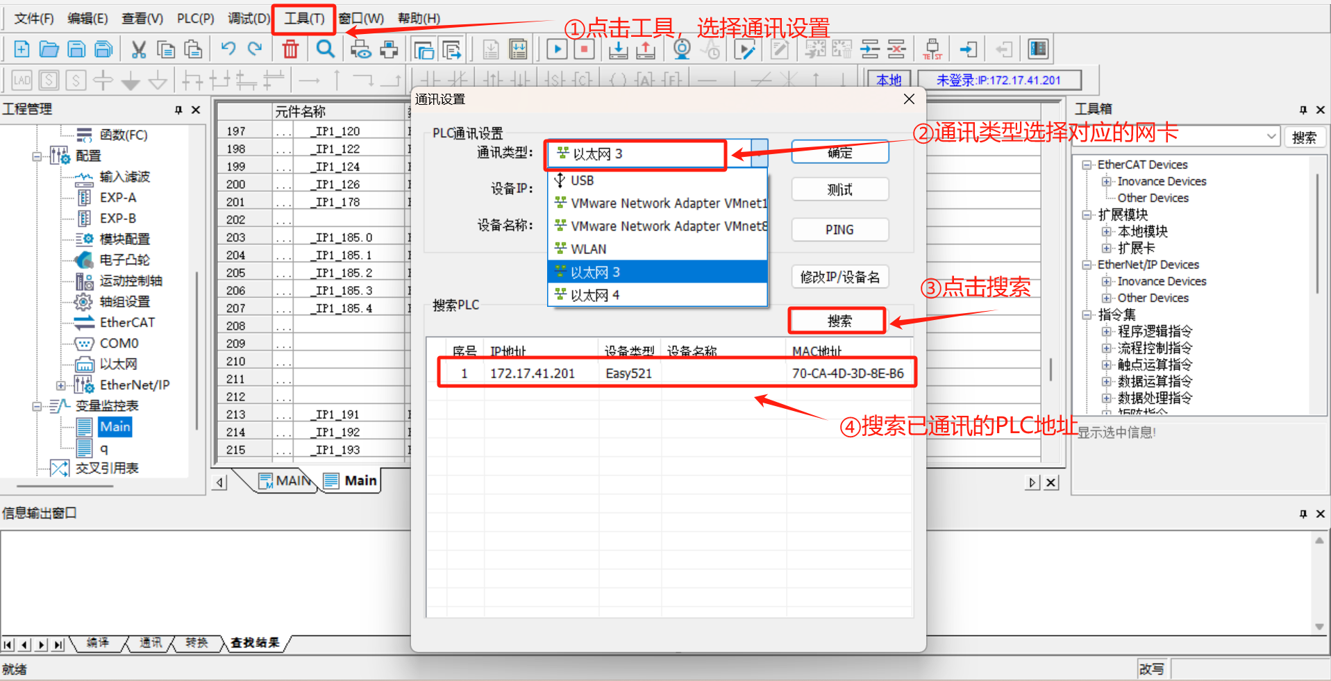
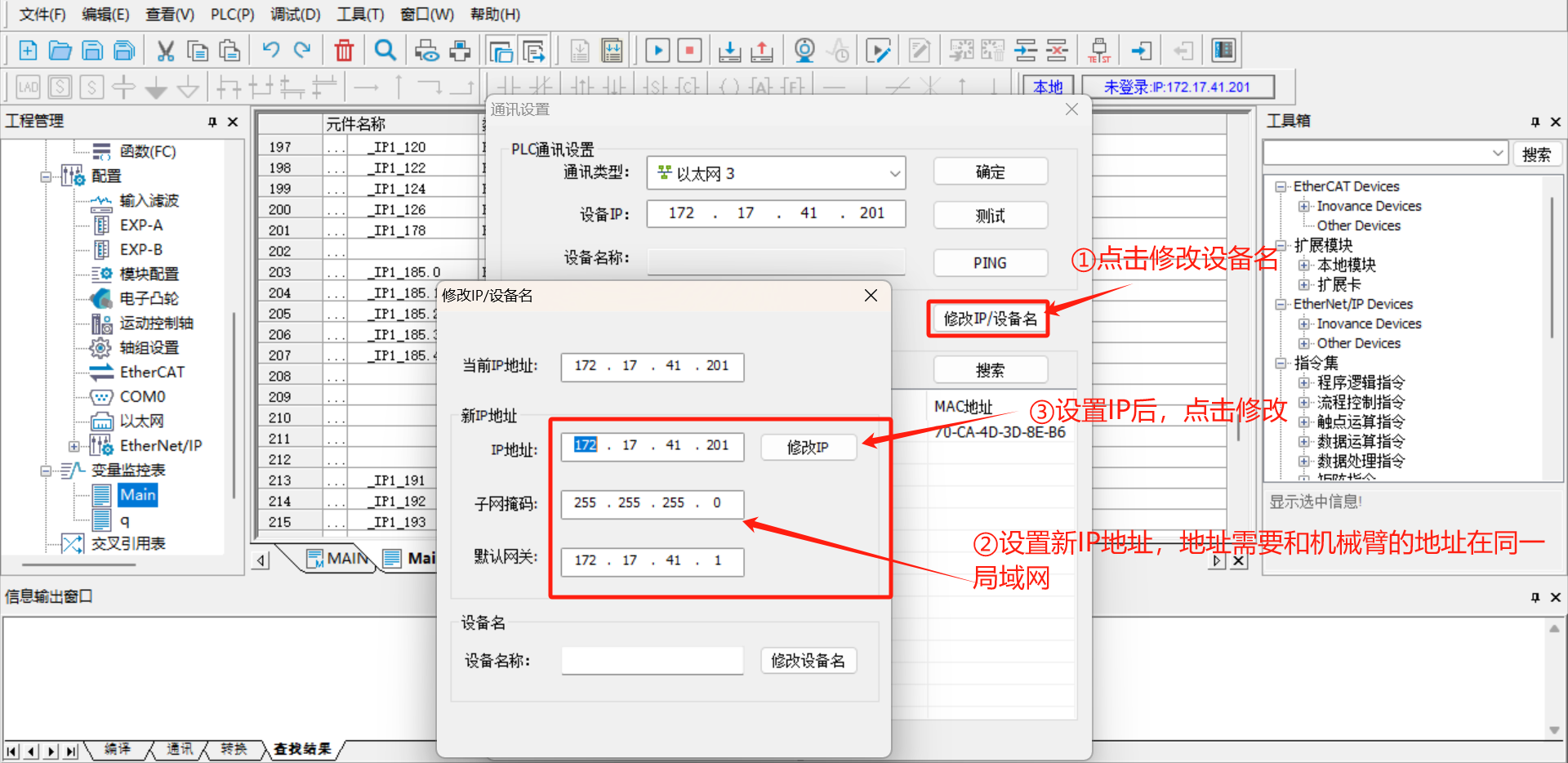
Click [Modify IP/Device Name], set a new IP address, which needs to be in the same network segment as the robotic arm and the laptop.
Note: If the PLC cannot be found through online search, you can use a
type-Cto USB cable to connect the PLC to the laptop, selectUSBas the communication type, and then you can modify the IP of the PLC device.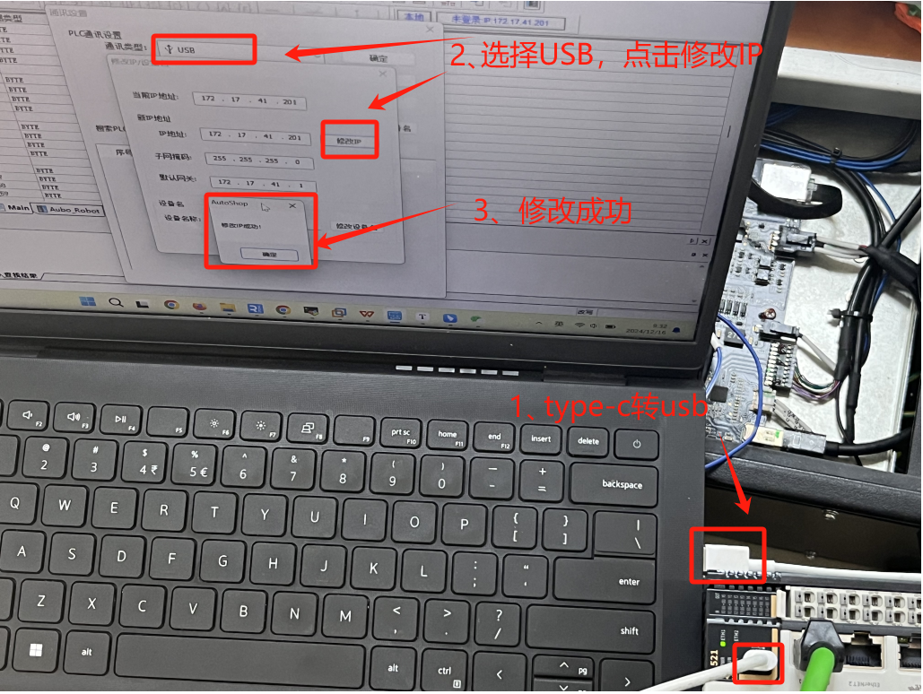
6.3.1.4 Setting a static IP for the robotic arm
Open the ARCS software homepage, click "Settings > System > Network > Static Address" in the left navigation bar to set a static IP. The static IP address must be in the same network segment as the PLC and the laptop. 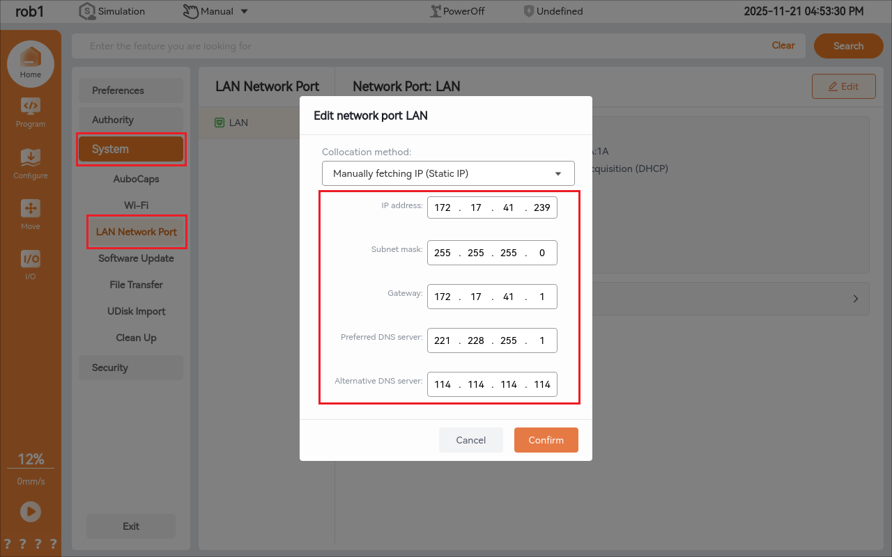
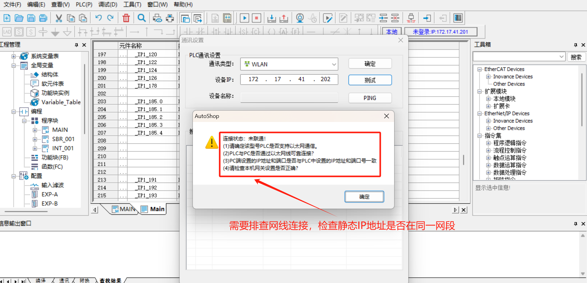
6.3.1.5 Communication test
Click [Test], and the link status in the figure shows as connected. At this point, the PLC and the laptop have established normal communication.

If the test connection status is not connected, it is necessary to check the network cable connection and verify whether the IP settings of the PLC are in the same network segment as the laptop.
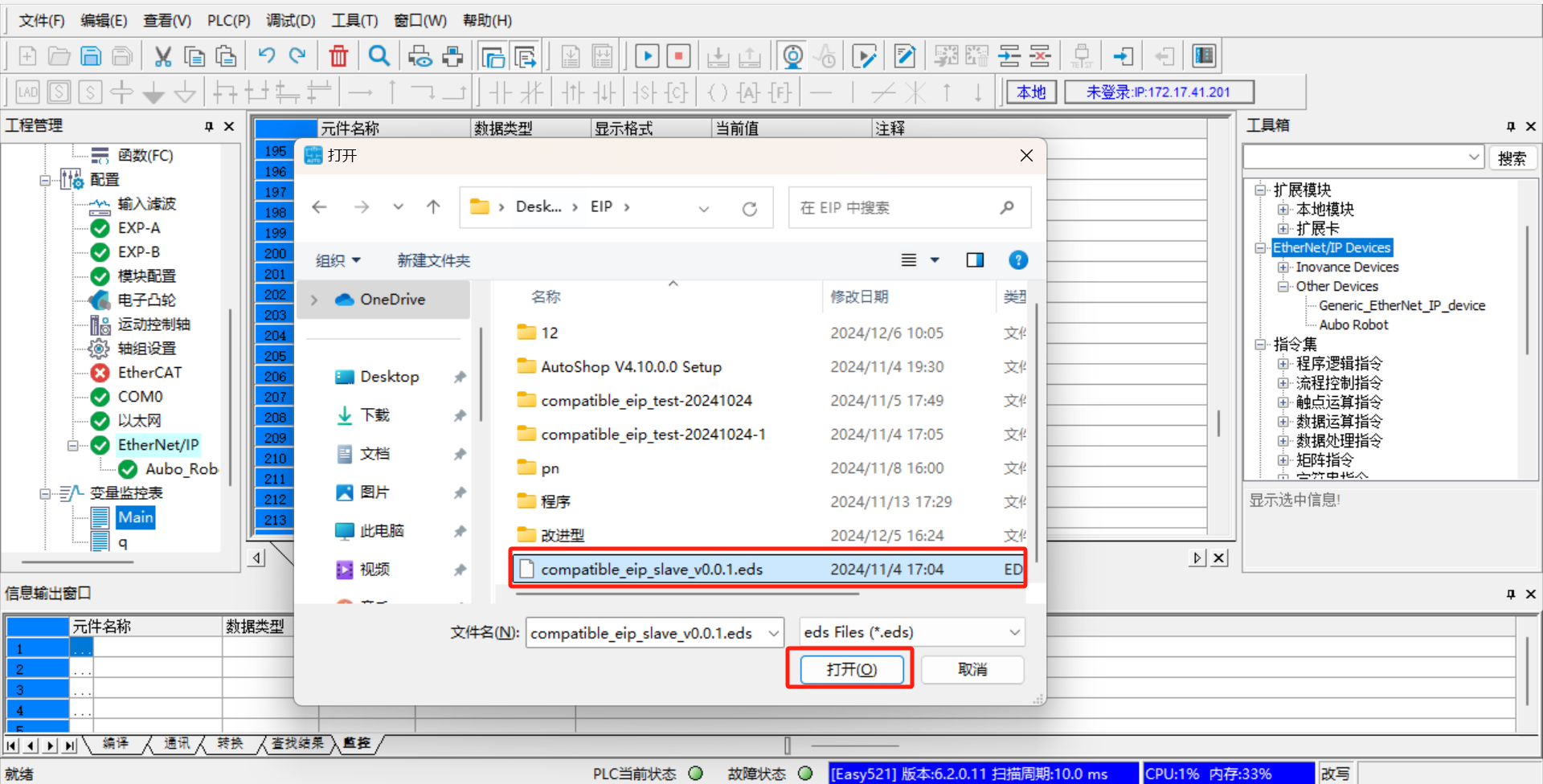
6.3.1.6 PLC import EDS file
Click "Engineering Management > Configuration > Ethernet/IP" on the left side of the software.
Click on "Toolbox > Ethernet/IP Device" in the right-side menu bar of the software, right-click on [Ethernet/IP Device], and [Import EDS] will appear. Click on [Import EDS] to import the pre-prepared EDS file, as shown in the following figure:
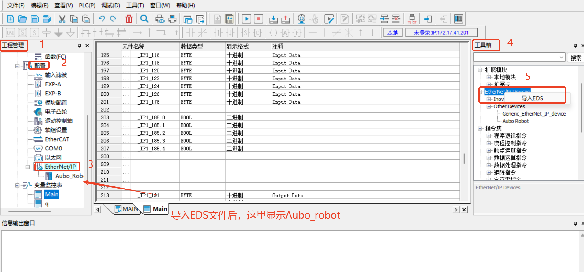
Note
The EDS file is provided by AUBO developers, and you can contact the relevant engineers to obtain the latest version.
6.3.1.6 Device Station IP Settings
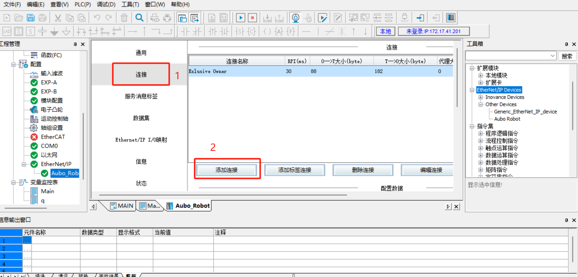
- Double-click [Aubo_Robot], set [IP Address] to the real IP of the robotic arm, select [Exact Match] in [Electronic Matching], and use the default values for other settings, as shown in the following figure:
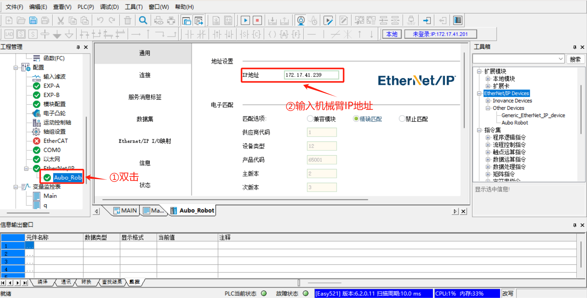
- Click [Connect] > [Add Connection].
6.3.1.7 Save and monitor the project
After all configurations are completed, save the project, then click [Download] > [Run] > [Monitor], following the steps shown in the figure below:
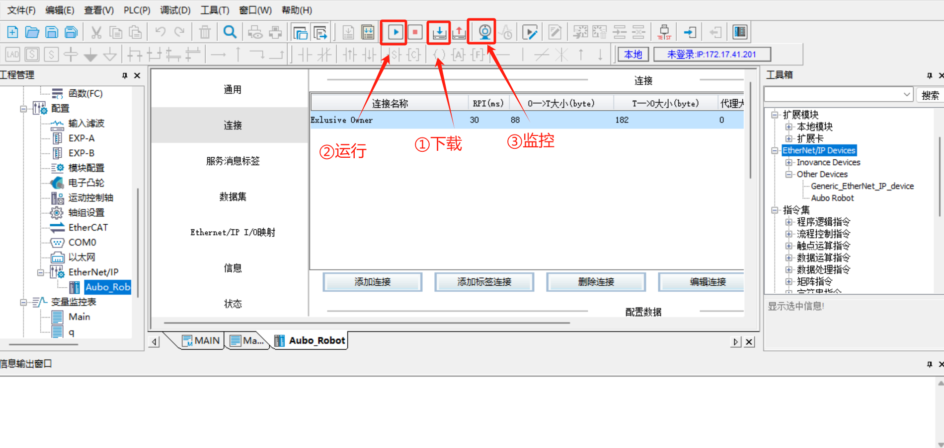
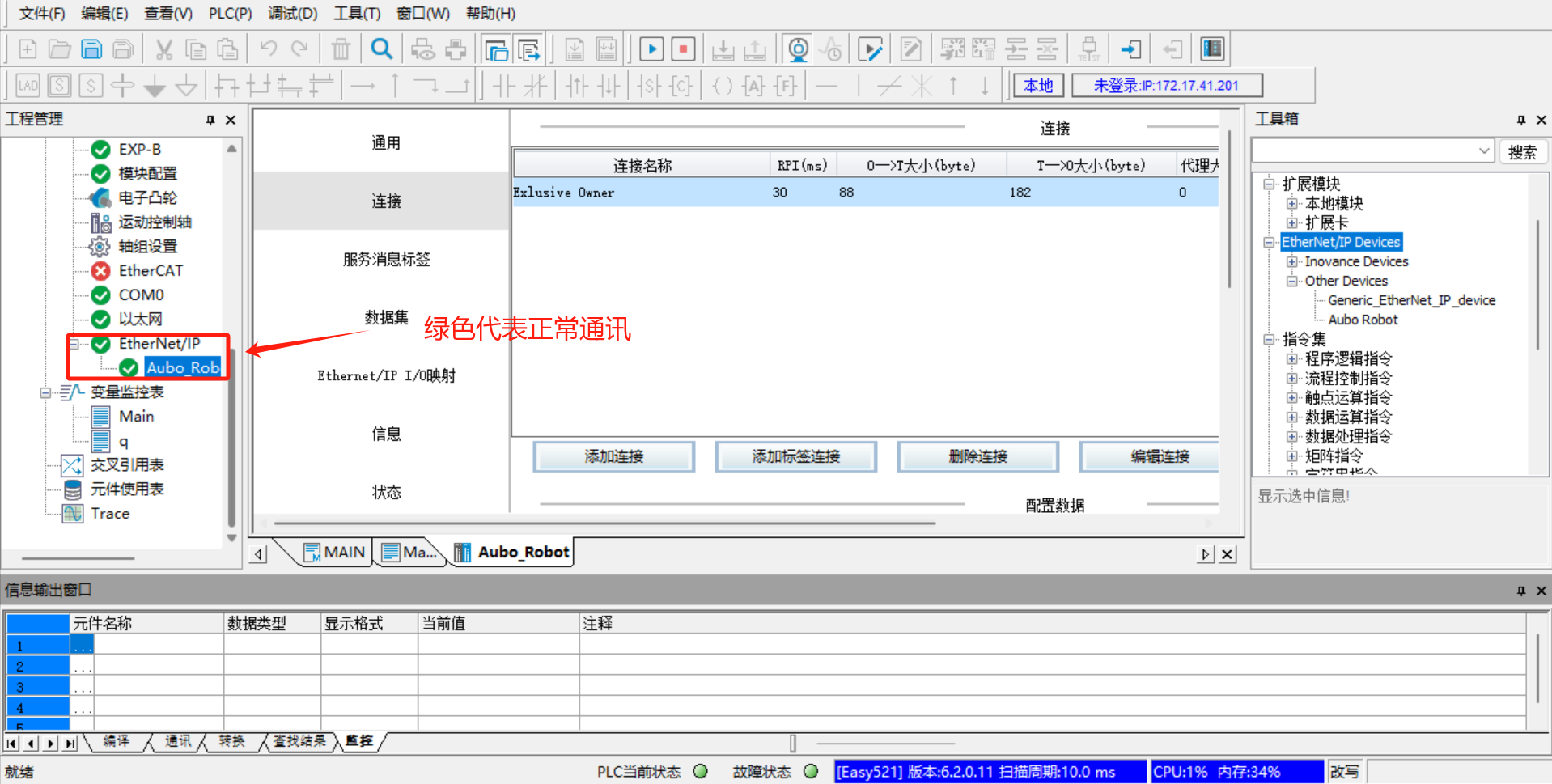
Switch the PLC to run mode. After clicking "Run > Monitor", go to "Configuration > Ethernet/IP" on the left side. Both [Ethernet/IP] and [Aubo_Robot] turn green, indicating that the PLC is successfully connected to the robotic arm and can communicate normally.
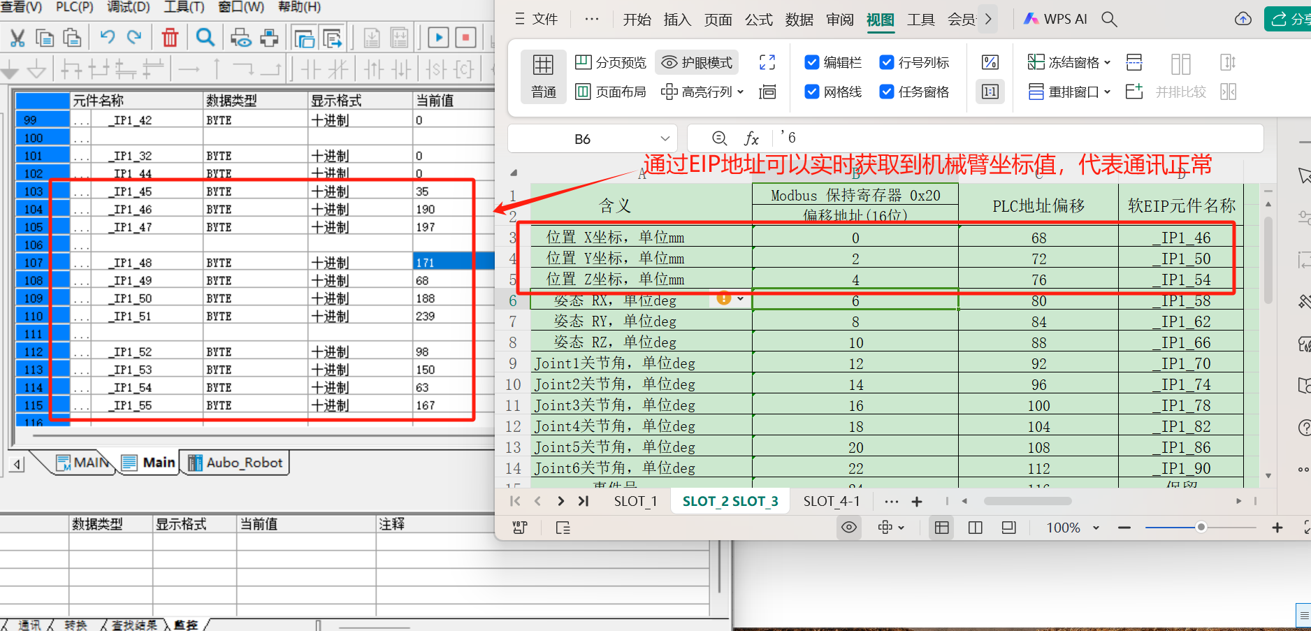
Add the address variable for monitoring. Click "Variable Monitoring Table > Main" on the left side. In the Main table, click [...] to pop up the variable selection dialog box [Variable Input Assistant], then click "UserVar > SYS_EIP" to select and assign an address.
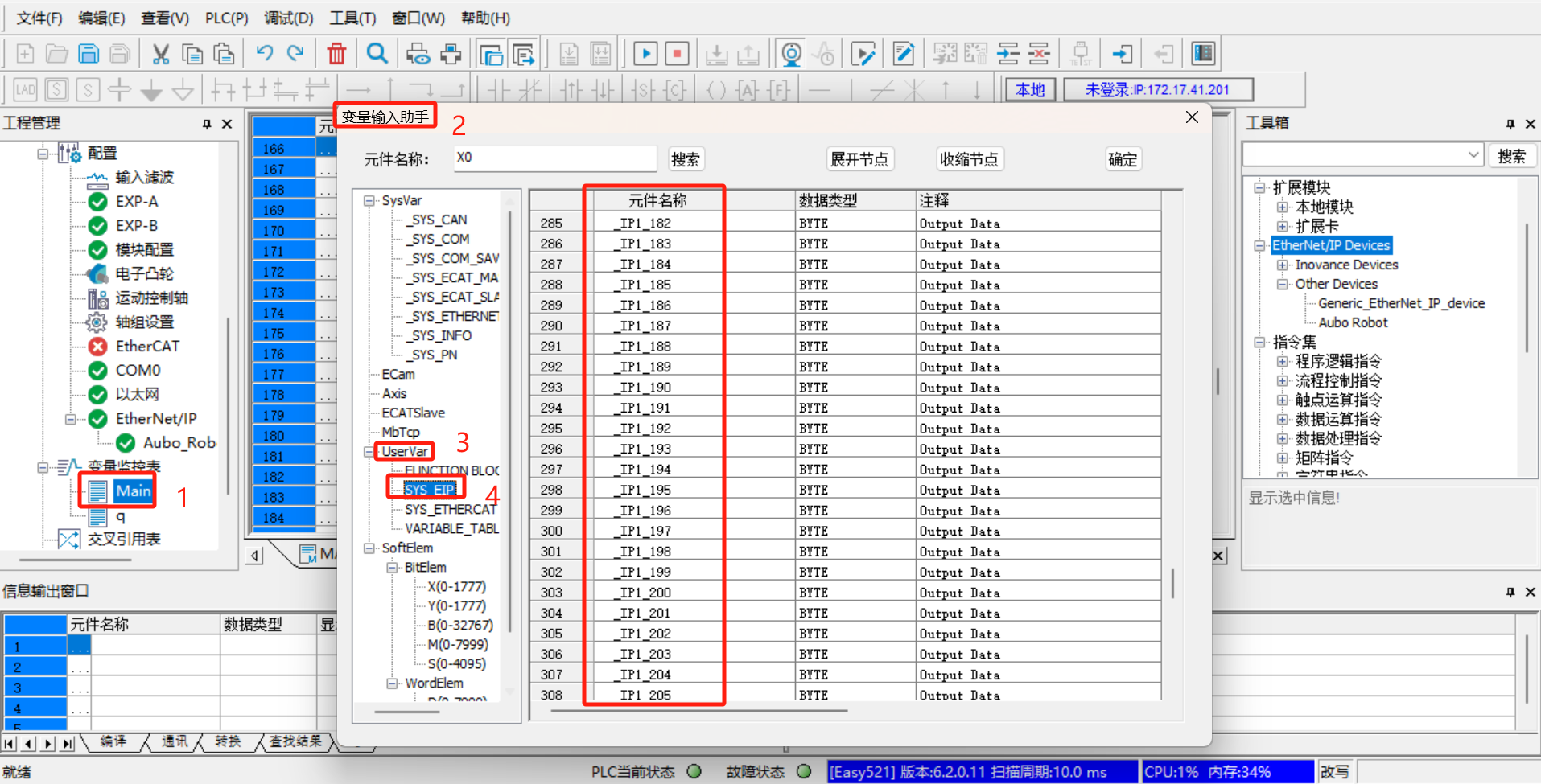
The address in
SYS_EIPis imported based on the EDS file. The address here is pre-allocated by developers according to the EIP address table. This address table corresponds to the EIP communication address table provided by developers, and the corresponding address field can be selected according to the EIP address table.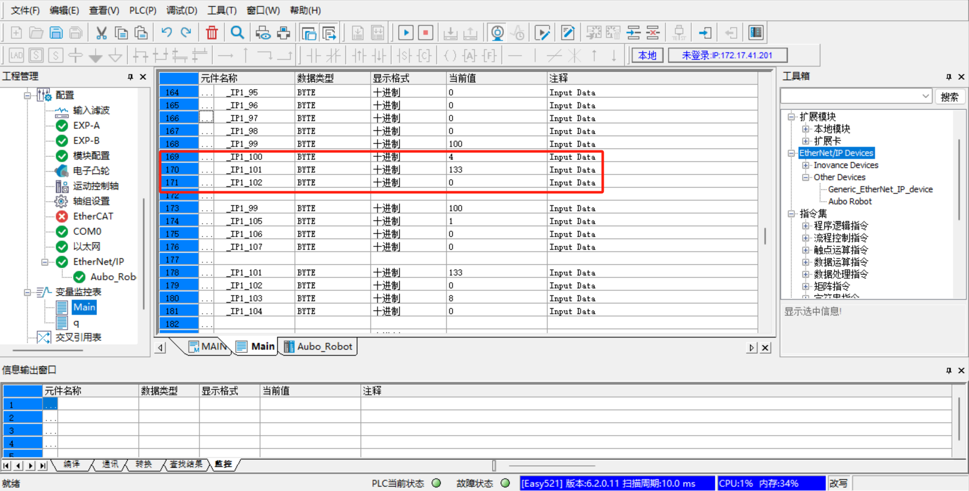
The following are some monitoring addresses added based on the EIP address table, including IO signals, position coordinates, joint angles, voltage, current, temperature, robot status, general coils (Robot => PLC), general registers (Robot => PLC), general coils (PLC => Robot), general registers (PLC => Robot), control engineering, etc.
6.3.1.8 Example of communication between PLC and controller
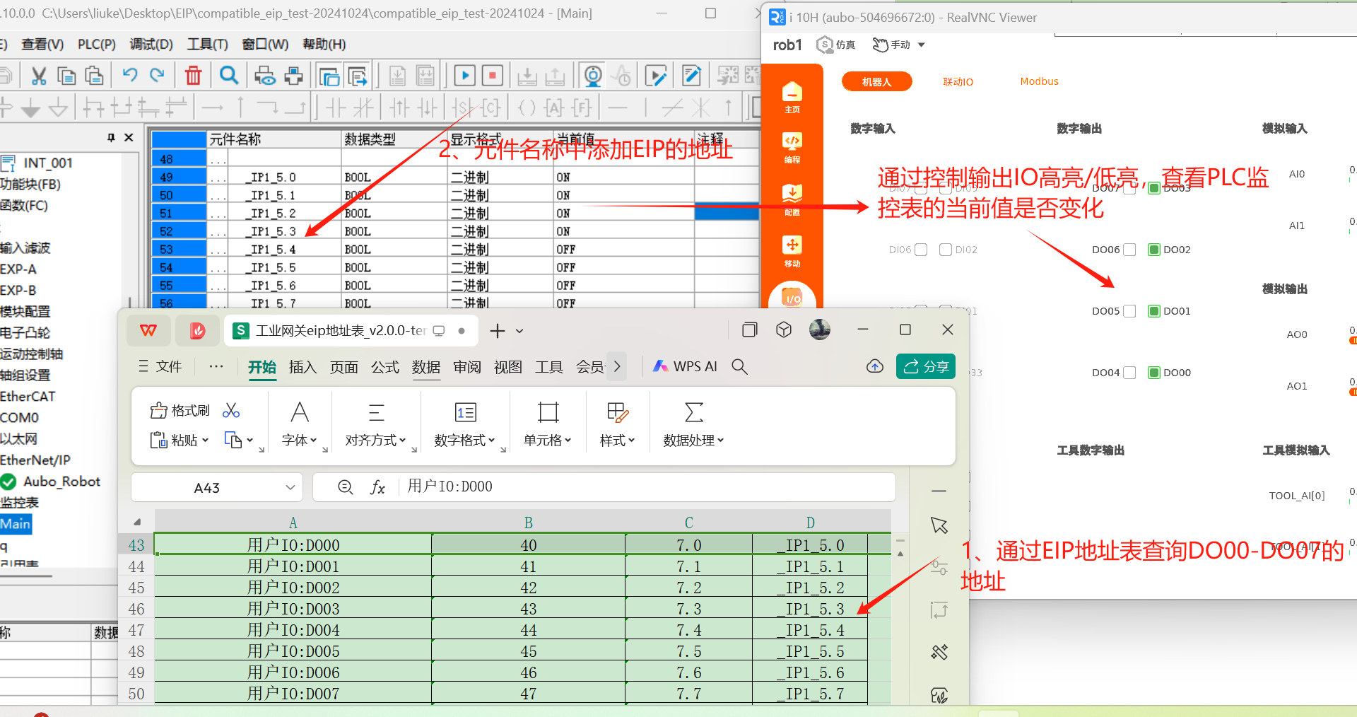
Slot 1 Digital Output Monitoring
Through the EIP address table query, the EIP addresses of DO00-DO07 are _IP1_5.0 to _IP1_5.7. Add monitoring addresses to the variable monitoring table. Open [arcs software] > [IO] > [Robot] > [Digital Output], highlight the signals DO01-DO07 through operation, and observe whether the values in the variable monitoring table change synchronously.
Card Slot 2 Robot Status Monitoring
Through EIP address table query, the EIP addresses for engineering speed limit, end speed, robot status, and safety status are
_IP1_99,_IP1_101,_IP1_103, and_IP1_105. By entering these addresses in the monitoring variable table, the obtained values can be observed to determine the status of the robot.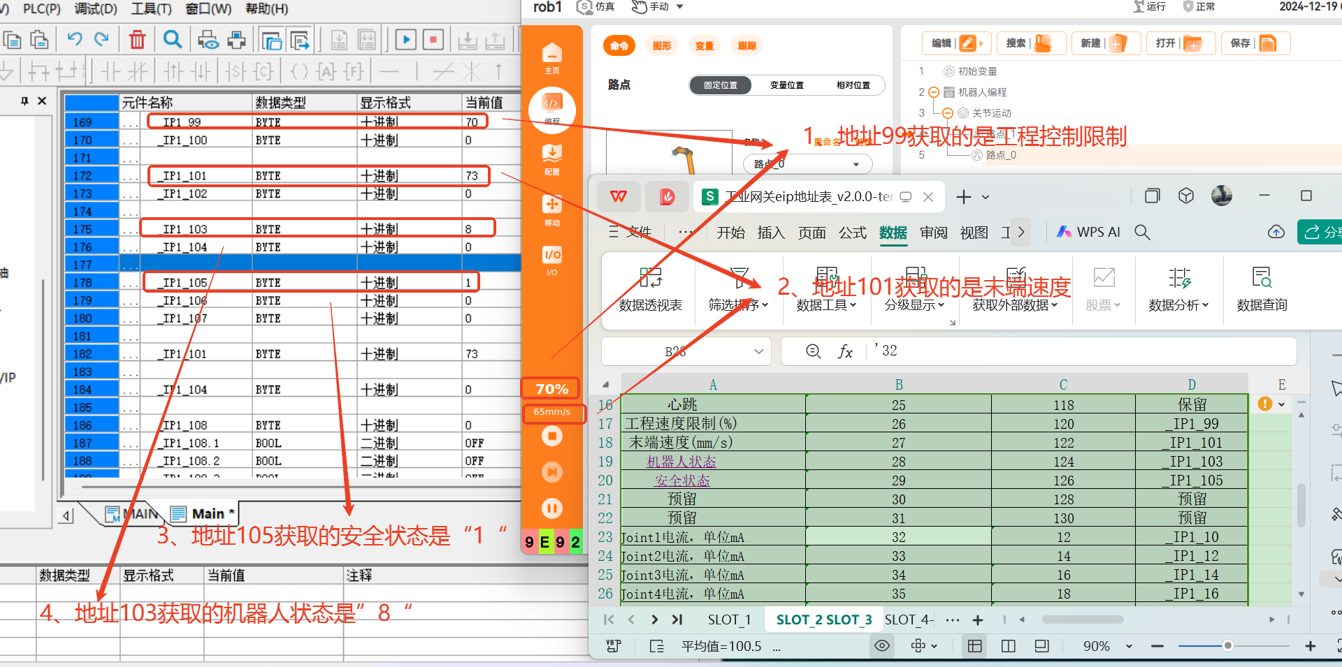
6.4 Application of Soft EIP in Omron PLC
6.4.1 Preparation for configuring the environment
6.4.1.1 Preparation for configuring the environment
Software Preparation:
- Sysmac Studio software version:
V1.52.0.64010. - Please contact AUBO developers to download the EDS file:
compatible_eip_slave_v0.0.1.eds. - ARCS software versions: 0.29.3-rc.9 and above, 0.31.0-beta.1 and above, 0.32.0-alpha.9 and above.
- Sysmac Studio software version:
Hardware Preparation:
- Omron
NX1P2-9024DT - Mechanical arm body
- Laptop
- Network cable
- HUB or switch
- Omron
network cable
Modify the configuration file
aubo_control.confand add the following code:eip_enable = true eip_ifname = "enp1s0" #Change the network card name according to the actual situation
6.4.1.2 Hardware wiring
Connect the PLC, control cabinet, and local computer to the same network via a switch. After the wiring is completed, it is necessary to use the ping command to test whether the PLC IP, control cabinet IP, and local IP can communicate with each other. Only after confirming that the network communication is normal can the subsequent operations be carried out.
6.4.1.3 PLC sets static IP
Double-click to open the Sysmac Studio software and enter the home screen. If you have configured the PLC before and created and saved the previous project, you can directly click the "Online > Link to Device" option. In the dialog box, select the connection type as [Ethernet-Hub Connection], set the IP address in the connection settings to 192.168.250.1, and then click [Connect]. If you have not configured the PLC or created a new project yet, skip this step.
Click the [New Project] option directly to pop up a dialog box, fill in the project name, and select the Omron PLC model
NX1P2-9024DT; then click [Create] to create a new project.After entering the main interface of the Sysmac Studio software, click "Control > Communication Settings" to bring up the Communication Settings dialog box. In the dialog box, select the connection type as [Ethernet-Hub Connection], configure the IP address in the connection settings to
192.168.250.1, and then click [Ethernet Communication Test]. If the communication is successful, click [OK] to proceed with the subsequent operations; if the communication fails, reset the PLC address.If communication failure is found when testing communication with the PLC, it is necessary to reset the IP address of the PLC. Click "Configuration and Settings > Configuration and Settings" in the left directory tree to enter the port settings page. In the IP address option, select a fixed IP address and fill in the IP and subnet mask. Generally, the default IP address of Omron PLC is 192.168.250.1 and the subnet mask is 255.255.255.0, which can be used directly without modification.
After the settings are completed, click "Tools > Update Configuration and Set Transfer Data" to update the configuration to the PLC.
6.4.1.4 Set a static IP for the robotic arm
Open the ARCS software homepage, click "Settings > System > Network > Static Address" in the left navigation bar to set a static IP. The static IP address needs to be in the same network segment as the PLC and the laptop.
6.4.1.5 PLC imports EDS file
Click "Tools > EtherNet/IP Connection Settings" to display the list of EtherNet/IP devices. Double-click the target PLC device in the device list to open [Built-in EtherNet/IP Port Settings Connection Settings] and configure the relevant connection settings.
Click "Toolbox > Target Device" on the right side. If the eds file has not been loaded, the target device will not be displayed. Right-click on the blank area, a menu will pop up, and select [Show eds Library].
After clicking [Show EDS Library], a dialog box for importing EDS files will pop up. Click [Install] and select the pre-prepared EDS file; then, the loaded
Aubo Robotwill be displayed in the [Vendor] list. Click [Close].
6.4.1.6 Device Station IP Settings
Click the add button to add the target device.
In the toolbox displayed on the right, enter the node address (the IP address of the EIP service, which is the IP address of the robot), enter
Aubo Robotfor the model name, and enter 2 for the revision; then click the [Add] button to add the target device.
6.4.1.7 Connection settings between PLC and device stack
- Add global variables. In the left directory tree, click [Programming] -> [Data] -> [Global Variables] to enter the global variable settings page and add input and output variables.
- Click the tab to switch the page to [Built-in Ethernet/IP Port Settings - Connection Settings]. First, check whether the device information is correct, mainly looking at the model name and node address. Then start adding tag groups. Click the [Register All] button, and the [Tag Group Registration Settings Dialog Box] will pop up.
- In the [Tag Group Registration Settings Dialog Box], select the input tag and output tag, then click the [Register] button.
- Switch to the Connection tab page, click the Add button, add a connection, and then set it according to the corresponding connection parameters.
6.4.1.8 Save Project > Transfer to Controller > Run > Monitor
After all configurations are completed, save the project, click the [Online] button, then click [Transfer to Controller]. A "Transfer to Controller" dialog box will pop up. After selecting "Yes", the connection configuration will be downloaded to the PLC.
After clicking "Run > Monitor", you can start monitoring changes in the signal values of relevant addresses. Click [Monitor (Project)] to start adding signals.
Add some example signals. If the robot's status can be read and the robot's speed can be set, it indicates that there is no problem with the PLC > Robot and Robot > PLC communication.
6.4.2 Example of PLC communication with controller
Using the EIP protocol, as can be seen from the address table, the contents included in the communication between the PLC and the robotic arm are:
- Robot Arm IO Status (slot_1)
- Robot arm pose (slot_2)
- Robot arm joint current, voltage, temperature (slot_3)
- General coils and general holding registers (slot_4, slot_5)
Among them, slot_1, slot_2, and slot_3 can be directly read through the PLC. slot_4 and slot_5 contain the contents of coils and holding registers, and the communication between the PLC and the robotic arm is realized through the ARCS system script call.
6.4.2.1 Universal Coil (Robot > PLC)
setBoolOutput(0, true), sets the first bool quantity at the starting address of PLC slot_4 to true. According to the address of the first general coil (Robot > PLC) in the address table, add the monitoring address to the monitoring (engineering) table in the Sysmac Studio software.
6.4.2.2 General Holding Register (Robot > PLC)
setInt16Register(32, 183) ,writes the value 183 into the first data of the PLC slot_4 holding register (with the 9th byte of slot_4 as the starting address of the holding register). Here, the starting address of setInt16Register is 32. After 1 second, change the data to 99. According to the address of the first general-purpose register (Robot > PLC) in the address table, add the monitoring address to the monitoring (engineering) table in the Sysmac Studio software.
6.4.2.3 Universal Coil (PLC > Robot)
According to the address of the first general-purpose coil (PLC => Robot) in the address table, add the monitoring address in the monitoring (engineering) table of the Sysmac Studio software and write the value. bool0 = getBoolInput(0) reads the first bool quantity from the starting address of PLC slot_5 and saves it in the variable bool0.
6.4.2.4 Universal Holding Register (PLC > Robot)
According to the address of the first general register (PLC > Robot) in the address table, add the monitoring address in the monitoring (project) table of the Sysmac Studio software and write the value. tmp0 = getInt16Register(0), the robot reads the first register (16Bit) starting from the 9th byte of PLC slot_5 and saves it in the variable tmp0.
7. Frequently Asked Questions
7.1 Common Questions about Profinet
Question: Confusing the robot's IP with the Profinet slave's IP.
Solution: The IP set on the teach pendant interface and the IP configured for Profinet in the TIA Portal software must not be the same; otherwise, connection failures or inability to connect to the external network may occur. You can modify the IP displayed on the teach pendant to another one within the same network segment.
Question: The configured slave name is different from the actual name.
Solution: It is necessary to unify the name of the Slave Station with the configured name in the TIA Portal software, and there should be no Slave Stations with the same name in the same local area network.
Question: Incorrect modification of the configuration file.
Solution:
- Solution: It is necessary to unify the name of the Slave Station with the configured name in the TIA Portal software, and there should be no Slave Stations with the same name in the same local area network.
- The configuration of the
network_portnetwork interface option in the configuration file is incorrect. The default value isenp1s0with single quotes. - The configuration of gsd_type in the configuration file is incorrect. Initially, only 2 options are supported, which is the address table compatible with industrial gateways.
Question: The GSD file failed to be imported.
Solution: Please check whether the GSD file used is dedicated to the Profinet plugin (included in the compression package).
Question: For different control cabinets, do the default network ports need to be modified?
Solution: If you are unsure about the currently used network port, enter
ifconfigin the terminal of the control cabinet. Find the network port whose IP is the control cabinet's IP, modify this network port into the configuration file/root/arcs_ws/config/pn_server.conf, and restart Profinet. For example, the improved control cabinet needs to change the defaultenp1s0toenp2s0; the C-type control cabinet needs to be modified according to the actual inserted network port; and the iS control cabinet does not need to be changed.Question: After the Profinet slave service is turned on, the status shows not connected. How to fix it?
Solution: First, check whether the network cables of the PLC and the robotic arm are properly connected and whether they can ping each other. If the communication is normal, open the terminal, enter the command: systemctl restart pn_server, and restart the ARCS software, which will then show a normal connection.
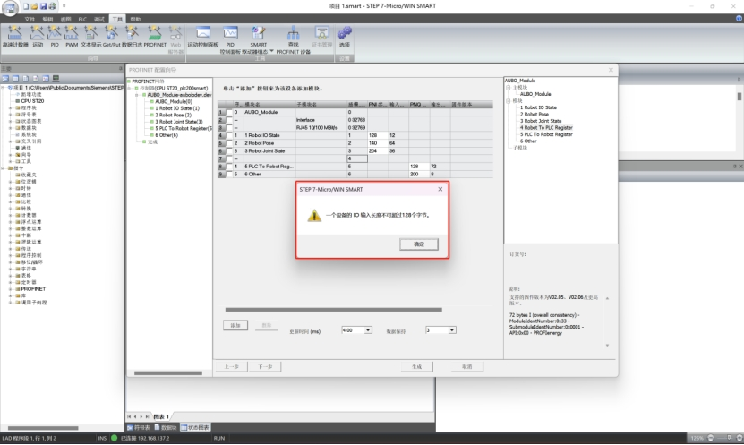
Question: How to fix the abnormal display in STEP-7 Micro/WIN SMART software when a PLC (s7-200 smart plc) is connected to a Profinet slave?
Solution: The appearance of the following pop-up window indicates that the memory of the PLC is insufficient. Taking the following figure as an example, this PLC allows a maximum input of 128 bytes of data. However, the total from slot 1 to slot 4 exceeds 128 bytes, so this pop-up window will appear when dragging into slot 4, and slot 4 cannot be loaded correctly. The solution is to replace the PLC with a better performance and configuration, or delete the unnecessary slots and only load the required ones.
7.2 Common Questions about Modbus
Question: When using a wireless teach pendant, if a router is used to bridge the network, there may be a situation where the IP can be pinged, but the Modbus master signal is not connected.
Solution: Check if the router is configured with port forwarding. If not, you need to configure the port number used by Modbus TCP.
Question: Modbus RTU signal communication failed.
Problem Analysis:
To check whether the serial communication between the device and the robot is normal, you can use the serial port debugging assistant in the device and the robot to test the serial communication status.
Check whether the signal address established by the Master Station exists in the Slave Station. The address corresponding to the newly created signal by the Master Station must exist in the Slave Station for the signal to communicate normally.
Solution:
- Use the command to install
cutecomin the robot control cabinet.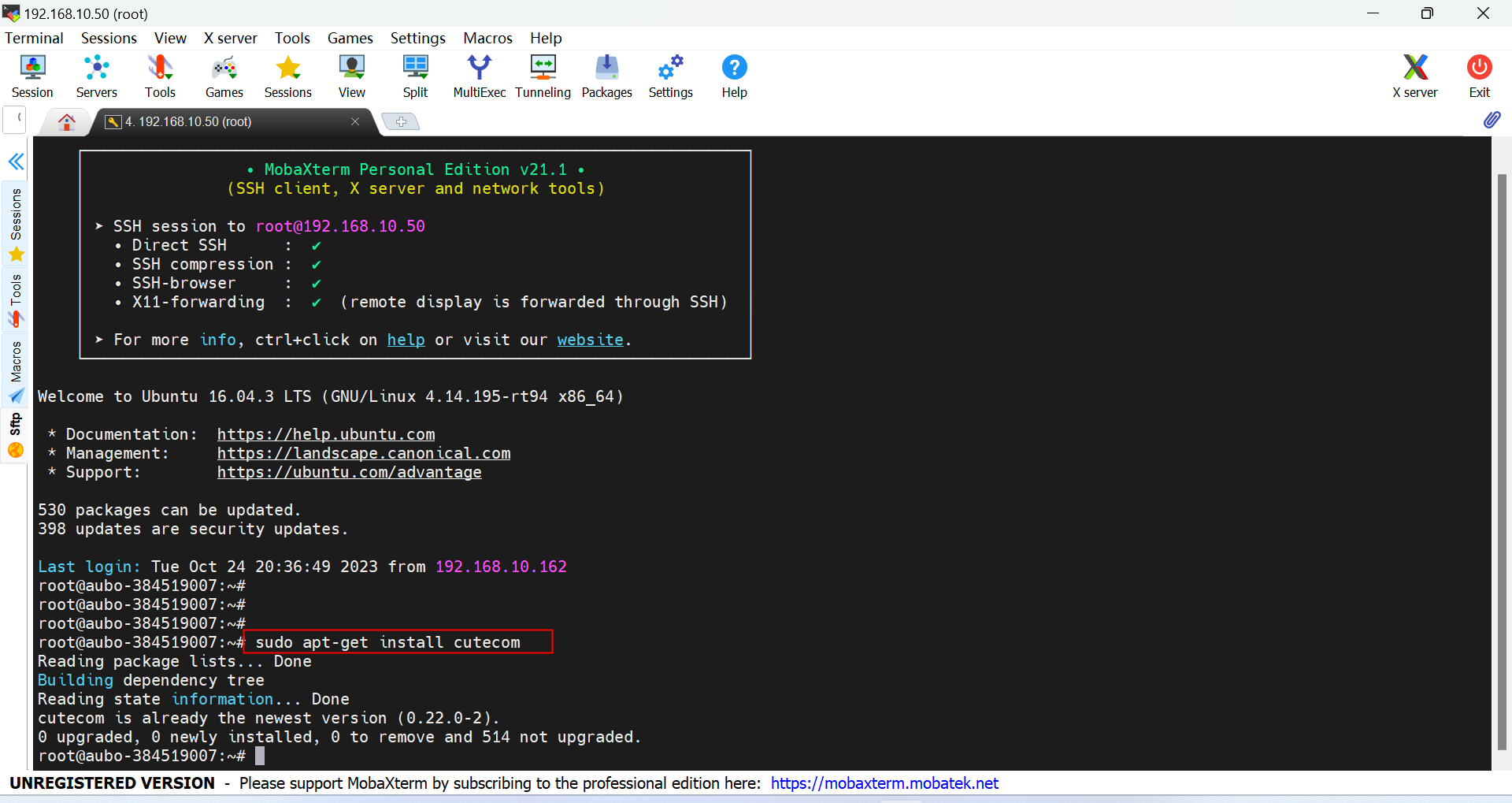
- Open cutecom and set the [Serial Port Number], [Baud Rate], [Parity Check], [Data Bits], and [Stop Bits].
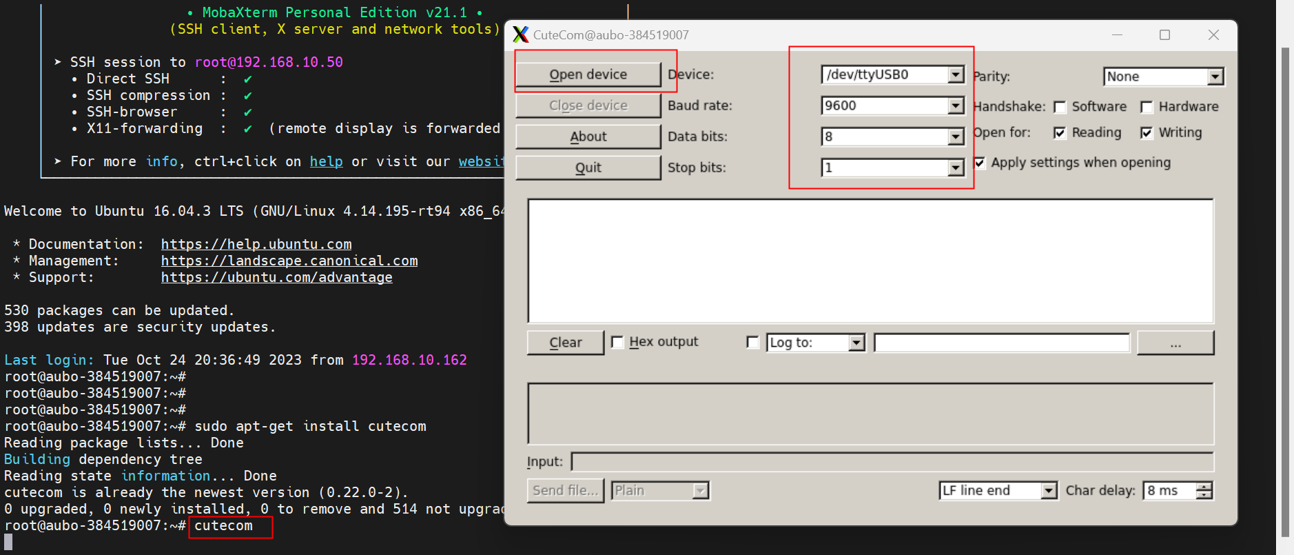
- If the device is a PLC, use
cutecomto directly connect to the PLC for testing. If the device is the local computer, you can install a serial port debugging assistant on the computer, such asXCOM.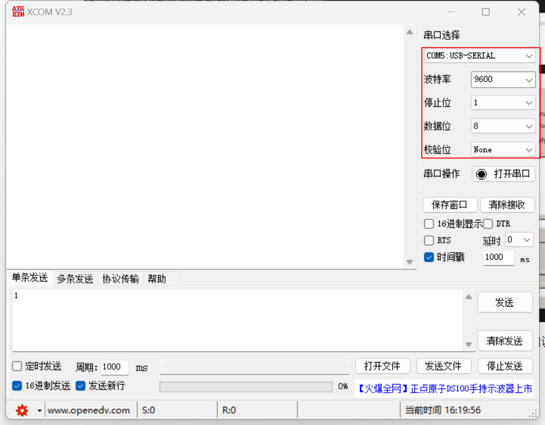
- If
cutecomandPLC/XCOMcan send data to each other, it indicates normal communication and that there is no problem with the serial communication line. Conversely, it is necessary to check the connection status of the communication line.
Question: How to solve the failure of Modbus TCP signal communication? Solution:
- To check whether the network between the device and the robot can communicate normally, first check if the device's firewall is turned off, and then use the
pingcommand to check if the network can communicate normally. - Check whether the signal addresses established by the Master Station exist in the Slave Station. Only when the addresses corresponding to the new signals of the Master Station exist in the Slave Station can the signals communicate normally.
- Check if the robot's IP address is the same as that of other devices in the same local area network and if there is a conflict.
- To check whether the network between the device and the robot can communicate normally, first check if the device's firewall is turned off, and then use the
7.3 Common Questions about EIP
Question: What should I do if modifying the PLC address fails?
Solution:
- Check if the hardware wiring is correct, if the network cable is loose, and if the power cables of the switch and PLC are loose.
- Connect the laptop and PLC via a Type-C to USB adapter, and modify the IP address of the PLC.
Question: What to do if the target device is offline?
Solution:
- Check the network cable connection and whether the IP setting of the PLC is in the same network segment as the laptop.
- Use the PING tool to test whether the network between the PLC and the laptop can ping each other normally.
- Restart
AutoShopand reconnect for testing.
Question: What should I do if I can't find the
SYS_EIPaddress?Solution:
- The address in
SYS_EIPis imported according to the EDS file, and the address is pre-allocated by developers based on the EIP address table. - Under [EtherNet/IP], delete [Auto_Robot], then delete the EDS file and re-import it.
- Double-click to add [Auto_Robot], delete the original connection, and re-add the connection.
- Download PLC, click "Run > Monitor", and check if the
SYS_EIPaddress can be found. - If the above issues are not resolved, restart the control cabinet and the AutoShop software, and repeat the above steps.
- The address in
Question: The communication is successful, but why is there an error in reading the data?
Solution:
- The data does not change, but the result is incorrect. It is necessary to check whether the address of the variable monitoring table is consistent with the EIP address table.
- The data changes, but the result is incorrect. If the address is two bytes, the data composed of the two bytes must all be sent (for example, the address of the end velocity and robot status is two bytes). If the address to be obtained is four bytes, the data composed of the four bytes must all be read (for example: position coordinates and joint angles are four bytes).
8. Summary
This industrial bus technology manual comprehensively introduces three mainstream industrial bus technologies: Profinet, Modbus, and EIP (Ethernet/IP). Through studying this manual, you should be able to:
- Understand the basic concepts and working principles of industrial buses.
- Master the configuration methods and usage skills of three mainstream industrial buses.
- Learn about the network basics and hardware preparation for industrial buses.
- Master the general configuration process and troubleshooting methods of industrial buses.
- Be able to select appropriate industrial bus technologies according to actual application scenarios.
8.1 Suggestions for technology selection
- Profinet: Suitable for complex automation systems with high real-time requirements, such as automobile manufacturing, electronic assembly, etc.
- Modbus: Suitable for simple control systems with low real-time requirements, such as packaging machinery, logistics transportation, etc.
- EIP: Suitable for scenarios requiring integration of multi-vendor equipment, such as production line transformation, equipment upgrading, etc.
8.2 Future development trends
With the advancement of Industry 4.0 and intelligent manufacturing, industrial bus technology is also constantly evolving:
- High-speed: Communication rates are evolving from 100 megabits to gigabits or even 10 gigabits.
- Wireless: The application of industrial wireless communication technologies is becoming increasingly widespread.
- Intelligent: Industrial bus technologies that support edge computing and artificial intelligence.
- Standardized: Unified industrial communication standards and protocols.
This manual will be continuously updated to provide you with the latest information on industrial bus technologies and application guidelines.