
Force Control Application Manual
1 Introduction
This manual is intended for technical personnel involved in the design, commissioning, maintenance, and selection of industrial automation systems. It provides a structured overview of force control technology, covering operating principles, hardware selection, system configuration, commissioning, troubleshooting, and application integration; serving as a practical guide for new users and technical reference for experienced engineers.
2 Safety Information
Force control systems involve robot motion and force-sensing devices and therefore present inherent safety risks. Before use, users must carefully read, understand, and follow the instructions in this manual. System integrators must ensure that force control systems comply with applicable laws, regulations, and industry standards. Risk assessments and safety measures must be implemented to minimize hazards. Users must also comply with all safety requirements specified by the system integrator.
AUBO WARNING
During the deployment and operation of the force control systems, users are responsible for the safety of personnel and equipment. AUBO assumes no liability for accidents or damages resulting from improper operation or failure to comply with applicable safety regulations.
3 Force Control Principles
3.1 Introduction to Force Control
Force control is the core technology that enables compliant interaction between industrial robots and their environment. By acquiring contact force signals from force/torque sensors and processing them with control algorithms, the robot adjusts its trajectory and pose in real time, enabling the end effector to maintain controllable contact force during contact tasks.
3.1.1 Types of Force Control
| Type | Key Characteristics | Typical Applications |
|---|---|---|
| Active Force Control | Acquires force signals in real time and actively adjusts robot motion using closed-loop control to maintain the desired contact force. | Grinding, assembly, insertion/removal tasks, fabric ironing |
| Passive Force Control | Achieves compliance through mechanical elements (e.g., springs and dampers) to passively absorb contact forces without real-time feedback control. | Basic grasping, low-precision assembly |
| Hybrid Force Control | Combines active and passive force control. Active control is applied along the primary axes, while passive compliance is provided along the remaining axes. | High-precision gear meshing, waterproof cover installation |
3.1.2 Typical Application Scenarios
Assembly Applications: Gear assembly, USB insertion/removal, and waterproof cover installation (key requirements: precise positioning with controlled contact force to prevent component damage).
Surface Processing Applications: Grinding, fabric ironing, and touch screen drawing (key requirements: force compliance with trajectory tracking to ensure consistent processing quality).
Inspection Applications: Workpiece dimensional inspection and contact force calibration (key requirements: force control accuracy within ±0.5 N to ensure repeatable measurements).
3.2 Principles of Force Control
Force control is essentially closed-loop regulation between force and position. The core workflow is as follows: measure actual contact force > calculate the force error > convert it into a position or velocity correction offset > actuate robot motion accordingly.
The core principles of force control are summarized below.
| Control Mode | Operating Principle | Key Advantages | Typical applications |
|---|---|---|---|
| Force Feedback Control | 1. The actual contact force 2. The force error is calculated as 3. Based on 4. The robot moves | High force-control accuracy (±0.1~0.5 N) | Rigid / semi-rigid environments |
| Impedance Control | The robot end effector is modelled as a "mass–damping–stiffness" system. By adjusting the | Robust to environmental disturbances | Compliant environment (e.g., fabric and rubber) |
| Hybrid Position/Force Control | In the Cartesian coordinate system, some axes (e.g., the Z-axis) operate under force control, while others (e.g., the X- and Y-axes) operate under position control. | Balances trajectory accuracy with compliant force control. | Constant-force planar tasks (e.g., touchscreen drawing) |
Note:
: The actual contact force at the end effector measured by the force sensor. : The target force command issued by the controller. : The difference in value between the target force and the measured force. : The end-effector position correction calculated by the controller based on the force error. Compliant Control Algorithm: Based on the admittance model
the controller computes the required position correction .
3.3 Force Control Strategies
3.3.1 Comparison of Control Strategies
| Control Strategy | Control Logic | Tuning Difficulty | Force Control Accuracy | Typical Applications | Typical Parameter Settings (Z-axis) |
|---|---|---|---|---|---|
| Position Based Force Control Mode | Contact force regulated by adjusting position | Low | ±1~2 N | Rigid environments and low-precision tasks (e.g. simple pressing) | |
| Force Control Mode | Direct closed-loop force control with adaptive position compensation | Medium | ±0.5~1 N | Compliant environments and constant-force tasks (e.g. fabric ironing) | |
| Impedance Control Mode | Adjusts | High | ±0.1~0.5 N | High-precision tasks (e.g. touchscreen drawing, gear meshing) | |
| Hybrid Control Mode | Position control in the X/Y axes with force control in the Z-axis | Medium | ±0.5 N | Planar constant-force trajectory tasks (e.g., drawing straight lines or circles) | X/Y: Z: |
3.3.2 Practical Guidelines for Switching Strategy
Rigid > compliant environment: Decrease
(stiffness) and increase (damping) to suppress force overshoot during environment transition. Low > high precision: Reduce
(virtual mass) and tighten the force error threshold (e.g., from ±1 N to ±0.2 N). Single-point > trajectory-based tasks: Enable hybrid force/position control to maintain positioning accuracy along the trajectory axes (X/Y) while maintaining compliance along the force-controlled axis (Z).
3.4 Force Control Parameter Tuning
3.4.1 Engineering Definition of Key Parameters
| Parameter | Engineering Definition | Tuning Direction |
|---|---|---|
| Determines the apparent inertia of the robot end effector. A larger | High speed applications: Decrease High precision applications: Moderately increase | |
| Determines the motion damping of the robot end effector. A larger | Excessive force overshoot: Increase Slow response: Decrease | |
| Determines the restoring force of the robot end effector. A larger | Applications/tasks that require compliance (floating behavior): Precise positioning: Increase | |
| Target Force | Should be determined according to the application scenario, with an appropriate "safety margin" reserved (For example, if the maximum allowable force for a touchscreen is 1.5 N, the target force should be set to 1 N.) | Fragile workpieces: Decrease target force Rigid workpieces: Moderately increase |
3.4.2 Parameter Tuning Procedure
Initial parameter settings
Mass
: Set the initial values for all six axes to {20,20,20,10,10,10}(Recommended baseline values are suitable for most compliant applications.)Damping
: Set the initial values for all six axes to {500,500,500,100,100,100}(To avoid initial force overshoot).Stiffness
: Set the force-control axis to 0 and the position-controlled axis to 1000 (Prioritise a stable position before applying force). Target force: Set to 70% of the required task force (e.g., if the required force is 10 N, initially set it to 7 N to reduce initial contact force).
Damping
tuning (prioritize eliminating force overshoot) Run the task programme and observe the force profile.
If the force overshoot > 20% (e.g. target force 10 N, peak force 12 N+): increase D by 10% until the overshoot is ≤ 10%.
If the force response time > 500 ms: Decrease D by 5% until the response time ≤ 300 ms.
Mass
tuning (optimize dynamic response) If trajectory error > 0.5 mm: Decrease
(10% each time), until the trajectory error ≤ 0.2 mm. If force fluctuation >±0.5 N: Increase
(10% each time), until the fluctuation ≤ ±0.2 N.
Stiffness
tuning (application specific) Floating operation: Set
=0 to allow the end effector to move freely under external forces (e.g., hole searching). Return-to-Position Operation: Gradually increase
(200 each time) until the positioning accuracy ≤ 0.1 mm (e.g., returns to the original position after tapping). Compliant contact: Set
to 0 to avoid the "spring effect" that may damage the workpiece (e.g., fabric ironing).
Target force calibration
- Gradually increase the target force to the required value (1 N each time) while monitoring force stability. If overshoot occurs, readjust the
parameters.
- Gradually increase the target force to the required value (1 N each time) while monitoring force stability. If overshoot occurs, readjust the
3.5 Force Control Effects and Applications
Different parameter settings allow force control to achieve the following effects:
Dragging Effect: When
is 0 and no target force is specified, the robot arm enters a drag mode. When an external force is applied to the end effector, the robot arm moves in the direction of the applied force and will not return to its original position. Spring Effect: When
is not 0 and no target force is specified, the end effector behaves like a spring. The larger the value of K, the stiffer the virtual spring. Consequently, a larger force is required to move the end effector away from its current position. Once the external force is removed, the robot arm returns to its original position. Force Guidance Effect: When
is 0, with and a target force specified, the robot arm exhibits force-guided motion. Without any external force applied, the robot arm continues to move. Its speed is proportional to the force error and inversely proportional to the damping coefficient, until the force applied in the opposite direction balances the target force. Spring Effect with Target Force: When
is not 0, with and a target force specified, the robot arm first displaces by a certain distance. It then stops while maintaining a virtual spring state. The force required to resist this displacement equals the specified target force.
4 Force Sensor Selection and Installation
4.1 Types of Force Sensors
Force sensors are a key component of force control systems and can be broadly classified into the following types:
Built-in force sensor: A force sensor built into the robot end effector for measuring end-effector contact force.
External force sensor: A force sensor installed on the robot end-effector for measuring end-effector contact force.
Externally connected force sensor: A force sensor connected to the robot controller (via an RS-485 interface or a USB-to-RS-485 adapter). Driver parameters must be configured and the corresponding plugin installed before the sensor can be used for contact force measurement.
Typical Force Sensor Specifications:
| Parameter | Description | Typical Value |
|---|---|---|
| Measurement Range | Range of force/torque values that the sensor can measure | ±100 N / ±10 Nm |
| Resolution | Smallest detectable change in force/torque | 0.1 N / 0.01 Nm |
| Sampling frequency | Frequency at which the sensor updates its data | 1000 Hz |
| Accuracy | Maximum deviation between the measured value and the true value | ±0.5% |
4.1.1 Sensor Models
Supported Sensor Models:
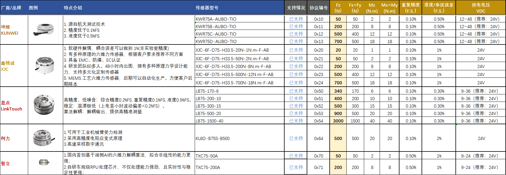
4.2 Force Sensor Installation
4.2.1 Built-in Force Sensor
Installation:
Built-in force sensor: The sensor requires no additional installation. It is ready for use after power-on.
Configuration:
For force sensor configuration, refer to 4.3 Force Sensor Configuration.
4.2.2 External Force Sensor
ARCS System Prerequisites
Before installing the sensor, verify the ARCS system version, hardware interface and sensor model to avoid sensor connection failures due to compatibility issues.
System Version and Protocol Verification
- ARCS system version ≥ v0.31.1
Hardware Interface Verification
Verify that the robot end effector provides a communication interface:
If an RS-485 interface is available on the end effector: Connect the sensor directly to the end-effector interface.
If no compatible interface is available on the end effector: Refer to 4.2.3 External Sensor Installation for the installation procedure.
Mechanical Installation of the External Sensor
Warning:
- Ensure that the robot arm is powered off before performing any wiring to prevent damage to the sensor or the robot interface due to short circuits.
- Before wiring, inspect the robot end-effector and sensor surfaces for damage or attached foreign debris. Ensure the mounting surfaces are flat and free of burrs.
Connect the sensor cable to the 4-pin circular connector on the robot end-effector.
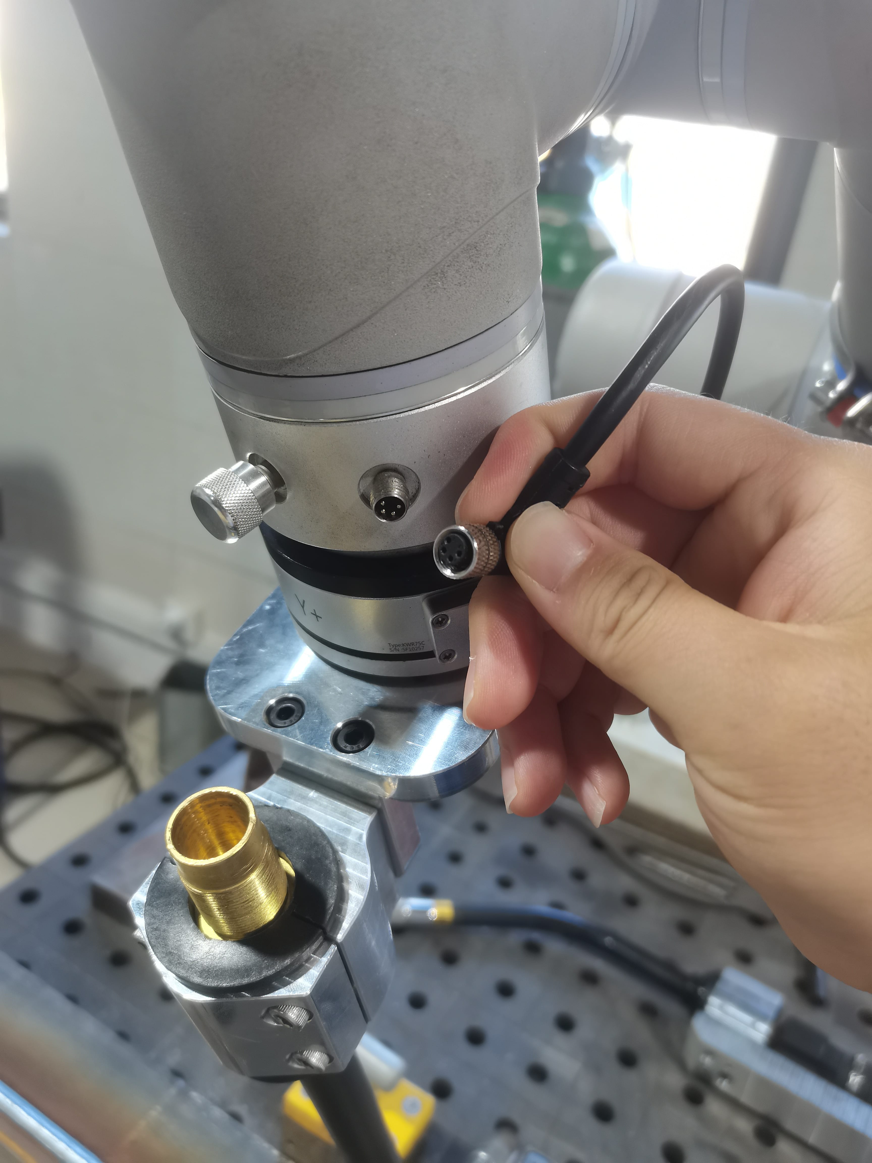
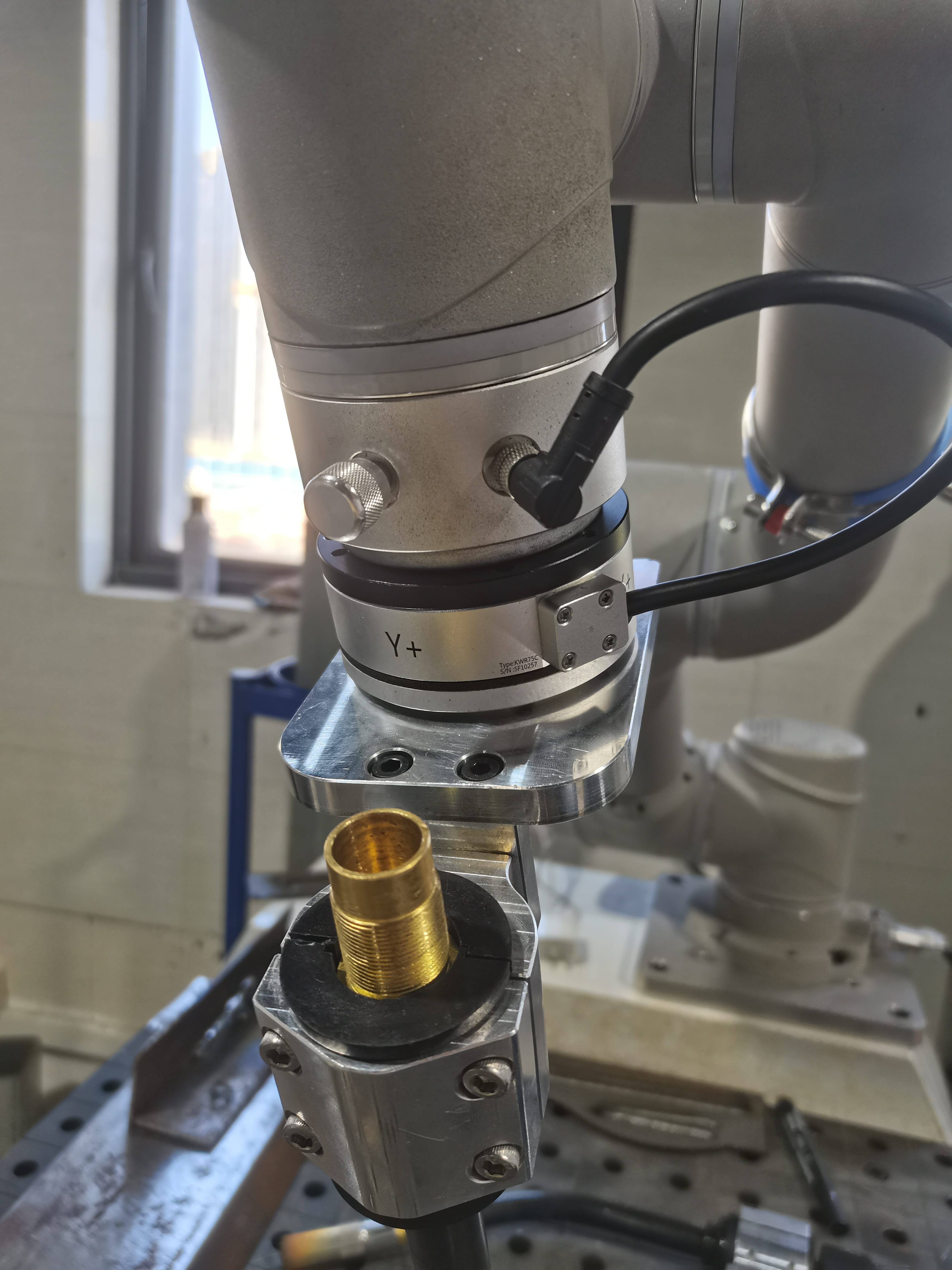
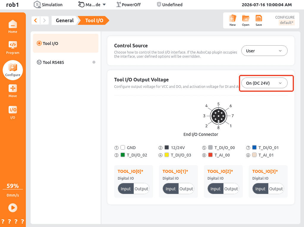
Sensor power supply: On the Tool I/O Configuration page, set the output voltage of the VCC and DO terminals to DC24V:
ARCS Configuration and Operation Procedure
Verify that the ARCS system version ≥ v0.31.1 (upgrade the system first if the version is too low).
Complete the mechanical installation of the sensor.
Configure the 24 V power supply on the Tool I/O Configuration page and verify that the sensor is communicating normally (sensor online).
Call the initialization API and select the sensor model.
After completing sensor calibration, the sensor is ready for use.
Note:
For force sensor configuration procedures, refer to 4.3 Force Sensor Configuration.
4.2.3 Externally Connected Force Sensor
An externally connected force sensor must be connected to the controller, and the corresponding configuration file must be modified to complete installation and configuration.
Mechanical Installation of the Externally Connected Force Sensor
WARNING
- Ensure all wiring operations are carried out with the controller powered off to prevent short circuits that may damage the force sensor or controller interface.
- After connecting the controller to the robot end-effector, ensure the fixing screws of the RS‑485 adapter are fully tightened to prevent poor electrical contact caused by loose fittings.
Wiring for the sensor USB-to-RS‑485 interface to the controller is shown below:
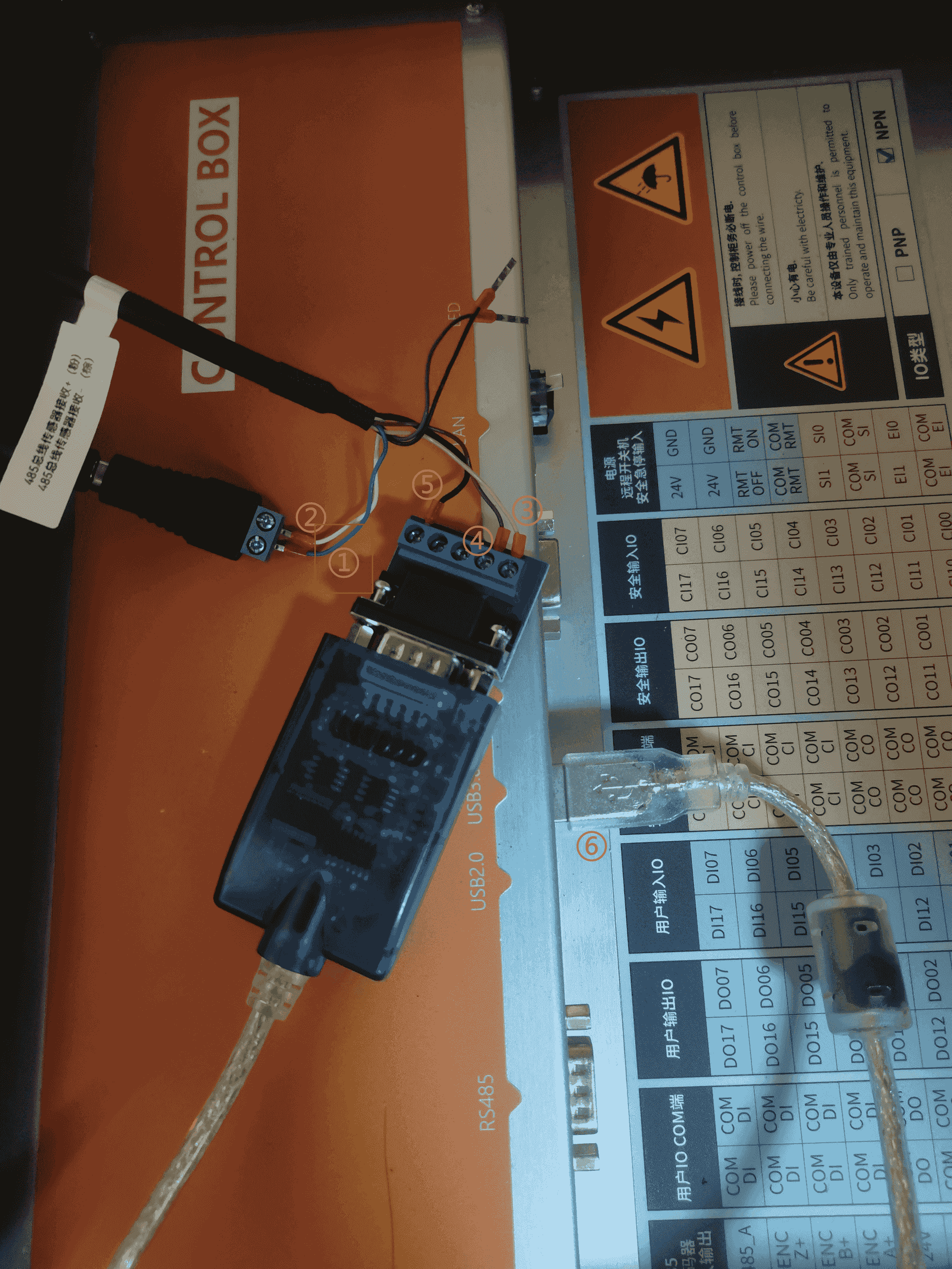
No. Description Method of Connection 1 Sensor power (+) Connect to an external power supply or the 24 V DC output on the controller I/O board. 2 Sensor power (−) Connect to an external power supply or the GND terminal on the controller I/O board. 3 RS485 communication (+) Connect to the T/R+ terminal of the USB-to-RS-485 module. 4 RS485 communication (−) Connect to the T/R− terminal of the USB-to-RS-485 module. 5 Shield wire Connect to the GND terminal of the USB-to-RS-485 module. 6 USB port of the USB-to-RS-485 module Connect to a USB port on the controller. Note:
- GND: Power ground / signal ground, the 0 V reference potential of the circuit.
- T/R+/-: Differential transmit/receive terminals of the USB-to-RS‑485 module (T/R+ is the positive signal line, T/R− is the negative signal line).
- RS‑485+/-: Differential RS‑485 communication signal terminals on the force sensor side (connect RS‑485+ to T/R+ and RS‑485− to T/R−).
- Shield wire: The metallic shielding layer of the communication cable, used to reduce electromagnetic interference (EMI) and ensure stable signal transmission.
Configuration File Modification:
Append the following configuration file to the end of:
/root/arcs_ws/config/aubo_control.confXinJingCheng Configuration
toml[[Sensor]] location = "extensions/xinjingcheng_ftsensor/xinjingcheng_ftsensor.so" bundle = "xinjingcheng_ftsensor" alias = "xinjingcheng_ftsensor" enable = true [Sensor.options] manufactory = "XinJingcheng" port = "/dev/ttyUSB0" baudrate = 115200 stop_bits = 1.0 parity = "none" enable_notch_filter = falseYuLi Configuration
toml# Configuration of yuli_ftsensor [[Sensor]] location = "extensions/yuli_ftsensor/yuli_ftsensor.so" bundle = "yuli_ftsensor" alias = "yuli_ftsensor" enable = true [Sensor.options] manufactory = "YuLi" port = "/dev/ttyUSB0" baudrate = 230400 stop_bits = 1.0 parity = "even" enable_notch_filter = falseATI Configuration
toml[[Sensor]] alias = 'ati_ftsensor1' bundle = 'ati_ftsensor' enable = true location = 'extensions/ati_ftsensor/ati_ftsensor.so' [Sensor.options] address="127.0.0.1" #Sensor's IP port=40000 # Sensor portKunWei Configuration
toml# Configuration of kw_ftsensor1 [[Sensor]] location = "extensions/kw_ftsensor/kw_ftsensor.so" bundle = "kw_ftsensor" alias = "kw_ftsensor1" enable = true [Sensor.options] manufactory = "KunWei" port = "/dev/ttyUSB0" baudrate = 460800 stop_bits = 1.0 parity = "none" enable_notch_filter = falseNote:
The Kunwei sensor configuration is factory preset and does not require manual configuration. This configuration is provided only for troubleshooting purposes, allowing you to verify that the default parameter settings are correct.
For deployment and commissioning of the force control plug-in, refer to 4.3.3 Configuration of Externally Connected Force Sensors.
4.3 Force Sensor Configuration
4.3.1 Built-in Force Sensor
Currently, AUBO iS(FT) series robotic arms are equipped with self-developed built-in force sensors. Relevant connection and configuration operations can be completed via the AUBO teach pendant.
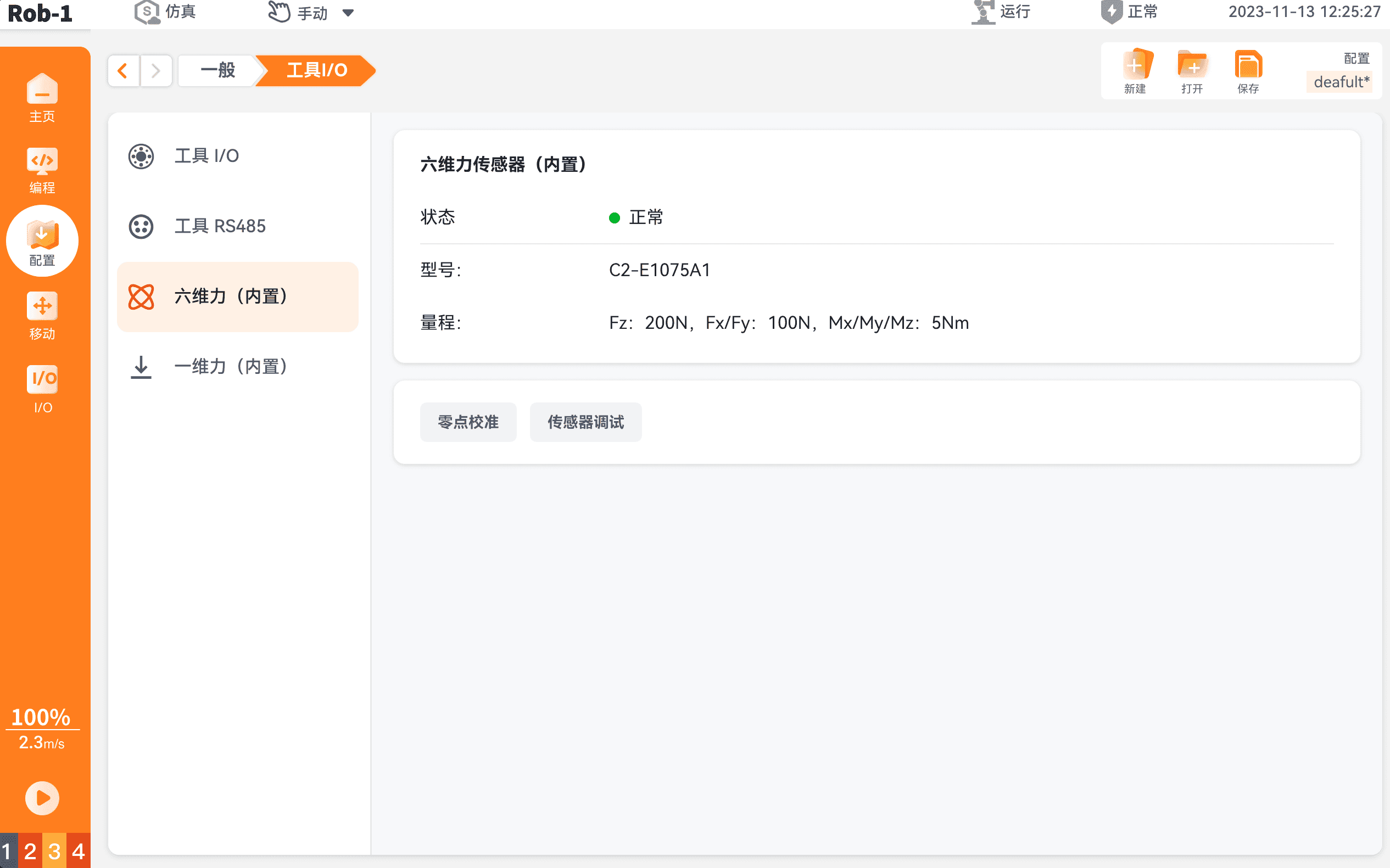
On the left navigation pane of the AUBO teach pendant, select "Configure > General > Tool I/O" to open the [Force Sensor Settings] page.
Built-in force sensors require no additional hardware connections. After power-on, the system automatically detects the sensor type and displays the corresponding [Force Sensor Settings] page.
Built-in Six-Axis Force Sensor
Status: Displays the current communication and operating status of the sensor. Typical status values include [Normal] and [Fault].
Model: Displays the hardware model of the built-in force sensor.
Measurement Range: Displays the maximum measurable load of the sensor in the six degrees of freedom (
, , , , and ). : Maximum axial force measurement range (e.g., 200 N). : Maximum radial force measurement range (e.g., 100 N). : Maximum measuring range for bending moments and torsional torque around each axis (e.g., 5 Nm).
Built-in Single-axis Force Sensor
Status: Displays the current connection status of the sensor. When [Connected] is displayed, it indicates that the system has successfully detected the hardware and data acquisition is available.
Measurement Range: Displays the maximum measurement range along the single axis.
: Maximum measurable force in the sensing direction (e.g., 200 N). This value defines the maximum compressive or tensile force that the sensor can measure along its primary load axis.
After the built-in force sensor has been configured, you can configure the [Zero Calibration] and [Force Sensor Settings] functions.
Note:
The procedures for configuring the [Zero Calibration] and [Force Sensor Settings] functions are identical for both built-in and external force sensors. Refer to the configuration procedure in Section 4.3.2.
4.3.2 External Force Sensor
The external force sensor mounted on the robot end effector can be configured directly through the AUBO teach pendant.
On the left navigation pane of the AUBO teach pendant, select "Configure > General > Tool I/O > Tool 485" to open the [External Force Sensor Diagnostics] page.
From the [Type] drop-down list, select [Six-Axis Force Sensor], then select the corresponding [Brand] and [Model] from their respective drop-down lists.
The [Installation Offset] is used to compensate for the offset between the sensor coordinate system and the flange coordinate system. After configuration is complete, click the button in the upper-right corner to activate the sensor.
Note:
The [Installation Offset] is typically set to 0. Currently, only the Yuli force sensor requires the [Installation Offset] to be set to 45°.
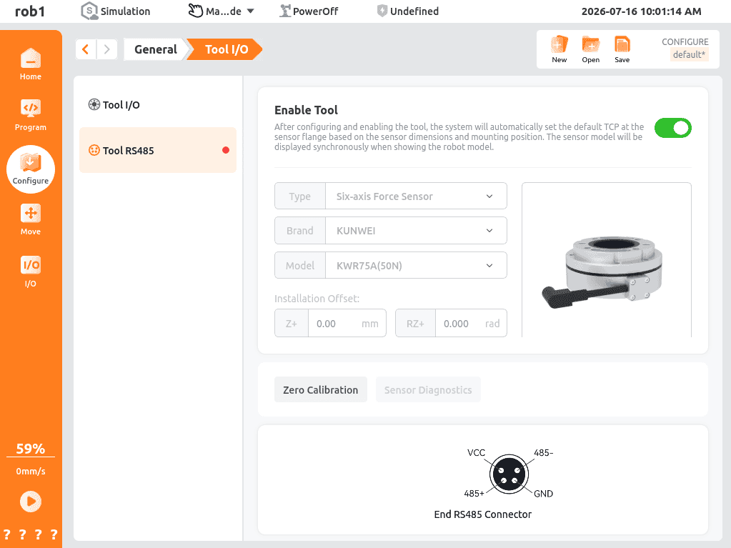
Six-Axis Force Sensor Tool Activation Status and Functions
After successful activation, the page displays as below:
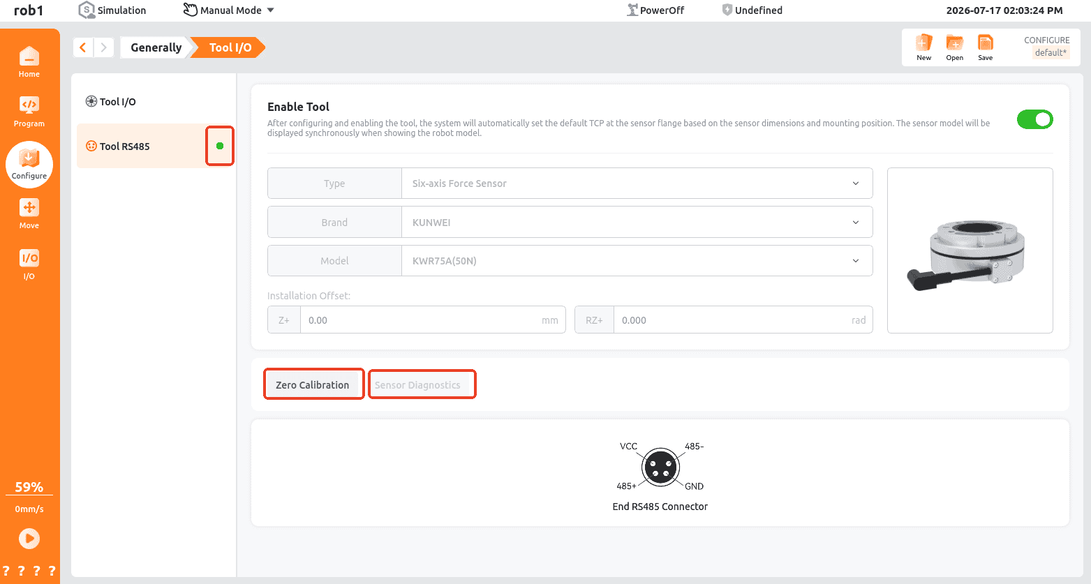
Activation Status: Gray indicates that the sensor is not activated, green indicates successful activation, and red indicates activation failure.
After successful activation, the [Zero Calibration] and [Sensor Diagnostics] buttons become available.
Zero Calibration:
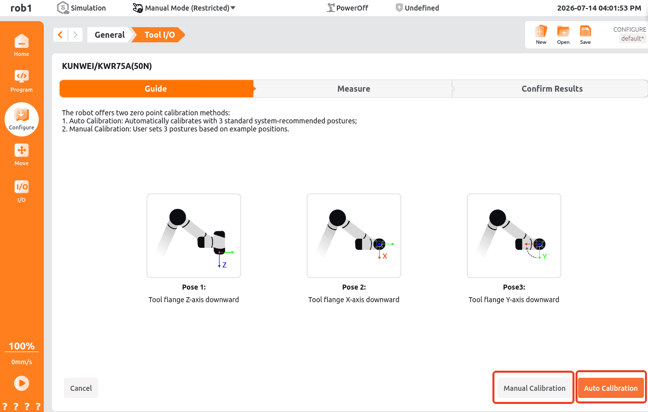
The [Zero Calibration] page displays the offset values from the most recent calibration. To recalibrate, click the [Recalibrate] button in the lower-right corner to enter the calibration page. Two calibration methods are available: automatic and manual calibration.
[Auto Calibration]: Calibration is performed automatically as the robot moves through three predefined poses. Ensure there are no obstacles or interference during the calibration process.
[Manual Calibration]: Follow the prompts to manually guide the robot through three poses, then start the calibration process.
Force Sensor Settings:
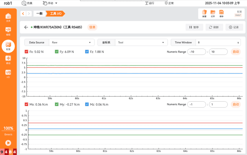
The [Force Sensor Settings] page is primarily used to view sensor data curves. It also allows for data recording, data playback, data type selection, coordinate system selection, and data display time configuration.
4.3.3 Externally Connected Force Sensor
An externally connected force sensor connected to the controller must be configured using the force control plug-in.
4.3.3.1 Force Control Plug-in Installation
Prerequisites: The ARCS software version must be
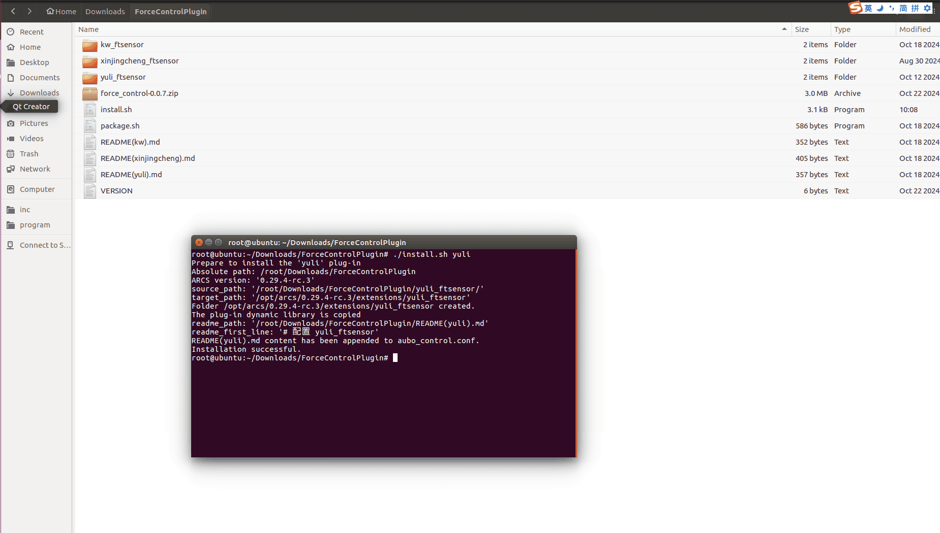
0.29.2-beta.15or later.Deployment: Contact AUBO technical support to obtain the plug-in package. After extracting the package, navigate to the extracted directory in a terminal and run the
sh install.sensor_typecommand (for example,sh install.kunwei) to deploy and configure the plug-in in a single step.Supported sensor brands: Kunwei, Xinjingcheng, Yuli, and ATI.
When the message shown in the figure below appears, the installation is complete.
Note:
After upgrading to a new version of ARCS for the first time, the plug-in must be redeployed.
4.3.3.2 Force Control Plug-in Deployment
Open the AUBO teach pendant, then select "Settings > System > Plug-ins > Add New". Select the plug-in package corresponding to the current software version, then click [Select] to add it.
After the plug-in has been added, enable the force control plug-in and click [Restart] to activate it.
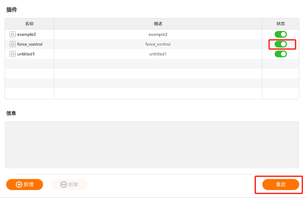
After the restart is complete, the force control plug-in will appear in the plug-in list.
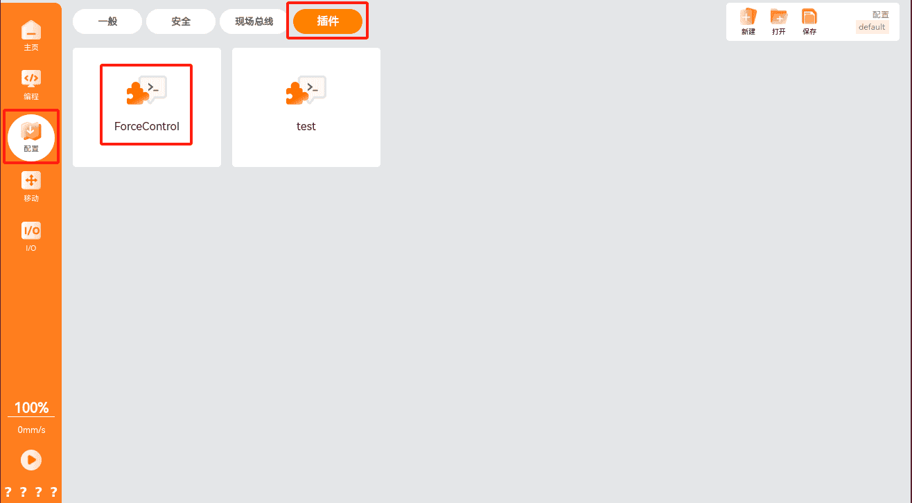
4.3.3.3 Force Control Plug-in Interface
Sensor Configuration Page
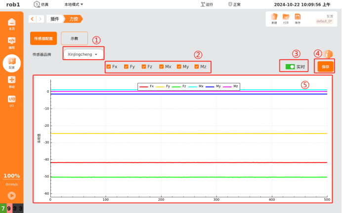
The sensor configuration page is shown above.
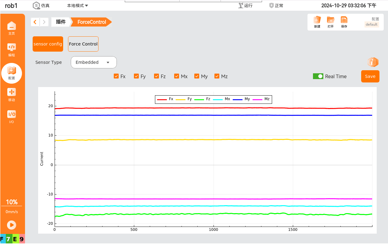
[Sensor Brand]: Used to select the sensor brand. Currently supports built-in, Kunwei, Yuli, and Xinjingcheng sensors. Once a sensor is selected, it immediately begins requesting data.
Use the checkboxes to show or hide the corresponding data.
[Real-time]: Select [Real-time] to display force data in the graph below.
[Save]:
When [Real-time] is not selected, clicking [Save] will save all data collected since the data request was initiated.
When [Real-time] is selected, clicking [Save] changes the button to [Stop] and begins saving data. Clicking [Stop] again ends the process of data saving. The saved data includes all data collected between the two button clicks.
Saved files are stored in the directory of
/root/arcs_ws/extensions/force_control. The first six groups of values in the file represent the TCP pose used, and the last six groups of values represent the force and torque along the X, Y, and Z axes.Note:
The file save path and graph display duration can be modified in the file:
/root/arcs_ws/program/default.ins. The configuration parameters are the same as the steps described above.The real-time graph displays force data in the Base coordinate system after offset and payload compensation. Six data channels are supported: Fx, Fy, Fz, Mx, My, and Mz, representing the force and moments about the X, Y, and Z axes, respectively.
Teach Pendant Page
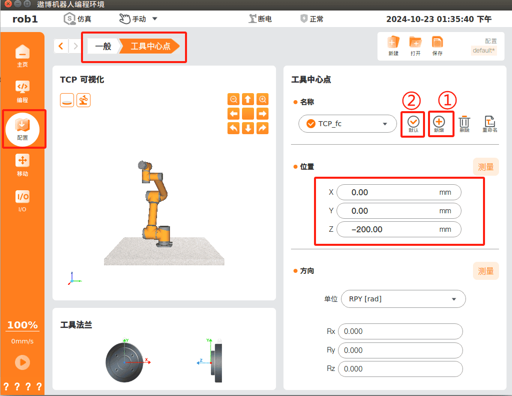
Before using the force control plug-in functions, add a TCP under "Configuration > General > Tool Center Point". Click [Add], enter the TCP offset relative to the flange center, and set this TCP as [Default], as shown below.
Next, calibrate the sensor by clicking [Calibrate] to start the automatic calibration process.
Note:
Before calibration, ensure that the sensor configuration page is receiving sensor data correctly. Also ensure that the robot is free from external interference or collisions during the calibration process. After calibration is complete, the parameter panel displays the offset, payload mass, and center-of-gravity data. Adjust the payload parameters as needed.
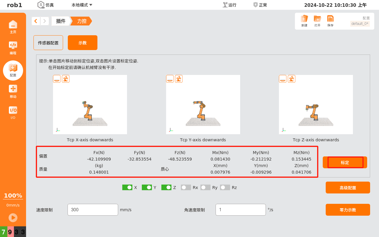
Calibration Pose Page
Three default calibration poses are provided: TCP X axis pointing downward, TCP Y axis pointing downward and TCP Z axis pointing downward, corresponding to the three images shown on the page.
Click one of the three images on the teach pendant page to navigate to the corresponding calibration pose page.
Double-click one of the three images to customize calibration pose. Move the robot to the desired pose, then click [Confirm] to save the new calibration pose automatically.
4.3.3.4 Force Control Plug-in Program Node
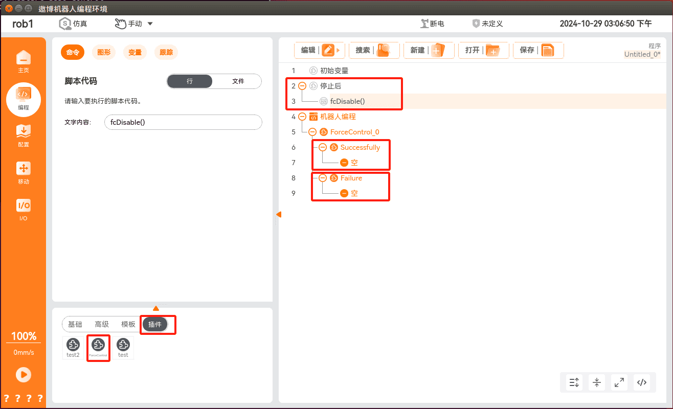
To add a force control node to the program, select "Programming > Plug-ins > ForceControl". This node provides two functions: Force Control Configuration and the program flow executed after a normal or abnormal exit from force control.
Note:
A workflow must be added for both normal and abnormal exits from the force control condition. In addition, when the program stops, the script should call fcDisable() to ensure that force control is disabled after an abnormal exit.
Basic Configuration
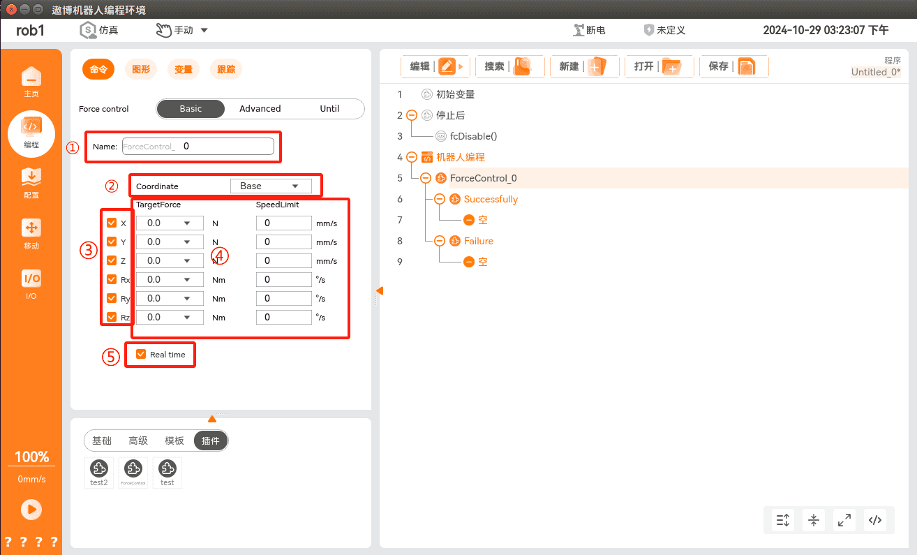
The node name can be customised.
Select the reference coordinate system. In most cases, the User Coordinate System or Tool Coordinate System should be selected.
Select the force control direction. If force control is not required in a particular direction, clear the corresponding checkbox.
Set the target force and corresponding speed limit.
View real-time force control data in "Configuration > Plug-ins > Force Control > Sensor Config", as shown below. The displayed reference coordinate system corresponds to the coordinate system selected in Step 2.
Advanced Configuration
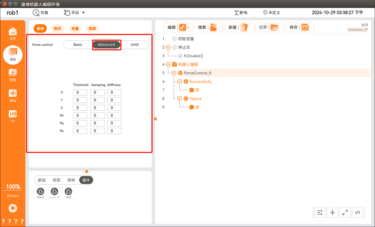
Use the [Advanced Configuration] page to configure the threshold, damping, and stiffness parameters for all six directions. Parameters for a given direction can be modified only if the corresponding checkbox is selected on the [Teach] page.
Threshold: Changes made to the threshold on this page do not take effect. To modify this parameter, edit the following file:
/root/arcs_ws/config/aubo_control.conf.Damping: Defines the resistance to robot motion. The damping force does not increase with the robot's displacement from the reference point. Instead, it generally increases with the robot velocity.
Stiffness: Defines the force with which the robot attempts to return to the reference point. A higher value produces a stronger spring effect. When this parameter is set to zero, no spring effect is generated, and the robot will move freely along the selected direction.
Stop Conditions Page
The [Stop Conditions] page consists of Normal Exit Conditions and Abnormal Exit Conditions.
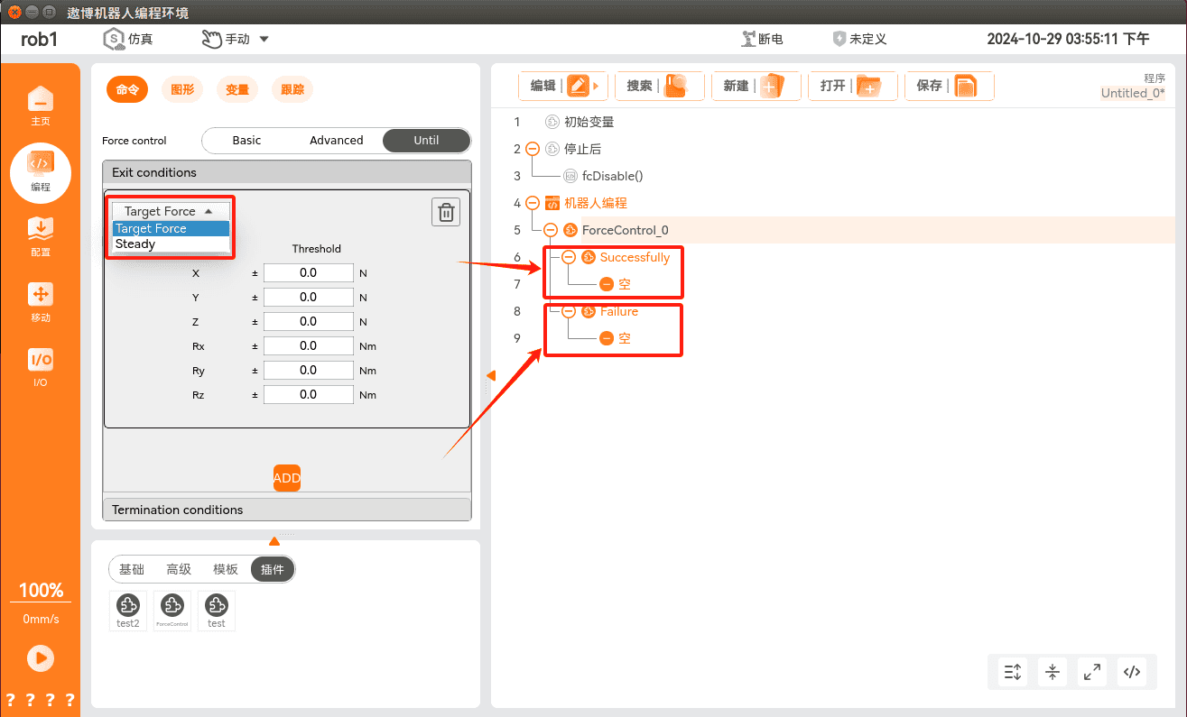
Under Normal Exit Conditions, two options are available: Target Force and Steady State. When either condition is satisfied, the force control plug-in exits and enters the normal force control exit procedure.
Target Force: Select this option when the measured force or torque along the six controlled axes reached the specified threshold.
Steady State: Select this option when the robot's motion queue is empty and the robot is stationary.
Under Abnormal Exit Conditions, the Timeout option is available. When the condition is satisfied, the force control plug-in exits and enters the abnormal force control exit procedure. Selecting Timeout means that the force control plug-in exits if the specified timeout period elapses after force control is enabled.
5 Force Control Programming
5.1 Force Control Program Node
Before configuring the Force Control Program Node, specify the robot arm task target. Click the [Configure] button in the upper-right corner of the program information panel to set the [Stiffness], [Damping], and [Environmental Stiffness] parameters.
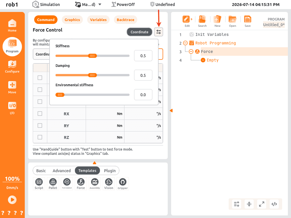
| Parameter | Description | Typical Applications |
|---|---|---|
| Stiffness | Defines the virtual spring coefficient used in force control, determining how rigidly the robot maintains the target position. Higher values produce a stiffer response with greater resistance to positional deviation, while lower values produce a more compliant response that is more easily displaced by external forces. | High stiffness (0.7~1.0): Precision press-fitting, rigid assembly, and positioning/welding tasks. Medium-low stiffness (0.1~0.6): Grinding, polishing, curved-surface tracking, and hand-guiding teaching |
| Damping | Defines the virtual damping coefficient used in force control to suppress vibration and oscillation, improving stability. Higher values provide smoother motion but slower response, whereas lower values provide faster response but are more susceptible to oscillation. | High damping (0.6~1.0): Used in conjunction with high stiffness for press-fitting and riveting. Medium damping (0.3~0.7): General grinding, polishing, and assembly. Low damping (0.1~0.3): Suitable for low-rigidity applications and easy hand-guiding teaching |
| Environmental Stiffness | An estimated parameter representing the stiffness of the workpiece or surrounding environment, used to adjust the force control model. Higher values indicate a stiffer contact environment. | High environmental stiffness (0.7~1.0): Grinding and press-fitting of hard workpieces such as metal, glass and ceramics. Medium-low environmental stiffness (0.0~0.6): Soft workpieces such as plastics and rubber. Or non-contact hand-guiding teaching and testing. |
5.1.1 Basic Force Control
5.1.1.1 Constant Force Control
The force/torque values can be configured as C-Axes. The robot arm adjusts its joint positions to achieve the specified force, enabling the TCP to perform operations such as rolling, pushing, or dragging along a curved surface under constant force.
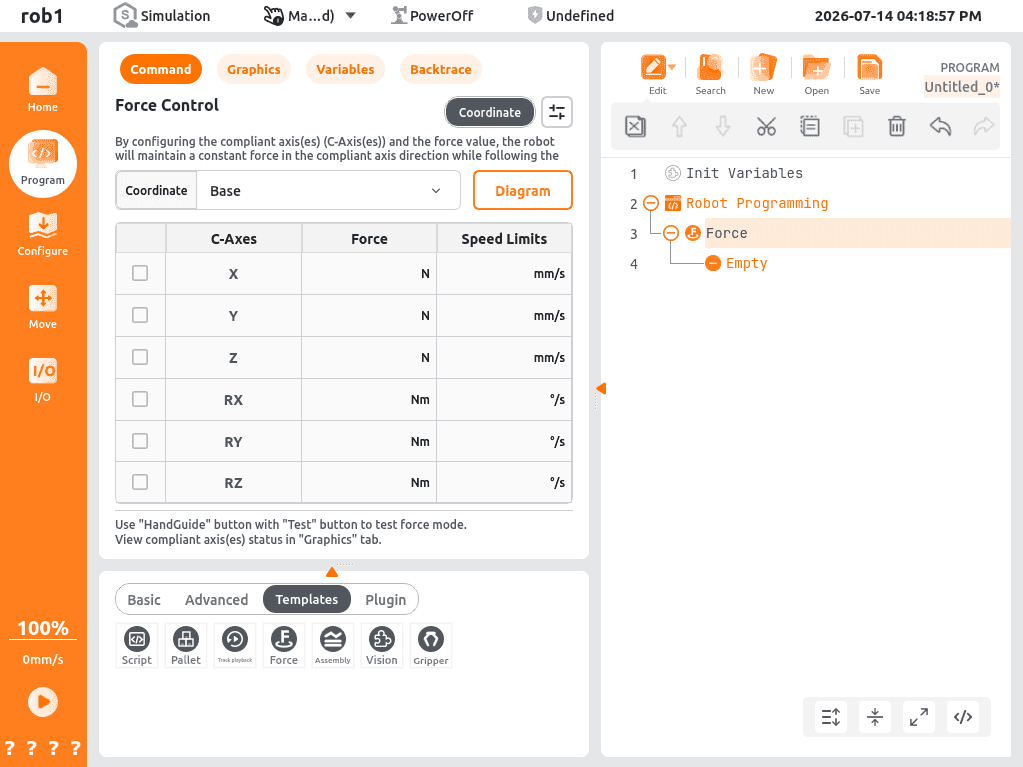
Control Mode: Coordinate System
Coordinate System Selection:
Base:
Description: A fixed coordinate system with its origin at the robot base. The coordinate system remains unchanged as the robot moves, and the constant-force direction remains fixed relative to the ground.
Suitable for tasks in which the force direction must remain perpendicular or parallel to the ground, such as surface grinding, vertical pressing, and loading/unloading.
Tool:
Description: A coordinate system with its origin at the end effector Tool Centre Point (TCP). It updates in real time as the tool pose changes. The constant-force direction is defined relative to the tool and follows its movement and rotation.
Typical applications: Suitable for tasks where the force direction must follow the tool pose, such as surface grinding and pin insertion.
Parameter Configuration:
After selecting the target C-Axes, configure the following parameters:
C-Axes: Select the axes (X/Y/Z/RX/RY/RZ) on which constant force control is to be enabled. Once selected, the corresponding axis enters compliant control mode.
Force: Specify the target force/torque to be maintained on each selected axis. The unit for linear axes is N, and the unit for rotational axes is Nm.
Linear axes: Data type:
float(2 decimal places), Range[0, sensor maximum range], If no sensor range is configured, the default upper limit is 2000 N. Default value: 0.Rotational axes: Data type:
float(2 decimal places), Range[0, sensor maximum range], If no sensor range is configured, the default upper limit is 100 Nm. Default value: 0.
Speed Limits: Specify the maximum motion speed for the selected axes to prevent unstable motion during constant force control.
Linear axes: Data type:
int, Unit: mm/s, Range:[1, end-effector speed limit], Default value: 150 mm/s.Rotational axes: Data type:
int, Unit: °/s, Range:[1, 360], Default value: 60 °/s.
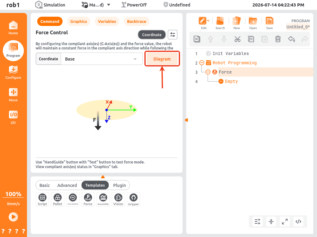
Once the configuration is complete, click [Diagram] to view it.
5.1.2 Force-Controlled Assembly
Force control enables high-precision assembly operations and supports multiple assembly modes through different child nodes, including force-controlled hole search and force-controlled compliant insertion/removal.
After configuring the desired assembly mode, stop conditions can be added. When a stop condition is triggered (e.g., timeout, force limit exceeded, or a logical condition evaluates to True), the current operation stops immediately, and program execution proceeds according to the configured logic. This helps protect the hardware and improve program logic.
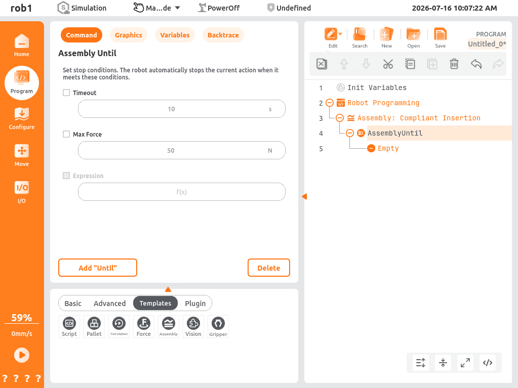
Timeout: Specifies the maximum execution time for the operation. Data type:
float(2 decimal places), Unit:s, Range:[1.00, 1000.00], Default: 5.00 (required).Maximum Force Limit: Specifies the maximum allowable contact force during the search. Data type:
float(2 decimal places), Unit: N , Range:[1.00, maximum sensor range], Default: 200.00.Expression: Defines a user-defined logical condition. When the expression evaluates to
True, the current operation stops immediately and program execution jumps to the next step.
5.1.2.1 Hole Search
Searches within a circular or rectangular region by following an increasingly dense trajectory along the workpiece surface while maintaining a constant contact force until the insertion depth reaches 5 mm.
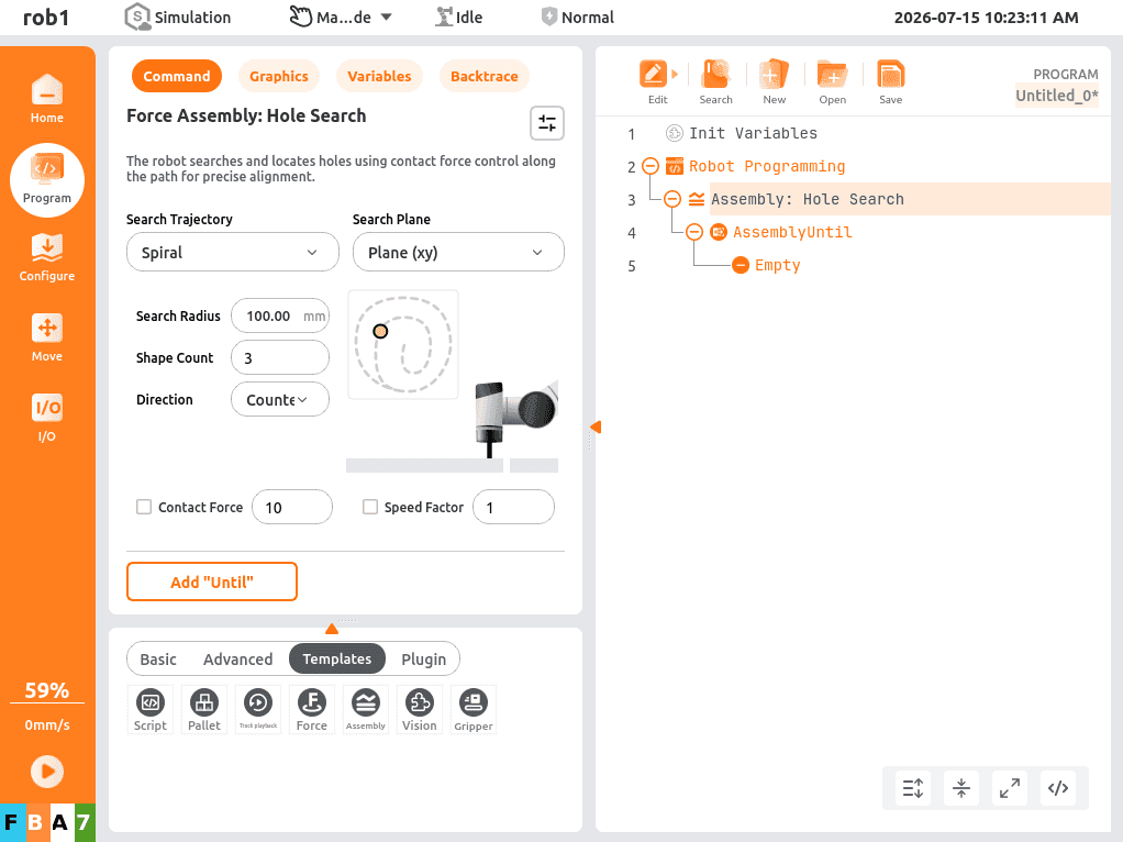
Search Trajectory
Spiral:
Search Radius: Specifies the radial extent of the spiral search path. Data type:
int, Unit: mm, Range:[1, 1000], Default: 10.Initial Density: Specifies the number of repetitions of the base search pattern at the start of the search. Range
[1,10], Default: 3.Direction: Specifies the rotation direction of the search path. Options: Clockwise or Counterclockwise.
Wave (Z):
Rectangle Length: Specifies the length of the rectangular search area for the zigzag search path. Data type:
int, Unit: mm, Range:[5, 1000], Default: 20.Initial Position: Specifies the initial angle of the zigzag search path. Range:
[-180, 180].Initial Density: Specifies the number of repetitions of the base search pattern at the start of the search. Range:
[1,10], Default: 3.
Search Plane: Defined relative to the coordinate system, where the
axis points horizontally to the right, the axis points horizontally forward, and the axis points vertically upward. Plane XY: The horizontal plane formed by the
and axes. Plane YZ: The plane formed by the
and axes. Plane XZ: The plane formed by the
and axes.
Auxiliary Parameters
Contact Force: Specifies the target contact force during the search operation. Data type:
float(2 decimal places), Unit: N , Range:[5.0, maximum measurement range], Default: 10.0.Note:
The maximum measurement range is determined using the sensor measurement range. If the sensor measurement range is unavailable, it shall be calculated using the following formula and rounded to the nearest integer:
Rated robot payload * 1.2 * 9.8 * 4.Speed Factor: Adjusts the speed scaling factor for the search motion. Data type:
float(1 decimal place), Range:[0.1, 5], Default: 1.0.
5.1.2.2 Compliant Insertion
Controls the robot to move along the predefined insertion/removal direction until the target position is reached.
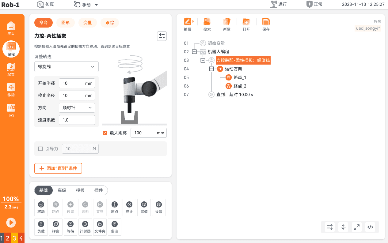
Trajectory Adjustment:
The trajectory adjustment module is used to define the motion compensation strategy during compliant insertion/removal. It supports three modes: Spiral, Side Swing, and Automatic Adaptation, and is intended to compensate for hole position deviation, misalignment, and jamming during assembly.
Automatic Adaptation
Insertion Speed: Specifies the axial insertion speed during compliant insertion. Data type:
int, Unit: mm/s, Range:[1, tool speed limit], Default: 10.Maximum Distance: Limits the maximum axial travel distance during adaptive insertion. Data type:
int, Unit: mm, Range:[1, 1000], Default: 100.Guiding Force: Specifies the guiding force applied during the automatic adaptation insertion process. Data type:
float(2 decimal places), Unit: N , Range:[0, maximum measurement range], Default: 0.
Spiral
Initial Radius: Specifies the initial radius of the spiral search path. Data type:
int, Unit: mm, Range:[1, 1000], Default 10.Final Radius: Specifies the final radius of the spiral search path. Data type:
int, Unit: mm, Range:[1, 1000], Default: 10.Direction: Specifies the rotation direction of the spiral search path during compliant insertion. Options: Clockwise or Counterclockwise.
Speed Factor: Adjusts the advancement speed of the spiral search path. Data type:
float(1 decimal place), Range:[0.1, 10.0], Default: 1.0.Maximum Distance: Specifies the maximum expansion distance of the spiral search path. Data type:
int, Unit: mm, Range:[1, 1000], Default: 100.Guiding Force: Specifies the guiding force applied during compliant insertion. Data type:
float(2 decimal places), Unit: N, Range: [0, maximum measurement range], Default: 0.
Side Swing
Maximum Distance: Specifies the maximum travel distance of the side-swing path. Data type:
int, Unit: mm, Range:[1, 1000], Default: 100.Guiding Force: Specifies the guiding force applied during the side-swing motion. Data type:
float(2 decimal places), Unit: N, Range:[0, maximum measurement range], Default: 0.Direction: Specifies the axis of the side-swing motion. Options:
RXorRY, Default:RX. This option is not available in alternating mode.Angle: Specifies the swing angle for the side-swing motion. Data type:
int, Unit: °, Range:[1, 30], Default: 5.Speed Factor: Adjusts the advancement speed of the side-swing motion. Data type:
float(1 decimal place), Range:[0.1, 10.0], Default: 1.0.
Motion Direction
Defines the fundamental motion parameters for compliant insertion, including the reference used to determine the motion direction, as well as the tool's motion speed and acceleration. These settings provide the fundamental motion configuration for the entire compliant process.
- Tool Center Point (TCP):
- Use Activated Tool Center Point: Uses the currently active TCP configured in the Teach Pendant as the motion reference point.
- Ignore Activated Tool Center Point: Ignores the currently active TCP and instead forcibly uses the robot flange center as the reference point for motion control.
- User-Defined Tool Center Point: Uses the user-created custom TCP as the dedicated reference point for compliant insertion, independent of the system's active TCP.
- Coordinate System:
- Base: global coordinate system that uses the robot base as the origin. All motion commands are interpreted in the base coordinate system, so the motion direction is not affected by the robot's pose.
- Tool: Local coordinate system that uses the currently active or user-defined TCP as the origin. The motion direction changes synchronically with the tool orientation.
- User-Defined Coordinate System: Uses a user-created custom coordinate system as the motion reference frame.
- Tool Speed: Defines the tool motion speed, Data type:
int, Unit: mm/s, Range:[1, maximum tool speed], Default: 10. - Tool Acceleration: Defines the tool motion acceleration, Data type:
float(2 decimal places), Unit: mm/s², Range:[0.01, maximum tool acceleration], Default: default value for the Linear Motion node.
- Tool Center Point (TCP):
5.2 Force Control Assembly Interfaces
5.2.1 Interface Overview
| Function Category | Interface Name | Description |
|---|---|---|
| Force Sensor | zeroTcpForce restoreTcpForce | Zeroes the force offset. Restores the force offset. |
| Compliant Grasping | fcGraspComp fcWaitGraspCompFinish | Grasps objects with uncertain positions. Waits for the grasp operation to complete. |
| Contact Detection | fcContact | Detects contact based on force threshold. |
| Alignment | fcAlign | Performs compliant alignment. |
| Hole Search | fcSearchHole | Searches for the hole position within the plane (using a meshing trajectory). |
| Hole Entry Check | fcCheckInHole | Determines whether the tool has entered the hole. |
| Compliant Insertion | fcInsertComp | Performs insertion under force-control constraints. |
5.2.2 Detailed Interface and Parameter Description
5.2.2.1 zeroTcpForce - Zero TCP Force Offset
Interface Definition
ret = zeroTcpForce(time)Description
Applies a moving-average filter to the six-axis force sensor at the end effector over the specified time period. The filtered result is then used as the force offset to zero the force readings.
Request Parameters
Parameter Type Required Unit Description Example timenumber Yes s Sampling duration, use averaging time window. Recommended: >= 0.5 s 1.0Return Values
Return Value Description AUBO_OK(0)Force offset zeroed successfully. FORCE_ZERO_FAILED(-104)Force offset zeroing failed (communication error/ sensor error/ or invalid parameter). Usage Constraints
Execute this function while the robot is stationary (with no external force applied to the end effector) to avoid errors caused by zeroing during motion.
During the zeroing process, ensure that the robot is not in contact with any external object.
5.2.2.2 restoreTcpForce - Force Offset Restoration
Interface Definition
ret = restoreTcpForce()Description
Restores the original force offset saved before zeroing. Typically used together with the TCP force offset zeroing interface after a force-control operation has been completed.
Return Values
Return Value Description AUBO_OK(0)Force offset restored successfully. FORCE_RESTORE_FAILED(-105)Force offset restoration failed (no data).
5.2.2.3 fcGraspComp - Compliant Grasping
Interface Definition
ret = fcGraspComp(params)Description
Used for grasping workpieces with uncertain positions. Grasp success is determined based on the force threshold along the compliant axis.
Request Parameters
Parameter Type Required Unit Value/Range Description Example featuretable[6] Optional — — Defines the grasp coordinate system (Base / Tool / User). Format: {x,y,z,rx,ry,rz}. Typically,{0,0,0,0,0,0}represents the base coordinate system. Use getTcpPose() to obtain the current pose and use it as the tool coordinate system.{0,0,0,0,0,0}soft_axistable[6] Yes — Either: 0/1 Specifies one or more C-Axes (indices in the feature coordinate system). For example, {1,0,0,0,0,0}indicates compliance along the X-axis.{1,1,0,0,0,0}soft_force_thresholdtable[6] Yes N >=0 Force threshold for each compliant axis. Grasping is considered successful when the force on an axis is below the corresponding threshold. {2,2,0,0,0,0}speed_limitnumber Optional m/s >0 Maximum speed along the compliant axis (TCP) 0.1max_distance_limitnumber Yes m >0 Maximum allowable displacement along the compliant axis 0.05grasp_timeoutnumber Optional s >0 Operation timeout 5.0Return Values
Return Value Description AUBO_OK(0)Compliant grasping mode entered successfully. AUBO_INVL_ARGUMENT(-5)Invalid parameter or initialization failed. Example
local fc = require('aubo.force_control')
params = {
  feature = {0,0,0,0,0,0},
  soft_axis = {1,0,0,0,0,0},
  soft_force_threshold = {2,2,0,0,0,0},
  speed_limit = 0.05,
  max_distance_limit = 0.02,
  grasp_timeout = 3.0
}
ret = fc.fcGraspComp(params)
5.2.2.4 fcWaitGraspCompFinish - Wait for Compliant Grasping to Complete
Interface Definition
ret = fcWaitGraspCompFinish(timeout)Description
Waits for
fcGraspCompto complete within the specified timeout period. Typically used together withfcGraspComp.Request Parameters
Parameter Type Required Unit Description Example timeoutnumber Yes s Maximum waiting time 5Return Values
Return Value Description AUBO_OK(0)Grasp operation completed successfully. AUBO_TIMEOUT(-4)Grasp operation not completed before the timeout expired. GRASPCOMP_DISTANCE_EXCEEDED(-451)Maximum distance limit exceeded.
5.2.2.5 fcContact - Contact Detection
Interface Definition
ret = fcContact(params)Description
Robot arm performs contact detection along the specified contact axis and stops immediately when the contact condition is satisfied.
Request Parameters
Parameter Type Required Unit Value/Range Description featuretable[6] Optional — — Defines the contact coordinate system. Format: {x,y,z,rx,ry,rz}compliancetable[6] Yes — Each axis: 0/1 Specifies the axes enabled for force control. For example, {0,0,1,0,0,0}enables force control only on the Z-axiswrenchtable[6] Yes N / Nm Target force/torque threshold Contact is detected when the measured force/torque reaches the threshold. For example, {0,0,10,0,0,0}env_stifftable[6] Optional — [0.0~1.0] Estimated environmental stiffness used by the force-control algorithm damp_scaletable[6] Optional — [0.1~1.0] Damping scaling factor stiff_scaletable[6] Optional — [0.0~1.0] Stiffness scaling factor speed_limitsnumber Optional m/s >0 Speed limit along the contact axis distancenumber Optional m >0 Maximum displacement limit. (Exceeding this returns a distance limit exceeded error) timeoutnumber Yes s >0 Operation timeout Return Values
Return Value Description AUBO_OK(0)Contact condition satisfied successfully. CONTACT_DISTANCE_EXCEEDED(-201)Maximum allowable distance exceeded (distance) AUBO_TIMEOUT(-4)Contact not detected before the timeout expired (timeout) Example
local fc = require('aubo.force_control')
params = {
  feature = {0,0,0,0,0,0},
  compliance = {0,0,1,0,0,0},
  wrench = {0,0,10,0,0,0},
  env_stiff = {0,0,0.8,0,0,0},
  damp_scale = {0.5,0.5,0.5,0.5,0.5,0.5},
  stiff_scale = {0.5,0.5,0.5,0.5,0.5,0.5},
  speed_limits = 0.02,
  distance = 0.1,
  timeout = 8
}
ret = fc.fcContact(params)
5.2.2.6 fcSearchHole - Hole Search
Interface Definition
ret = fcSearchHole(params)Description
Performs shaft–hole searching by following the specified search trajectory within the selected plane.
Request Parameters
Parameter Type Required Unit Value/Range Description search_planeSearchPlane Optional — xy(1)/xz(2)/yz(3) Search plane. Default: the XY plane of the TCP coordinate system search_rangenumber Yes m >0 Search radius or range search_timenumber Yes s >0 Maximum search duration guide_traj_typeGuideTrajType Optional — SPIRAL/MESHING/WEAVE Active guidance trajectory type. search_max_forcenumber Optional N >5 Maximum allowable force during the search process search_guide_forcenumber Optional N — Guiding force applied along the search direction speed_scalenumber Optional — [0.1~5] Global speed scaling factor search_damp_scaletable[6] Optional — [0.1~1] Damping adjustment search_stiff_scaletable[6] Optional — [0.1~1] Stiffness adjustment push_distancenumber Optional m >0 Feed distance Return Values
Return Value Description AUBO_OK(0)Search completed successfully. SEARCH_FORCE_EXCEEDED(-251)Force limit exceeded. The contact force during the search exceeded search_max_forceAUBO_TIMEOUT(-4)Search time out ( search_time)SEARCH_RANGE_EXCEEDED(-252)Search exceeded the search range Example
local fc = require('aubo.force_control')
params = {
  search_plane = SearchPlane.xy,
  search_range = 0.02,
  search_time = 15,
  guide_traj_type = GuideTrajType.WEAVE,
  search_max_force = 50,
  search_guide_force = 10,
  speed_scale = 1.0
}
ret = fc.fcSearchHole(params)
5.2.2.7 fcCheckInHole - Hole Entry Check
Interface Definition
inside = fcCheckInHole(params)Description
Performs compliant probing along the specified detection axis to determine whether the workpiece has entered the hole. Returns a Boolean value indicating the detection result.
Request Parameters
Parameter Type Required Unit Description check_axistable[3] Yes — Detection axis vector (tool coordinate system), e.g., {1,0,0}. Up to two directions are supportedcheck_rangenumber Yes m Detection displacement range check_forcenumber Yes N Force threshold along the search axis. Exceeding the threshold indicates that the workpiece has entered the hole check_speednumber Yes m/s Search speed (TCP) Return Values
Return Value Description trueThe workpiece has entered the hole. falseThe workpiece has not entered the hole (detection range exceeded or force threshold was not reached). Example
local fc = require('aubo.force_control')
params = {
  check_axis = {1,0,0},
  check_range = 0.02,
  check_force = 5.0,
  check_speed = 0.01
}
inside = fc.fcCheckInHole(params)
5.2.2.8 fcInsertComp - Compliant Insertion
Interface Definition
ret = fcInsertComp(params)Description
Robot performs insertion under compliant control. Supports multiple guidance trajectories (Spiral, Weave, and Linear), and terminates when the target insertion depth is reached or a fault occurs.
Request Parameters
Parameter Type Required Unit Description insert_selectInsertSelect Optional — Insertion direction relative to the tool coordinate system: x(1)/y(2)/z(3) (default z) insert_max_speednumber Optional m/s Maximum insertion speed. insert_timenumber Optional s Operation timeout guide_traj_typeGuideTrajType Optional — SPIRAL/WEAVE/LINE insert_max_forcenumber Optional N Maximum allowable force during insertion. insert_max_depthnumber Optional m Maximum insertion depth. insert_guide_forcenumber Optional N Guidance force speed_scalenumber Optional — Speed scaling factor [0.1~5] insert_damp_scaletable[6] Optional — Damping scaling factor [0.1~1] insert_stiff_scaletable[6] Optional — Stiffness scaling factor [0.0~1] Return Values
Return Value Description AUBO_OK(0)Insertion completed successfully (target depth reached or completion criteria satisfied). INSERT_FORCE_EXCEEDED(-351)Force limit exceeded ( insert_max_force)AUBO_TIMEOUT(-4)Operation timed out or the completion criteria were not satisfied. Example
local fc = require('aubo.force_control')
params = {
  insert_select = InsertSelect.z,
  insert_max_speed = 0.02,
  insert_time = 12,
  guide_traj_type = GuideTrajType.SPIRAL,
  insert_max_force = 20,
  insert_max_depth = 0.05,
  insert_guide_force = 2.0,
  speed_scale = 1.0
}
ret = fc.fcInsertComp(params)
5.2.2.9 fcAlign - Alignment
Interface Definition
ret = fcAlign(params)Description
Adjusts the position and orientation through compliant motion to achieve high-precision alignment between the target object and the contact surface.
Request Parameters
Parameter Type Required Unit Description align_axistable[6] Yes — Specifies the C-Axes in the tool coordinate system. Both translational and rotational axes can be enabled. For example, {0,0,0,1,1,0}enables alignment about the RX and RY axes.contact_axistable[3] Yes — Contact axis (principal axis of the tool coordinate system), e.g. {0,0,1}contact_forcenumber Yes N Target force along the contact axis, used for maintaining contact. align_speednumber Optional deg/s Maximum angular speed during alignment. max_limit_forcenumber Optional N Maximum allowable force during alignment. max_align_anglenumber Optional deg Maximum allowable alignment angle deviation judgment_levelnumber Optional — Judgement level [0.1~1.0] (Higher levels correspond to stricter alignment criteria). Return Values
Return Value Description AUBO_OK(0)Alignment successful ALIGN_ANGLE_EXCEEDED(-401)Alignment angle exceeded the maximum allowable range. ALIGN_FORCE_EXCEEDED(-402)Force limit exceeded Example
local fc = require('aubo.force_control')
params = {
  align_axis = {0,0,0,1,1,0},
  contact_axis = {0,0,1},
  contact_force = 10,
  align_speed = 0.02,
  max_limit_force = 30,
  max_align_angle = 10,
  judgment_level = 0.8
}
ret = fc.fcAlign(params)
5.2.3 Error Codes
5.2.3.1 Error Code Definitions
Error Code Reference:
FcErrorCode = {
    AUBO_OK = 0,

    -- General Errors (-1 ~ -99)
    AUBO_BAD_STATE              = -1,
    AUBO_QUEUE_FULL             = -2,
    AUBO_BUSY                   = -3,
    AUBO_TIMEOUT                = -4,
    AUBO_INVL_ARGUMENT          = -5,
    AUBO_NOT_IMPLETEMENT        = -6,
    AUBO_NO_ACCESS              = -7,
    AUBO_CONN_REFUSED           = -8,
    AUBO_CONN_RESET             = -9,
    AUBO_INPROGRESS             = -10,
    AUBO_EIO                    = -11,
    AUBO_NOBUFFS                = -12,
    AUBO_REQUEST_IGNORE         = -13,
    AUBO_ALGORITHM_PLAN_FAILED  = -14,
    AUBO_VERSION_INCOMPAT       = -15,
    AUBO_DIMENSION_ERR          = -16,
    AUBO_SINGULAR_ERR           = -17,
    AUBO_POS_BOUND_ERR          = -18,
    AUBO_INIT_POS_ERR           = -19,
    AUBO_ELP_SETTING_ERR        = -20,


    -- Force Control Module Errors (-100 ~ -199)
    FORCE_EXCEEDED          = -101,
    FORCE_CONTROL_INIT_FAIL = -102,
    FORCE_CONTROL_RUNTIME_ERR = -103,
    FORCE_ZERO_FAILED       = -104,
    FORCE_RESTORE_FAILED    = -105,

    -- Contact Module Errors (-200 ~ -249)
    CONTACT_DISTANCE_EXCEEDED  = -201,

    -- Hole Search Module Errors (-250 ~ -299)
    SEARCH_FORCE_EXCEEDED  = -251,
    SEARCH_RANGE_EXCEEDED          = -252,
    ENGAGEMENT_FAILED      = -254,

    -- Hole Entry Check Errors (-300 ~ -349)
    CHECK_NOT_IN_HOLE      = -301,
    CHECK_RANGE_EXCEEDED   = -302,

    -- Insertion Module Errors (-350 ~ -399)
    INSERT_FORCE_EXCEEDED  = -351,
    INSERT_DEPTH_EXCEEDED  = -352,

    -- Alignment Module Errors (-400 ~ -449)
    ALIGN_ANGLE_EXCEEDED   = -401,
    ALIGN_FORCE_EXCEEDED   = -402,

    -- Compliant Grasping Module Errors (-450 ~ -499)
    GRASPCOMP_DISTANCE_EXCEEDED  = -451,
}
Note:
All successful return values are unified as:
FcErrorCode.AUBO_OK (0).All failed return values use the error code ranges defined above.
Interfaces that return Boolean values (such as Hole Entry Check) continue to return
true/false.
5.2.3.2 Example Interface Error Codes
| Interface | Possible Return Values | Description |
|---|---|---|
| zeroTcpForce | FORCE_ZERO_FAILED | Force zeroing failed |
| fcContact | AUBO_TIMEOUT/ CONTACT_DISTANCE_EXCEEDED | Contact timeout / distance limit exceeded |
| fcSearchHole | SEARCH_FORCE_EXCEEDED / AUBO_TIMEOUT / SEARCH_RANGE_EXCEEDED | Force limit exceeded / time out / search range exceeded. |
| fcInsertComp | INSERT_FORCE_EXCEEDED / AUBO_TIMEOUT | Force limit exceeded / time out. |
| fcAlign | ALIGN_FORCE_EXCEEDED / ALIGN_ANGLE_EXCEEDED | Force limit exceeded / alignment angle limit exceeded. |
Note:
Verify that all parameters are valid (type and range) before each call.
If force limit is exceeded or an error is returned, immediately bring the robot to a safe stop. Perform an emergency stop if necessary, or switch to a safe trajectory.
For operations that may result in collisions (such as
fcContact,fcInsertComp), first perform a low-speed test run and record logs.
6 Force Control Application Examples
6.1 Touchscreen Function Test
Requirements Analysis
Functional Requirements: The robot arm holds a stylus and draws straight lines, circles, and other patterns on the touchscreen at a drawing speed of 50 mm/s.
Safety Requirements: The maximum contact force between the stylus and the touchscreen must not exceed 1.5 N to prevent damage to the screen.
Force Control Accuracy Requirements: While ensuring touchscreen safety during drawing, maintain the contact force between the stylus and the screen at 1 ± 0.5 N.
Note:
Touchscreen tilt angles may vary (typically between 30-60°).
Solution
Overall Approach: The robot arm holds a stylus and draws straight lines, circles, and other patterns on the touchscreen. Force control is used to maintain a contact force of 1 ± 0.5 N, between the stylus and the screen while maintaining a drawing speed of 50 mm/s.
Main Steps:
The robot arm moves from the initial position to a safe height above the touchscreen.
The robot arm approaches the touchscreen at a low speed. Once the stylus contacts the screen and the target force is reached, the drawing process begins.
The robot arm follows the predefined trajectory to draw straight lines, circles, or other patterns on touchscreen while maintaining a contact force of 1±0.5 N between the stylus and the screen.
After drawing is complete, the robot arm lifts the stylus and returns to the initial position.
Example Video for the Touchscreen Function Test:
Force Control Parameter Settings
Reference Coordinate System for Force Control: Set the coordinate system so that the x-y plane is parallel to the touchscreen and the Z-axis is perpendicular to the screen. The coordinate system origin may be defined arbitrarily. Either a moving or a fixed coordinate system may be used.
Force Control Direction: Enable force control along the Z-axis only. Disable force control on all other axes.
enable = {false, false, true, false, false, false}Target Force: Set the target force along the Z-axis to 2 N. Target forces for the other axes are ignored and are recommended to be set to 0.
goal_force = {0, 0.0, 2.0, 0.0, 0.0, 0.0}Reference Trajectory: During the drawing phase, use a user-defined straight-line or circular trajectory as reference. During the approach phase, the reference trajectory may be omitted and the robot can rely entirely on force-guided motion, or a reference trajectory (MoveL) may be specified to increase the approach speed.
Admittance Parameters:
M = {20, 20, 20, 10, 10, 10}
D = {0, 0, 300, 0, 0, 0}
K = {0, 0, 0, 0, 0, 0}
For related issues, refer to Force Control Applications FAQs.
6.2 Fabric Ironing
Requirements Analysis
Functional Requirements: The robot arm carries an iron and moves over the fabric surface along a predefined trajectory to perform fabric ironing.
Force Control Requirements: Maintain a contact force of 30 ± 5 N between the iron and the fabric to ensure effective ironing while preventing damage to the fabric.
Motion Speed Requirements: Maintain a robot motion speed of 100 mm/s throughout the ironing process to ensure uniform ironing.
Solution
Overall Approach: The robot manipulator carries an iron and follows a predefined trajectory over the fabric surface. Force control is used to maintain a contact force of 30 ± 5 N between the iron and the fabric while maintaining a travel speed of 100 mm/s.
Main Steps:
The robot arm moves from the initial position to a safe height above the fabric.
The robot arm approaches the fabric at a low speed. Once the iron contacts the fabric and the target force is reached, the ironing process begins.
The robot arm follows the predefined trajectory over the fabric surface while maintaining a contact force of 30±5 N between the iron and the fabric.
After ironing is complete, the robot arm lifts the iron and returns to the initial position.
Example Video for Fabric Ironing:
Force Control Parameter Settings
Reference Coordinate System for Force Control: Use either the actual TCP or the command TCP used for force control output.
Force Control Direction: Enable force control along the Z-axis only. Disable force control on all other axes.
enable = {false, false, true, false, false, false}Target Force: Set the target force along the Z-axis to 30 N. Target forces for the other axes are ignored and are recommended to be set to 0.
goal_force = {0, 0.0, 30, 0.0, 0.0, 0.0}Reference Trajectory: Use a user-defined straight-line or circular trajectory. Ensure that the trajectory remains parallel to the fabric surface.
Admittance Parameters:
M = {20, 20, 20, 10, 10, 10}
D = {0, 0, 2000, 0, 0, 0}
K = {0, 0, 0, 0, 0, 0}
For related issues, refer to Force Control Application FAQs.
6.3 Gear Meshing
Requirements Analysis
Functional Requirements: The robot arm carries the gear and performs precise meshing with a fixed gear.
Force Control Requirements: During gear meshing, maintain a contact force of 5 ± 1 N to prevent gear damage.
Accuracy Requirements: Achieve a gear meshing accuracy of 0.1 mm to ensure proper gear operation.
Solution
Overall Approach: The robot arm carries the gear and uses force control to achieve precise meshing with a fixed gear while maintaining a contact force of 5 ± 1 N throughout the meshing process and ensuring meshing accuracy.
Main Steps:
The robot arm moves from the initial position to a safe height above the fixed gear.
The robot arm approaches the fixed gear at a low speed. Once the gears make contact and the target force is reached, the meshing operation begins.
The robot arm uses force control to adjust its pose, enabling precise gear meshing.
After gear meshing is completed, the robot arm maintains its pose to complete the operation.
Example Video for Gear Meshing
Force Control Parameter Settings
Reference Coordinate System for Force Control: Use the TCP coordinate system, ensuring that its origin is located at the center of the gear.
Force Control Direction: Set the force control direction based on the gear meshing direction, typically along the X or Y axis.
Target Force: Set according to the gear size and material, typically 5 ± 1 N.
Reference Trajectory: Use a gear meshing trajectory and ensure that it is aligned with the tooth grooves of the fixed gear.
Admittance Parameters:
M = {20, 20, 20, 10, 10, 10}
D = {0, 0, 1000, 0, 0, 0}
K = {0, 0, 0, 0, 0, 0}
enable = {false, false, true, false, false, false}
goal_force = {0, 0.0, 5, 0.0, 0.0, 0.0}
Admittance Parameters (adjusted):
M = {20, 20, 20, 10, 10, 10}
D = {0, 0, 2000, 0, 0, 0}
K = {0, 0, 0, 0, 0, 0}
enable = {false, false, true, false, false, false}
goal_force = {0, 0.0, 8, 0.0, 0.0, 0.0}
Admittance Parameters (final):
M = {20, 20, 20, 10, 10, 10}
D = {2000, 2000, 2000, 1000, 1000, 1000}
K = {0, 0, 0, 0, 0, 0}
enable = {true, true, true, true, true, false}
goal_force = {0, 0.0, 20, 0.0, 0.0, 0.0}
6.4 Automatic USB Drive Insertion/Removal
Requirements Analysis
Functional Requirements: The robot arm holds a USB drive and automatically inserts it into and removes it from a computer USB port.
Force Control Requirements: Maintain a contact force of 10 ± 2 N during the insertion and removal process to prevent damage to the USB port.
Accuracy Requirements: Achieve a USB port alignment accuracy of 0.5 mm to ensure proper USB insertion.
Solution
Overall Approach: The robot arm holds a USB drive and uses force control to automatically insert it into and remove it from a computer USB port while maintaining a contact force of 10 ± 2 N throughout the operation and ensuring alignment accuracy.
Main Steps:
The robot arm moves from the initial position to a safe position in front of the computer USB port.
The robot arm approaches the USB port at a low speed. Once the USB drive contacts the port and the target force is reached, insertion begins.
The robot arm uses force control to adjust its pose and achieve precise USB insertion.
After insertion, the robot arm maintains its pose to complete the USB insertion operation.
During removal, the robot arm withdraws the USB drive at a low speed while maintaining a contact force of 10 ± 2 N.
Example Video of Automatic USB Drive Insertion/Removal:
Force Control Parameter Settings:
Reference Coordinate System for Force Control: Use the TCP coordinate system, ensuring that its origin is located at the center of the USB drive.
Force Control Direction:
Guide Slot Entry Stage: Use the guide slot to correct the USB drive's Rx and Ry orientation.
Insertion Stage: Enable force control in the X,Y, and Z directions. Practical validation has shown that, due to physical tolerances of the USB connector, rotating the USB connector downward and applying a negative force in the Rx direction helps achieve full insertion.
Target Force:
Guide Slot Entry Stage: Set the target force to 1 N on the TCP-Z axis. It is recommended to set the target force for all other axes to 0.
Insertion Stage: Set the target force to 0.5 N along the Rx direction. It is recommended to set the target force for all other axes to 0.
Admittance Parameters:
Admittance Parameters (Guide Slot Entry Stage):
M = {20, 20, 20, 10, 10, 10}
D = {0, 0, 1000, 1000, 1000, 0}
K = {0, 0, 0, 0, 0, 0}
Admittance Parameters (Insertion Stage):
M = {20, 20, 20, 10, 10, 10}
D = {1000, 1000, 1500, 1500, 0, 0}
K = {0, 0, 0, 0, 0, 0}
6.5 Waterproof Cover Installation
Requirements Analysis
Functional Requirement: The robot holds the waterproof cover and performs precise installation onto the device.
Force Requirement: Maintain a contact force of 8 ± 2 N during installation to prevent damage to the waterproof cover.
Accuracy Requirement: Achieve an installation accuracy of 0.2 mm to ensure proper sealing performance.
Solution
Overall Approach: The robot arm holds the waterproof cover and uses force control to install it precisely onto the device while maintaining a contact force of 8 ± 2 N throughout the installation process and ensuring installation accuracy.
Main Steps:
The robot arm moves from the initial position to a safe height above the device.
The robot arm approaches the device at a low speed. Once the waterproof cover contacts the device and the target force is reached, installation begins.
The robot arm uses force control to adjust its pose and achieve precise installation of the waterproof cover.
After the waterproof cover has been installed, the robot arm maintains its pose to complete the operation.
Example Video for Waterproof Cover Installation:
Force Control Parameter Settings
Reference Coordinate System for Force Control: Use the TCP coordinate system, ensuring that its origin is located at the center of the waterproof cover.
Force Control Direction:
Approach Stage: Enable force control on the TCP X and Y axes only. Disable force control on all other axes.
Pressing Stage: Enable force control on the TCP-X, TCP-Y and TCP-Z axes only. Disable force control on all other axes.
Target Force:
Approach Stage: Set the target force to 2 N on the TCP-X and TCP-Y axes. Target force settings for all other axes are ignored; it is recommended to set them to 0.
Pressing Stage: Set the target force to 0 N on the TCP-X and TCP-Y axes, and 5 N on the TCP Z axis. Target force settings for all other axes are ignored; it is recommended to set them to 0.
Admittance Parameters:
Admittance Parameters (Approach Stage):
M = {20, 20, 20, 10, 10, 10}
D = {500, 500, 0, 0, 0, 0}
K = {0, 0, 0, 0, 0, 0}
Admittance Parameters (Pressing Stage):
M = {20, 20, 20, 10, 10, 10}
D = {500, 500, 800, 0, 0, 0}
K = {0, 0, 0, 0, 0, 0}
6.6 Knob Installation
Requirements Analysis
Functional Requirements: The robot arm holds the knob and performs precise installation onto the device.
Force Control Requirements: Maintain a force of 10 ± 2 N during installation to prevent damage to the knob.
Accuracy Requirements: Achieve an installation accuracy of 0.1 mm to ensure proper knob operation.
Solution
Overall Approach: The robot arm holds the knob and uses force control to achieve precise installation onto the device while maintaining a force of 10 ± 2 N throughout the installation process and ensuring installation accuracy.
Main Steps:
The robot arm moves from the initial position to a safe height above the device.
The robot arm approaches the device at a low speed. Once the knob contacts the device and the target force is reached, installation begins.
The robot arm uses force control to adjust its pose and achieve precise knob installation.
After installation, the robot arm maintains its pose to complete the knob installation.
Example Video for Knob Installation:
Force Control Parameter Settings
Reference Coordinate System for Force Control: Use the TCP coordinate system, ensuring that its origin is located at the center of the knob.
Force Control Direction:
Outer Ring Alignment Hole Search: Enable force control on the TCP-Z axis only. Disable force control on all other axes.
Inner Shaft Alignment Hole Search: Enable force control on the TCP-Z axis only. Disable force control on all other axes.
Target Force:
Outer Ring Alignment Hole Search: Set the target force to 8 N along the TCP-Z axis. All other axes are ignored; it is recommended to set them to 0.
Inner Shaft Alignment Hole Search: Set the target force to 5 N along the TCP-Z axis. All other axes are ignored; it is recommended to set them to 0.
Admittance Parameters:
Admittance Parameters (Outer Ring Alignment):
M = {20, 20, 20, 10, 10, 10}
D = {500, 500, 0, 0, 0, 0}
K = {0, 0, 0, 0, 0, 0}
Admittance Parameters (Inner Shaft Alignment):
M = {20, 20, 20, 10, 10, 10}
D = {500, 500, 800, 0, 0, 0}
K = {0, 0, 0, 0, 0, 0}
6.7 Hinge Installation
Requirements Analysis
Functional Requirements: The robot arm holds the hinge and performs precise installation onto the device.
Force Control Requirements: Maintain a force of 8 ± 2 N during installation to prevent damage to the hinge.
Accuracy Requirements: Achieve an installation accuracy of 0.1 mm to ensure proper hinge operation.
Solution
Overall Approach: The robot arm holds the hinge and uses force control to achieve precise installation onto the device while maintaining a force of 8 ± 2 N throughout the installation process and ensuring installation accuracy.
Main Steps:
The robot arm moves from the initial position to a safe height above the device.
The robot arm approaches the device at a low speed. Once the hinge contacts the device and the target force is reached, installation begins.
The robot arm uses force control to adjust its pose and achieve precise hinge installation.
After installation, the robot arm maintains its pose to complete the hinge installation.
Example Video for Hinge Installation
Force Control Parameter Settings
Reference Coordinate System for Force Control: Use the TCP coordinate system, ensuring that its origin is located at the center of the hinge.
Force Control Direction:
- Hinge Rotation: Enable force control on the TCP-Z axis only. Disable force control on all other axes.
Hinge Pressing: Enable force control on the TCP-Z axis only. Disable force control on all other axes.
Target Force:
Hinge Rotation: Set the target force to 8 N along the TCP-Z axis. All other axes are ignored; it is recommended to set them to 0.
Hinge Pressing: Set the target force to 5 N along the TCP-Z axis. All other axes are ignored; it is recommended to set them to 0.
Admittance Parameters
Admittance Parameters (Hinge Rotation):
M = {20, 20, 20, 10, 10, 10}
D = {0, 0, 1000, 0, 0, 0}
K = {0, 0, 0, 0, 0, 0}
Admittance Parameters (Hinge Pressing):
M = {20, 20, 20, 10, 10, 10}
D = {0, 0, 1000, 0, 0, 0}
K = {0, 0, 0, 0, 0, 0}
6.8 Driver Board Installation
Requirements Analysis
Functional Requirements: The robot arm holds the driver board and performs precise installation onto the device.
Force Control Requirements: Maintain a force of 5 ± 1 N during installation to prevent damage to the driver board.
Accuracy Requirements: Achieve an installation accuracy of 0.1 mm to ensure proper operation of the driver board.
Solution
Overall Approach: The robot arm holds the driver board and uses force control to achieve precise installation onto the device while maintaining a contact force of 5 ± 1 N throughout the installation process and ensuring installation accuracy.
Main Steps:
The robot arm moves from the initial position to a safe height above the device.
The robot arm approaches the device at a low speed. Once the driver board contacts the device and the target force is reached, installation begins.
The robot arm uses force control to adjust its pose and achieve precise driver board installation.
After installation, the robot arm maintains its pose to complete the driver board installation.
Example Video for Driver Board Installation:
Force Control Parameter Settings:
Reference Coordinate System for Force Control: Use the TCP coordinate system, ensuring that its origin is located at the center of the driver board.
Force Control Direction:
Position Verification: Enable force control on the TCP-X axis and the Rz axis only. Disable force control on all other axes.
Pressing: Enable force control on the TCP-Z axis only. Disable force control on all other axes.
Slot Insertion: Enable force control on the TCP-X axis only. Disable force control on all other axes.
Target Force:
Position Verification: Set the target force to 2 N along the TCP-X axis. All other axes are ignored; it is recommended to set them to 0.
Pressing: Set the target force to 5 N along the TCP-Z axis. All other axes are ignored; it is recommended to set them to 0.
Slot Insertion: Set the target force to 8 N along the TCP-X axis. All other axes are ignored; it is recommended to set them to 0.
Admittance Parameters
Admittance Parameters (Position Verification):
M = {20, 20, 20, 10, 10, 10}
D = {1000, 0, 0, 0, 0, 500}
K = {0, 0, 0, 0, 0, 0}
Admittance Parameters (Pressing):
M = {20, 20, 20, 10, 10, 10}
D = {0, 0, 1000, 0, 0, 0}
K = {0, 0, 0, 0, 0, 0}
Admittance Parameters (Slot Insertion):
M = {20, 20, 20, 10, 10, 10}
D = {1000, 0, 0, 0, 0, 0}
K = {0, 0, 0, 0, 0, 0}
6.9 Multi-Stage Force Control
Requirements Analysis
Functional Requirements: The robot arm performs multi-stage force control to accommodate different operational requirements.
Force Control Requirements: Maintain the force at its setpoint during each stage, with a force error not exceeding 0.5 N.
Accuracy Requirements: Ensure that switching between force control stages is completed within 0.1 s to provide smooth operation.
Solution
Overall Approach: The robot arm uses multi-stage force control to implement force control during different stages of operation, ensuring that the force at each stage is maintained at its setpoint while enabling smooth transitions between force control stages.
Main Steps:
The robot arm moves from the initial position to the operating position.
The robot arm executes each operation stage sequentially according to the predefined multi-stage force control parameters.
After each stage is completed, the robot arm automatically switches to the next set of force control parameters.
After all stages are completed, the robot arm returns to the initial position.
Example Video of Multi-Stage Force Control:
Force Control Parameter Settings
Reference Coordinate System for Force Control: Use the TCP coordinate system, ensuring that its origin is located at the center of the operating tool.
Force Control Direction: Enable force control on the TCP-Z axis only. Disable force control on all other axes.
enable = {false, false, true, false, false, false}Target Force:
Stage 1: Set the target force to 6 N along the TCP-Z axis.
Stage 2: Set the target force to 1 N along the TCP-Z axis.
Stage 3: Set the target force to 6 N along the TCP-Z axis.
Reference Trajectory: Use a multi-stage trajectory defined according to the operational requirements. Ensure that the trajectory remains parallel to the operating surface.
Admittance Parameters:
M = {20, 20, 20, 10, 10, 10}
D = {0, 0, 1000, 0, 0, 0}
K = {0, 0, 0, 0, 0, 0}
6.10 Charging Port Insertion/Removal
Requirements Analysis
Functional Requirements: The robot arm holds the charging connector and performs automatic insertion and removal from the device's charging port.
Force Control Requirements: Maintain a contact force of 15 ± 3 N during insertion and removal to prevent damage to the charging port.
Accuracy Requirements: Achieve an alignment accuracy of 0.5 mm for the charging port to ensure normal charging operation.
Solution
Overall Approach: The robot arm holds the charging connector and uses force control to perform automatic insertion and removal from the device's charging port while maintaining a force of 15 ± 3 N throughout the operation and ensuring alignment accuracy.
Main Steps:
The robot arm moves from the initial position to a safe position in front of the device's charging port.
The robot arm approaches the charging port at a low speed. Once the connector contacts the port and the target force is reached, insertion begins.
The robot arm uses force control to adjust its pose and achieve precise insertion of the charging connector.
After insertion, the robot arm maintains its pose to complete the insertion operation.
During removal, the robot arm withdraws the charging connector at a low speed while maintaining a force of 15 ± 3 N.
Example Video of Charging Port Insertion/Removal:
Force Control Parameter Settings
Reference Coordinate System for Force Control: Use the TCP coordinate system, ensuring that its origin is located at the center of the charging connector.
Force Control Direction:
Hole Search: Enable force control on the TCP-Z axis only. Disable force control on all other axes.
Insertion/Removal: Enable force control on all axes except Rz.
Target Force:
Hole Search: Set the target force to 40 N along the TCP-Z axis.
Insertion/Removal: Set the target force for each axis according to the application requirements.
Admittance Parameters:
Admittance Parameters (Hole Search):
M = {20, 20, 20, 10, 10, 10}
D = {1000.0, 1000.0, 2500.0, 100.0, 100.0, 50}
K = {6000.0, 6000.0, 1000.0, 0.0, 0.0, 0.0}
Admittance Parameters (Insertion/Removal):
M = {20, 20, 20, 10, 10, 10}
D = {600.0, 600.0, 3500.0, 200.0, 200.0, 200.0}
K = {10.0, 10.0, 4000.0, 200.0, 200.0, 200.0}
For related issues, refer to Force Control Application FAQs.
7 Frequently Asked Questions
7.1 Force Sensor
Issue: How should sensor activation failure be handled?
Cause:
The sensor hardware connection is loose (e.g., poor RS-485 connection or disconnected power cable).
Incorrect sensor brand or model selected (the controller configuration does not match the actual sensor).
The installed ARCS version is outdated and does not support the current sensor driver.
The sensor driver plug-in has not been properly installed.
Solution:
Check the physical sensor connections. Reconnect the RS-485 interface/power cable, and ensure all connections are secure.
Verify the controller configuration: Navigate to "Configuration > General > Tool I/O > Tool RS-485", and ensure that the configured sensor brand and model match the actual sensor.
Upgrade the ARCS system to version
v0.31.1or later.For external sensors, redeploy the sensor driver plug-in: refer to Section 4.3.3 to rerun the plug-in installation script and verify that the configuration in
/root/arcs_ws/config/aubo_control.confis correct.
Issue: How should large sensor zero-point calibration errors be corrected (or how can calibration accuracy be improved)?
Cause:
External forces interfered with the robot arm during calibration (e.g., collisions or unintended contact).
An incorrect calibration orientation is selected (the positive direction of each TCP axis does not face downward as required).
The payload parameters are incorrectly configured (TCP offset or incorrect payload mass settings).
Sensor drift has occurred (periodic calibration has not been performed).
Solution:
Before calibration, ensure that the robot arm is free from external forces and that the surrounding area is clear of obstacles.
Follow the requirements strictly when defining the calibration poses: Ensure that the positive X/Y/Z axes of the TCP each point downward, with no overlap or interference between the three poses.
Reconfigure the payload parameters: Navigate to "Configuration > Plug-ins > Force Control > Calibration". Then verify the offset, payload mass, and center-of-mass data to ensure they match the actual payload.
Calibrate the sensor periodically: Perform factory-standard sensor calibration every three months to minimize sensor drift.
7.2 Force Control Plug-in Installation
Issue: Plug-in version compatibility issues.
Cause:
The force control plug-in version is incompatible with the ARCS system version (e.g., Installing an older plug-in on a newer ARCS version).
The sensor plug-in version conflicts with the force control plug-in version.
Solution:
Contact AUBO technical support to obtain a force control plug-in version compatible with your current ARCS version.
Uninstall the existing plug-in before deploying a new version. Run
sh uninstall.sh, then install the new version.Ensure that the sensor plug-in and force control plug-in versions are synchronized (e.g., Kunwei Sensor Plug-in v1.1, Force Control Plug-in v1.2).
Issue: The force control plug-in does not appear on the teach pendant after installation.
Cause:
The plug-in has not been enabled (the teach pendant was not restarted after installation).
The plug-in installation path is incorrect (the package was not extracted to the
/root/arcs_ws/extensions/directory).The teach pendant cache has not been cleared (the old configuration is overriding the new plug-in).
Solution:
Go to "Settings > System > Plug-ins", enable the force control plug-in, then click [Restart] to apply the changes.
Verify the plug-in installation path. Ensure that
force_control.sois located in the/root/arcs_ws/extensions/force_control/directory.Clear the teach pendant cache: Run
rm -rf /root/arcs_ws/cache/*, then restart the teach pendant.
Issue: Communication failure, sensor disconnected, or data is not updating.
Cause:
The 24 V power supply is disconnected or abnormal.
The RS-485 A/B wiring is reversed.
The communication cable is disconnected or damaged.
Solution:
Check the 24 V power indicator (if available), or measure the voltage between V+ and GND.
Swap the A and B wires and test again.
Check that the wiring terminals are secure and the communication cable is intact.
Issue: Sensor data drift exceeds the normal range, or the zero point is unstable.
Cause:
Large ambient temperature fluctuations or insufficient sensor warm-up.
Installation stress is present, or the sensor is not mounted perpendicular to the mounting surface.
The sensor zero-point calibration has not been performed.
Solution:
Place the sensor in a thermally stable environment and allow it to run for 30 minutes before re-evaluating data stability.
Reinstall the sensor, ensure coaxial alignment, and eliminate installation stress.
Perform sensor zero-point calibration via "Configuration > General > Tool I/O".
Issue: The force control function cannot be enabled (ARCS system).
Cause:
The installed ARCS version is too old and does not provide native support for force control.
The sensor model is not officially supported.
Solution:
Upgrade the ARCS system to v0.31.1 or later versions.
Verify that the sensor model is included in the official supported device list. Replace it with a supported model if necessary.
7.3 Force Control Parameter Optimization
Issue: Excessive force overshoot (target force: 10 N; peak force: 12 N+).
Cause:
The damping coefficient (
) is too low (insufficient motion resistance at the end effector, causing inertial force overshoot). The target force is too high/the approach speed is too fast (the inertia of the robot arm cannot be compensated in time).
The mass coefficient (
) is too high (excessive end-effector inertia resulting in a delayed force response).
Solution:
Increase the damping coefficient (
): incrementally by 10% each adjustment, until force overshoot ≤ 10% (e.g., increase the Z-axis from 1000 to 1200). Reduce the approach speed: Keep the speed during force-controlled motion ≤ 50 mm/s to avoid inertial impact.
Reduce the mass coefficient (
) appropriately: Decrease it by 10% each adjustment to improve the force response speed (e.g., reduce from 20 to 18). Apply the target force in stages: Initially set the target force to 70% of the required value, then increase it to the target value after stable contact (e.g., first apply 7 N, then increase to 10 N once the force has stabilized).
Issue: Excessive force fluctuation (greater than ±0.5 N).
Cause:
The mass coefficient (
) is too low (insufficient end-effector inertia, making the system susceptible to environmental disturbances). An incorrect coordinate system is selected (the TCP coordinate system is not used, resulting in force calculation errors).
Environmental vibration (e.g., the workbench is not securely fixed).
Solution:
Increase the mass coefficient (
): incrementally by 10% each adjustment until the force fluctuation is reduced to ≤ ±0.2 N. Set the force-control reference coordinate system to the TCP coordinate system (to ensure that force calculations are based on the end effector tool).
Secure the workbench and add vibration-damping pads to minimize disturbances due to environmental vibration.
7.4 Force Control Application
Issue: Excessive force during the approach stage of the touchscreen function test.
Cause: The approach speed is too high, and the inertia of the robot manipulator causes the force to exceed the safety threshold.
Solution: Reduce the approach speed, configure an appropriate approach trajectory, and use force-guided motion during the approach.
Issue: Excessive force fluctuation during drawing in the touchscreen function test.
Cause: The admittance parameters are not properly configured, and the robot arm stiffness is too high.
Solution: Adjust the admittance parameters, increase the damping coefficient, and reduce the stiffness coefficient.
Issue: Unstable force control caused by changes in the touchscreen angle during the touchscreen function test.
Cause: The coordinate system orientation does not match the actual orientation of the touchscreen.
Solution: Use the vision system to detect the touchscreen angle in real time and dynamically adjust the coordinate system orientation.
Issue: How should different fabric thicknesses requiring different target forces during fabric ironing be handled?
Solution: Adjust the target force according to the fabric thickness, and use the vision system to detect the fabric thickness.
Issue: Difficulty aligning the charging connector during insertion and removal.
Cause: The charging connector requires high positioning accuracy, while the robot manipulator positioning error is relatively large.
Solution: Use the vision system for assisted positioning to improve the positioning accuracy of the robot arm.
Issue: Excessive insertion force during charging connector insertion and removal.
Cause: The inertia of the robot arm causes the force to exceed the safety threshold.
Solution: Reduce the insertion speed and configure appropriate force control parameters.
Issue: What causes connector damage during charging connector insertion and removal?
Cause: Excessive force during insertion and removal, or an incorrect tool orientation.
Solution: Optimize the force-control parameters to ensure that the insertion and removal force remains within the safe operating range.
8 Summary and General Precautions
8.1 Core Summary
The core of force control is closed-loop force–position regulation. First adjust the damping coefficient (
) to reduce force overshoot, then adjust the mass coefficient ( ) to improve response speed. It is recommended to set the stiffness coefficient ( ) of the force-controlled axis to 0. Accurate force control depends on proper force sensor calibration and TCP calibration. Both must be performed in accordance with the specified procedures to prevent force control failures caused by incorrect system configuration.
The key differences between force control applications lie in the combination of the "force control direction, target force, and admittance parameters". These parameters should be configured according to the characteristics of the application (For example, constant-force operations typically enable force control only along the Z-axis, whereas alignment operations often require multi-axis force control).
8.2 General Precautions
Safety: Before starting force control operations, establish a safe operating area and configure force-limit emergency stop thresholds to prevent injury to personnel or damage to equipment.
Parameter Tuning: Follow the tuning sequence of "Damping (D) → Mass (M) → Stiffness (K)". Adjust only one parameter at a time to simplify troubleshooting and avoid interactions between multiple parameter changes.
Routine Maintenance: Recalibrate the force sensor to zero every three months, and verify plug-in compatibility with the ARCS system every six months to ensure long-term operation.