
AUBO Robot Equipment Maintenance and Hardware Service Manual
1 About This Manual
1.1 Version Information
| Item | Content |
|---|---|
| Manual name | AUBO Robot Equipment Maintenance and Hardware Service Manual |
| Manual version | v1.0.0 |
| Release date | 2026-09-07 |
| Applicable products | AUBO robot arms, AUBO controllers |
The AUBO Robot Equipment Maintenance and Hardware Service Manual (hereinafter referred to as "this Service Manual") is revised from time to time to reflect product iterations, field service experience, and changes in applicable standards. Revisions may be made without prior notice. Always refer to the latest version published by AUBO.
1.2 Copyright and Disclaimer
This manual is the proprietary material of AUBO (Beijing) Intelligent Technology Co., Ltd. No organization or individual may reproduce, duplicate, translate, adapt, reprint, excerpt, publish, or otherwise use all or part of this manual in any form without the prior written permission of AUBO (Beijing) Intelligent Technology Co., Ltd.
AUBO (Beijing) Intelligent Technology Co., Ltd. continuously improves the reliability, functions, and performance of its products and reserves the right to upgrade products without prior notice. Every effort has been made to ensure that the contents of this manual are accurate and complete; however, AUBO (Beijing) Intelligent Technology Co., Ltd. accepts no liability for errors or omissions arising from typesetting, description, or delayed information updates.
AUBO (Beijing) Intelligent Technology Co., Ltd. shall not be liable for equipment damage, personal injury, production loss, or any other direct or indirect loss resulting from installation, use, maintenance, or repair performed in a manner that does not comply with this manual, the product nameplate, site safety regulations, or applicable laws and regulations.
Copyright © 2015-2026 AUBO. All rights reserved.
1.3 Purpose of This Manual
This manual is intended to guide users, integrators, and authorized service personnel in performing routine maintenance, hardware servicing, basic inspections, and troubleshooting on AUBO robotic equipment, provided that all applicable safety requirements are met.
Read this manual and the associated product documentation in full before installing, operating, or servicing the product. Keep them in a safe place so that they are readily available for consultation and reference.
The illustrations, graphical user interfaces, and component appearances shown in this manual are for explanatory purposes only and may differ from the actual product configuration. Always refer to the delivered hardware and the documentation provided for the corresponding model.
This manual cannot cover every field application, system integration form, or abnormal operating condition. Any operation not explicitly described in this manual as permissible shall be regarded as prohibited for the user to perform independently. If such an operation becomes necessary, consult AUBO Technical Support or an AUBO-authorized service organization first, and proceed only in accordance with the solution they confirm.
1.4 Intended Audience
This manual is intended for the following personnel:
- Trained equipment maintenance and repair personnel;
- Robot system integrators and on-site commissioning personnel;
- Safety management personnel;
- Personnel responsible for equipment operation, routine inspection, and maintenance management.
1.5 Prerequisites
Personnel reading and using this manual shall meet the following requirements:
- Have received the relevant training provided by AUBO (or an AUBO-authorized distributor);
- Possess the fundamental knowledge required for the installation and maintenance of mechanical, electrical, and automation equipment;
- Be familiar with the robot work cell, end-of-arm tooling, peripheral equipment, and site safety management requirements;
- Be capable of hazard identification, power isolation, prevention of unintended start-up, use of personal protective equipment, and safe operating practices;
- Have read and understood the safety instructions in this manual and in the associated documentation.
Except for the inspection, cleaning, and servicing items explicitly permitted in this manual, the user shall not disassemble, repair, adjust, or modify the mechanical system, electrical system, controller, teach pendant, or accessories of the robot. Any unauthorized operation may result in equipment damage, personal injury, or voiding of the warranty. Work involving repair, component replacement, troubleshooting, and verification of safety functions shall be performed by personnel trained by AUBO or an AUBO-authorized service organization.
Before performing maintenance or repair, stop the robot program, bring the robot to a safe state, and disconnect the controller mains supply as well as the energy supply to all related external equipment. Where necessary, take measures to prevent unintended energization, unintended start-up, and accidental release of stored energy. Work may begin only after it has been confirmed that no additional hazards are present, such as unintended movement of end-of-arm tooling, fixtures, clamps, peripheral equipment, or workpieces.
1.6 Related Documentation
When using this manual, also consult the robot arm user manual, the controller user manual, the ARCS software manual, and the relevant application documents for the corresponding model. In the event of any discrepancy between documents, the official documentation for the corresponding product and software version shall prevail.
1.7 Obtaining Additional Information
If a product fails, contact an AUBO-authorized distributor or the AUBO after-sales service team. If parts need to be replaced, order new parts through an AUBO-authorized distributor or the AUBO after-sales service team. AUBO assumes warranty responsibility only for products and parts sold through authorized channels and covered by the warranty terms.
To obtain product documentation, service support, training information, or the latest version of this manual, visit https://www.aubo-robotics.cn, or contact the AUBO after-sales service team or an authorized distributor.
2 Safety
2.1 Safety Symbols
This manual uses the safety symbols listed below to identify important safety information. Whenever one of these symbols appears, read and comply with the corresponding instructions.
| Symbol | Level | Description |
|---|---|---|
 | DANGER | Indicates a hazardous situation which, if not avoided, will result in death or serious injury. |
 | WARNING | Indicates a hazardous electrical situation which, if not avoided, could result in personal injury or serious equipment damage. |
 | CAUTION | Indicates a hazardous situation which, if not avoided, could result in minor personal injury or equipment damage. Depending on the circumstances, an item marked with this symbol may lead to serious consequences. |
 | NOTICE | Indicates a situation which, if not avoided, could result in personal injury or equipment damage. Depending on the circumstances, an item marked with this symbol may lead to serious consequences. |
2.2 Safety Instructions
| Symbol | Instruction |
|---|---|
| 1. Ensure that all equipment which must not come into contact with water is kept dry. If water has entered the product, disconnect the power supply and then contact your supplier. 2. Use only the original cables supplied with the robot. Do not use the robot in applications that require the cables to be bent repeatedly. If longer cables or flexible cables are required, contact your supplier. 3. All GND terminals mentioned in this document are intended for power supply and signal transmission only. For protective earthing (PE), use the screw terminal inside the controller that is marked with the earthing symbol. The rated current of the earthing connector shall be at least equal to the highest current in the system. 4. Exercise extreme care when connecting cables to the robot I/O interfaces. 5. Remove the main input cable from the rear of the controller to ensure that the controller is completely disconnected from the mains supply. During servicing, take the necessary precautions to prevent other personnel from re-energizing the system. After the power has been disconnected, check the system once more to verify that it is in a de-energized state. 6. Do not open or separate the controller power supply system. High voltage may be retained in the power supply system for several hours after the controller is switched off. 7. The controller contains no end-user-serviceable parts. For maintenance or repair service, contact your distributor or AUBO (Beijing) Intelligent Technology Co., Ltd. |
| 1. Make sure that the robot arm is correctly and securely installed in position. 2. Check the earthing connection before switching the system on again. 3. The controller must be de-energized when its electrical interfaces are being wired. |
| 1. Do not touch the cooling fan or similar devices while the power is on, as this may result in electric shock or injury. 2. When connecting external equipment, all external devices must share a common ground with the controller. 3. Do not insert or remove USB devices while the robot arm is in motion. 4. The controller and teach pendant must not be exposed to dust or to a humid environment exceeding IP54. Pay particular attention to environments containing conductive dust. 5. Replace a faulty part with a new part bearing the same part number, or with an equivalent part approved by AUBO (Beijing) Intelligent Technology Co., Ltd. 6. Document all repair work in writing and keep the records in the technical file of the entire robot system. |
| 1. Interference signals exceeding the levels specified in IEC standards can cause abnormal robot behavior. Very high signal levels or excessive exposure can permanently damage the robot. EMC problems frequently occur during welding and are usually indicated by error messages in the log. AUBO (Beijing) Intelligent Technology Co., Ltd. accepts no responsibility for any loss caused by EMC problems. 2. The I/O cables used to connect the controller to other machinery and plant equipment shall not exceed 30 m in length, unless an extension test has demonstrated that a longer cable is acceptable. |
3 Routine Equipment Maintenance
3.1 Inspection Schedule
Carry out preventive inspections of the controller and the robot arm at regular intervals. Follow the inspection items and intervals given below. If any component is found to be abnormal during an inspection, take corrective action immediately.
| Equipment | Inspection item | Inspection method | Inspection details | Interval |
|---|---|---|---|---|
| Controller | Cabinet door | Visual inspection | Check that the door of the electrical cabinet is properly closed. | Daily |
| Sealing | Visual inspection | Check the sealing components for gaps and damage. | Monthly | |
| Fan | Visual inspection, functional check | With power applied, check only that the controller fan rotates and that the airflow is normal. Cleaning shall be carried out only after the controller has been de-energized and the fan has come to a complete stop. | Monthly | |
| Emergency stop switch | Functional check | With the system powered on, check the operation of the emergency stop switch. | Monthly | |
| Default terminal block configuration | Functional check | Check the internal power connectors and the default safety configuration. | As appropriate | |
| Main power supply | Functional check | Inspect the main power supply of the controller. | Monthly | |
| Controller cables | Visual inspection | Inspect the appearance and condition of the controller cables. | Monthly | |
| Controller terminals | Functional check | Inspect the terminals of the controller. | Monthly | |
| Safety inputs and outputs | Functional check | Inspect the safety inputs and outputs (if connected). | Monthly | |
| Electrical earthing | Functional check | Inspect the electrical earthing of the controller. | Semi-annually | |
| Robot arm | Robot cables | Visual inspection | Inspect the appearance and condition of the robot cables. | Semi-annually |
| Robot cable connections | Visual inspection | Check that the robot cable connections are secure. | Semi-annually | |
| Robot arm mounting bolts* | Functional check | Inspect the mounting bolts of the robot arm. | Monthly | |
| Tool mounting bolts* | Functional check | Inspect the tool mounting bolts. | Monthly |
Note: Visual inspection means checking the external appearance and condition of the item; functional check means checking the operation or the reliability of the connection. Items marked with an asterisk (*) must also be inspected following a severe collision.
3.2 Safety Function Inspection
The safety functions of the controller are recommended to be verified once a month to ensure that they operate correctly. Before the inspection, confirm that the site conditions are safe and inform all relevant personnel that the emergency stop test will stop the robot or remove power from it.
3.2.1 Emergency Stop Function Check
Purpose:
To verify that, once an emergency stop button is actuated, the robot arm comes to a stop, the controller emergency stop indicator shows the correct state, and the teach pendant software interface indicates that the robot arm is powered off.
Procedure:
The emergency stop function shall be tested under controlled conditions. Before the test, clear the robot workspace, verify that fixtures, end-of-arm tooling, and payload are securely fixed, and use a test motion that is performed at low speed, is predictable, and is free from interference.
While the robot arm is moving under the conditions described above, press any emergency stop button (for example the emergency stop button on the controller, the teach pendant, the control handle, or an externally connected hardware emergency stop device). Observe whether the robot arm comes to a stop, and check whether the emergency stop indicator (red) on the controller panel lights up.
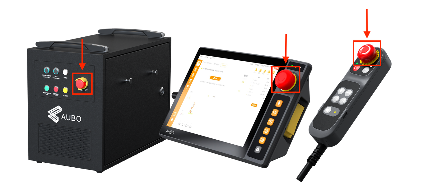 Figure 3-1 Emergency stop buttons on the controller, teach pendant, and control handle
Confirm the equipment state after the emergency stop has been triggered: the robot arm shall come to a stop, the emergency stop indicator on the controller front panel shall light up red, and the teach pendant software interface shall indicate that the robot arm is powered off.
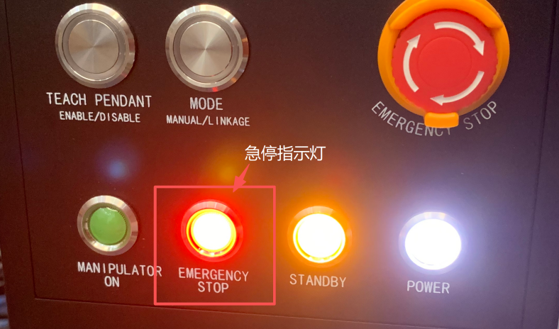 Figure 3-2 Emergency stop indicator
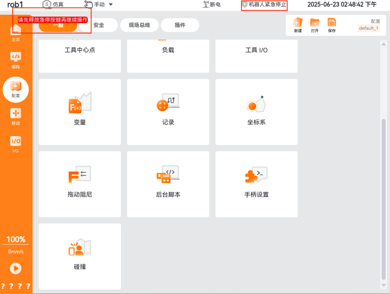 Figure 3-3 Software interface
After completing the test, verify that there are no persons or obstacles in the robot workspace, and check that the fixtures, end-of-arm tooling, and payload are in normal condition.
Then release the emergency stop button and click Power On on the software main page.
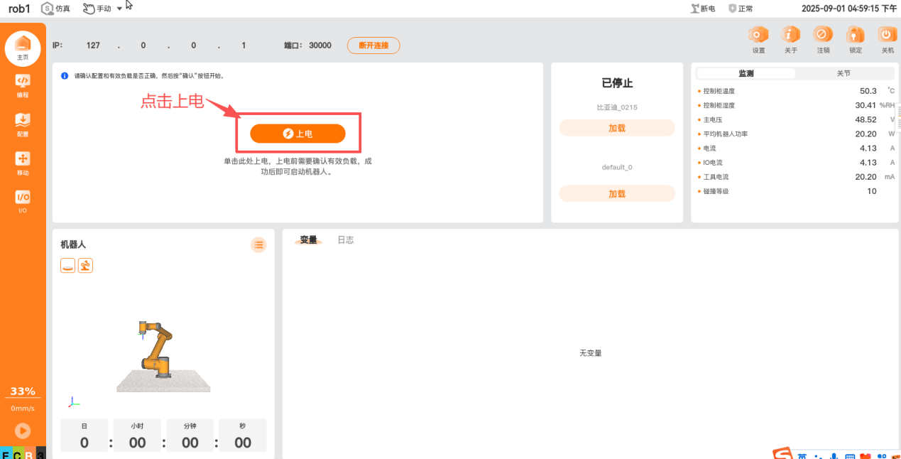 Figure 3-4 Power-on button
Confirm and select the correct payload, then click Continue.
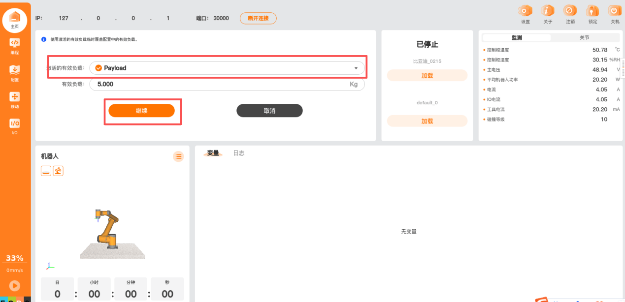 Figure 3-5 Selecting the correct payload
Start the robot and power it up again.
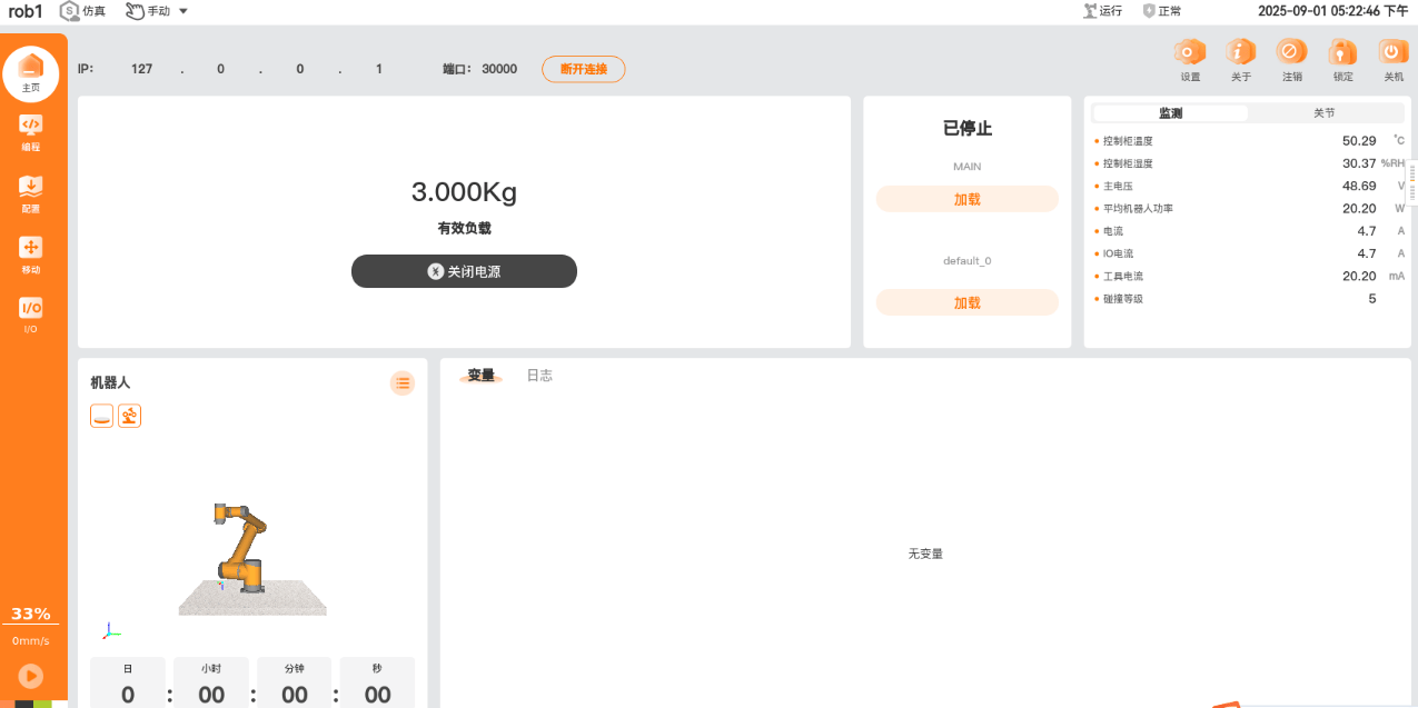 Figure 3-6 Power-on successful
Acceptance Criteria:
The emergency stop function is normal if, after the emergency stop button is pressed, the robot arm stops, the emergency stop indicator lights up red, and the teach pendant software interface indicates that the robot arm is powered off.
3.2.2 Controller Rear Panel Cable Connection Check
Inspection Details:
Check the connection between the robot cable and the controller, between the teach pendant cable and the controller, and between the power cable and the controller respectively, and verify that the three cables are connected correctly and fully seated, as shown in Figure 3-7.
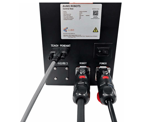
Acceptance Criteria:
The cables are connected to the correct positions and the connectors are fully seated, with no looseness, disconnection, or visible damage.
3.2.3 Panel Indicator Check
Note
This subsection uses the panel indicators of the iS controller as an example. The configuration and state definitions of the panel indicators may differ between controller models. Always refer to the user manual for the corresponding model and to the actual equipment.
Procedure:
After the controller is powered on, the power indicator lights up (POWER, white). Wait until the self-check indicator is continuously lit (STANDBY, yellow); the system is then ready to start, as shown in Figure 3-8.
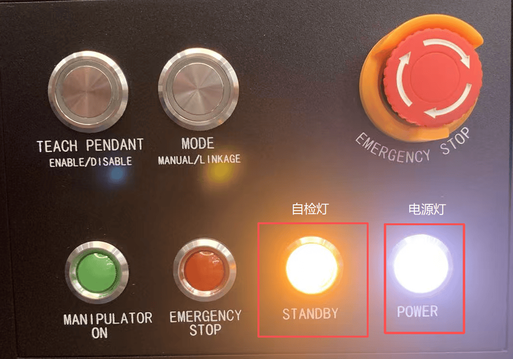 Figure 3-8 Controller power and self-check indicators
During normal robot operation, the power indicator (white) on the controller front panel and the robot arm powered-on indicator (green) are lit, as shown in Figure 3-9.
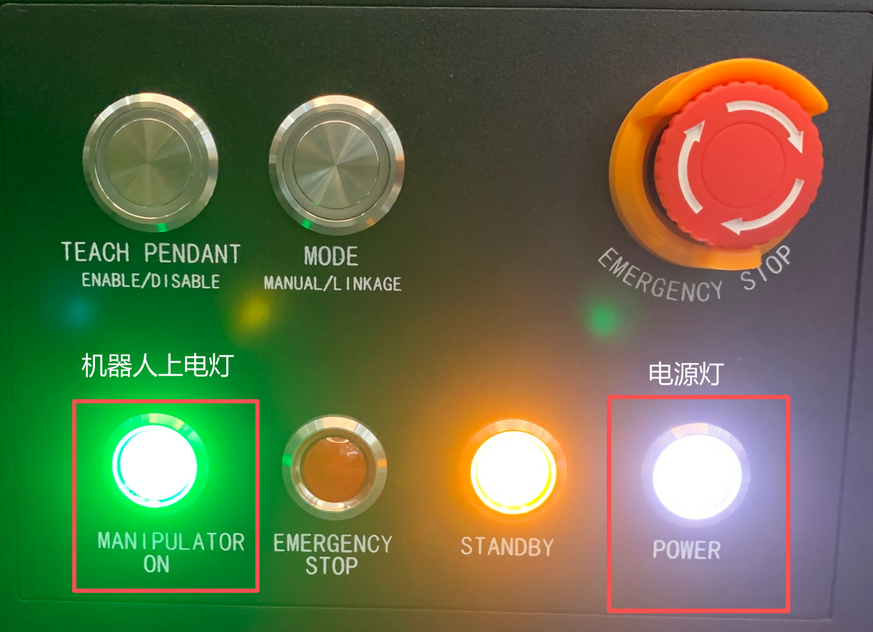 Figure 3-9 Controller power and robot arm powered-on indicators
Acceptance Criteria:
During controller power-on, self-check, and robot operation, the states of the corresponding indicators are consistent with the equipment state, and no abnormal alarm indications are present.
3.2.4 Controller I/O Panel Terminal Wiring Check
Note
This subsection uses the terminals on the I/O panel of the iS controller as an example. The I/O panel layout, terminal assignment, and wiring method may differ between controller models. Always refer to the user manual for the corresponding model and to the actual equipment.
Inspection Details:
Switch off the controller and disconnect the power cable, and take measures to prevent unintended energization. After confirming that residual energy has been discharged and that no hazardous voltage is present, open the controller side door and inspect the I/O terminal panel. Check whether the terminals are fully seated and whether any I/O wiring is loose or disconnected, as shown in Figure 3-10.
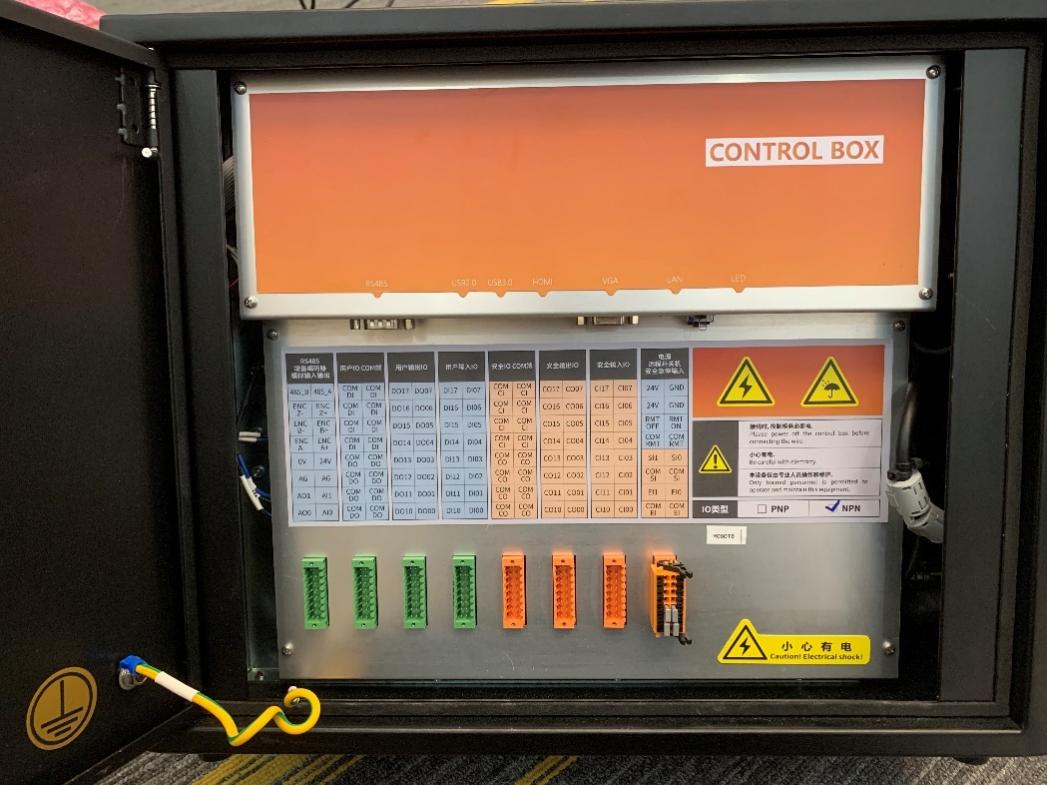
Procedure:
Check the safety I/O terminals. Verify that the default safety I/O jumper on the terminal block on the controller rear panel, or the external hard wiring, is in normal condition, as shown in Figure 3-11.
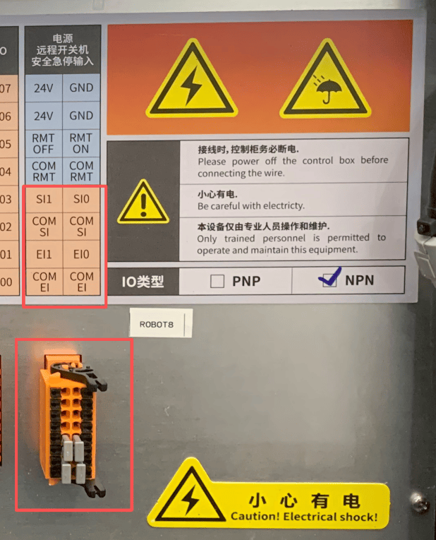 Figure 3-11 Safety I/O terminals
Complete the terminal and wiring check in the de-energized state, then close and lock the controller side door.
Verify that no tools or foreign objects have been left inside the controller.
Restore the power supply to the controller.
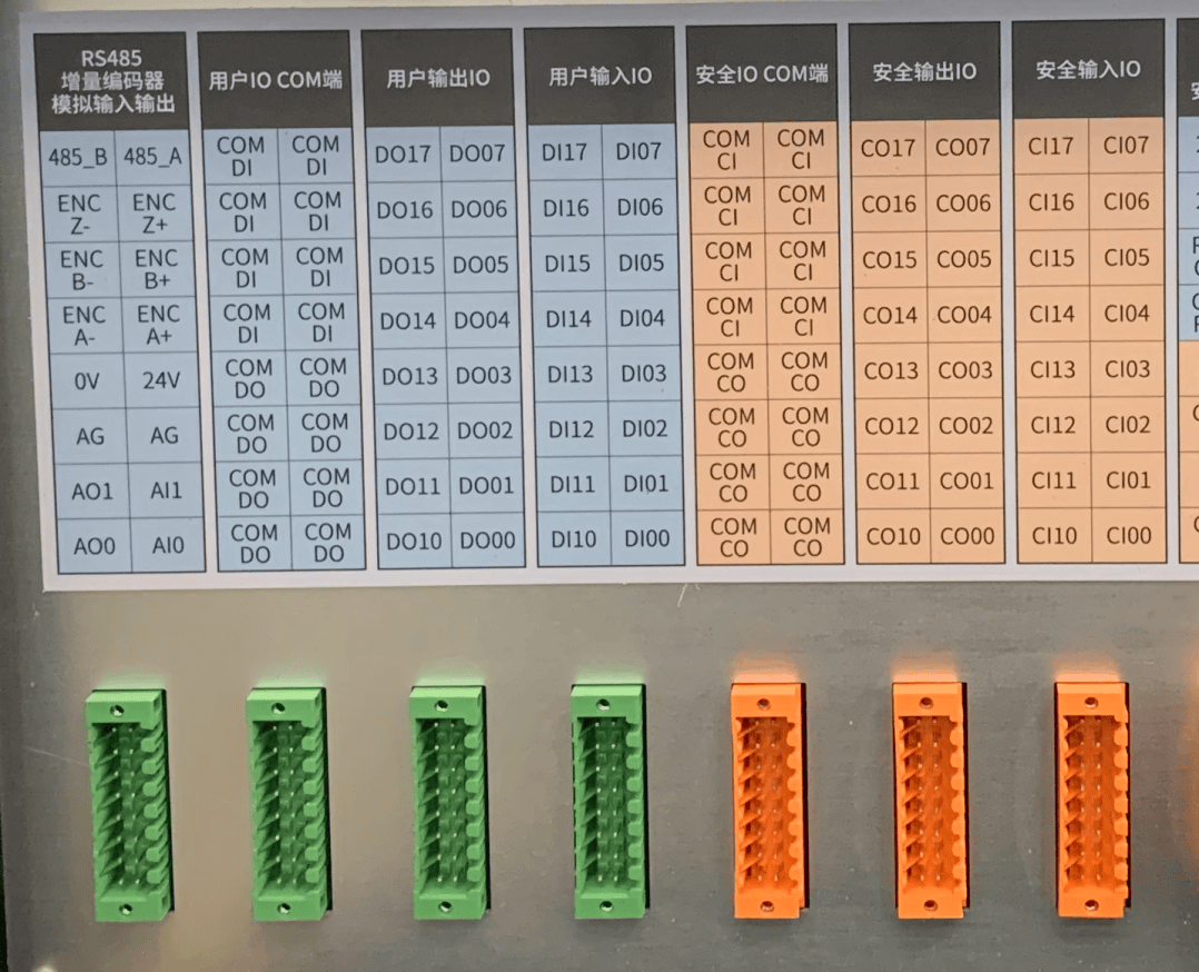
Check the various I/O signals:
- Verify that the general-purpose I/O inputs and outputs operate correctly.
- Check whether the safety I/O and user I/O are in a valid state.
- Verify that the signals can be triggered through the teach pendant interface or external equipment.
As shown in Figure 3-12.
Acceptance Criteria:
The terminals are wired securely, with no looseness or disconnection; the safety I/O and user I/O are in a normal state and can be triggered as intended.
3.3 Visual Inspection
Visual inspection is used to confirm that the terminals, cables, fasteners, external parts, and interfaces of the controller and robot arm are in normal condition. Before the inspection, make sure that the equipment is in a safe state and disconnect the relevant power supply according to the item being inspected.
3.3.1 Controller Visual Inspection
Procedure:
Disconnect the AC power cable of the controller and take measures to prevent unintended energization. Wait for the residual energy to discharge as required by the equipment, and confirm that no hazardous voltage is present before starting the internal inspection.
Check whether any internal terminals of the controller are loose, and whether any cables are damaged or have come out of their terminals.
Check whether the fixing screws of all circuit boards inside the controller are loose.
Check whether the interior of the power supply unit contains dirt or dust. If cleaning is required, use an anti-static vacuum cleaner.
Check whether the heavy-duty cable is damaged and whether the heavy-duty connector is loose.
Check whether the AC power cable is damaged or severely softened.
Check whether all connectors on the controller are loose or damaged.
Acceptance Criteria:
The internal terminals, cables, circuit board fasteners, power supply unit, heavy-duty cable, AC power cable, and external interfaces of the controller show no looseness, disconnection, damage, heavy soiling, or other abnormalities.
3.3.2 Robot Arm Visual Inspection
Visual inspection of the robot arm is used to confirm that the robot arm cables, mounting bolts, and external parts are in normal condition. If the torque values or other technical data of the robot need to be adjusted after the inspection, refer to the user manual for the corresponding model or to the requirements in the maintenance sections of this manual.
Procedure:
If possible, move the robot arm to its home position.
Switch off the controller and disconnect its power cable.
Check whether the cable between the controller and the robot arm is damaged.
Check whether the robot arm base mounting bolts are correctly tightened.
Check whether the tool flange bolts are correctly tightened.
Check whether the external parts of the robot arm are worn or damaged. If any external part is worn or damaged, replace it promptly.
| Symbol | Instruction |
|---|---|
| If any damage is found on a robot that is within its warranty period, contact an AUBO-authorized distributor or the AUBO after-sales service team. |
Acceptance Criteria:
The robot arm cables are undamaged, the base mounting bolts and tool flange bolts are properly tightened, and the external parts show no signs of obvious wear, deformation, or damage.
3.4 Cleaning
3.4.1 General Cleaning
If dust, dirt, or oil is observed on the controller or the robot arm, wipe the external surfaces of the equipment with a lint-free cloth or alcohol, and check the external surfaces for defects such as blemishes.
- Before cleaning, make sure that the equipment is in a safe state, and avoid cleaning while the equipment is running.
- While cleaning, simultaneously check the external surfaces for defects such as scratches, deformation, damage, or residual oil.
| Symbol | Instruction |
|---|---|
| Never clean the interior of the controller with a compressed-air gun, as this may damage internal components or create a risk of electrical short circuit. |
3.4.2 Fan Cleaning
Fan cleaning is performed to ensure that the controller cooling air path is unobstructed and to prevent poor heat dissipation caused by dust accumulation. Check the fan operating state and the airflow at the air inlet and outlet before cleaning, and perform the cleaning only after the controller has been de-energized.
Inspection Requirements:
After the controller is powered on, check whether the internal fan and the rear panel fan of the controller rotate normally.
Check whether the airflow at the exhaust outlet and intake opening is normal, and confirm that there is no obvious abnormal noise, jamming, or dust blockage, as shown in Figure 3-13.
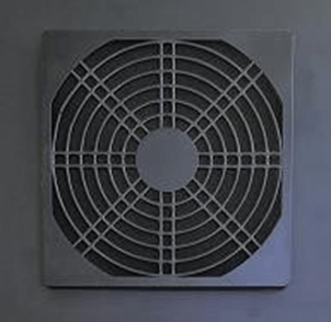 Figure 3-13 Controller fan
Cleaning Procedure:
Switch off the controller and disconnect the power cable. Wait until the fan has stopped rotating before proceeding.
Manually remove the rear housing of the fan on the controller rear panel, as shown in Figure 3-14.
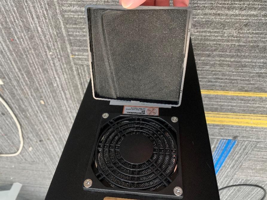 Figure 3-14 Controller rear panel fan housing
Take out the foam filter and remove the dust from the foam filter and the fan housing, as shown in Figure 3-15.
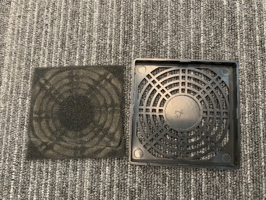 Figure 3-15 Fan foam filter
After cleaning, reinstall the foam filter and the fan housing in position and verify that they are firmly seated.
After the controller is powered on again, check whether the fan rotation and the airflow at the intake and exhaust openings have returned to normal.
Acceptance Criteria:
The cooling fan rotates normally, the airflow at the exhaust outlet and intake opening is normal, and there is no obvious abnormal noise, jamming, dust blockage, or loose installation.
4 Repair and Replacement of Parts
4.1 Maintenance and Replacement Notes
This section describes the tool preparation and electrostatic discharge (ESD) protection requirements that apply before maintenance and replacement work. Before maintaining or replacing the internal boards, cables, power supply units, or other components of the controller, make sure that all required tools are available and that ESD protection is in place as specified.
4.1.1 Installation and Maintenance Tools
The following anti-static safety tools are recommended when installing and maintaining the controller and the robot arm:
- Flat-head screwdriver
- Phillips-head screwdriver
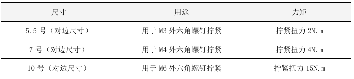
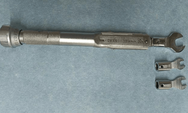
- Small open-end wrenches (sizes 5.5, 7, and 10)
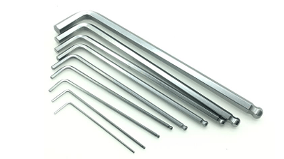
- Hex key set
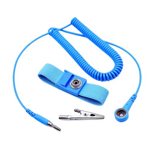
- Anti-static wrist strap
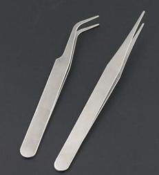
- Tweezers
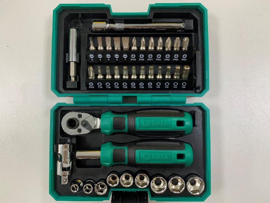
4.1.2 Electrostatic Discharge (ESD) Protection Requirements
Components inside the controller, such as the PCBA boards, interface boards, main control board, hard disk, and memory modules, are susceptible to damage from electrostatic discharge (ESD). To reduce the risk of ESD damage, observe the following requirements when maintaining or replacing such components.
Basic Requirements:
Switch off the equipment before starting work, and confirm that the relevant components are in a safe state.
Work on a floor that is not carpeted, and use an anti-static work surface such as a conductive foam mat or an ESD-safe bench top.
Wear the anti-static wrist strap on the operator's wrist and connect the strap to the system earth ground to discharge static electricity from the body.
Keep ESD-sensitive components in their original packaging or anti-static bags until they are installed.
Place removed components promptly into the original metallized plastic bag, a metal box, or other anti-static packaging material.
Circuit Board Handling Requirements:
Place the removed old board into a spare anti-static bag, as shown in Figure 4-6.
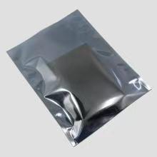 Figure 4-6 Anti-static bag
Take the new board out of the anti-static bag and prepare it for installation.
Hold ESD-sensitive components by their edges, avoiding contact with the circuit board pins, conductors, or electronic components.
If an ESD-sensitive component must be put down temporarily, place it in a dedicated anti-static bag first. Do not place it directly on a non-conductive material or on a metal bench top.
In cold weather, or when heating equipment reduces the ambient humidity, the risk of static discharge increases. Take extra care to apply ESD protection in such conditions.
| Symbol | Instruction |
|---|---|
| Machine covers and metal bench tops may be electrically grounded and can form a discharge path through a component, increasing the risk of damage. Always use a compliant anti-static work surface and anti-static packaging material throughout the maintenance procedure. |
4.2 Controller Maintenance
This section describes the safe operating requirements for controller maintenance and replacement work, together with the basic procedure for replacing a complete controller cabinet. Before maintaining or replacing the controller, make sure that the equipment is in a safe state and complete a data backup as required.
4.2.1 Safe Operation Instructions
The controller contains components such as PCBA boards, interface boards, and the main control board that are susceptible to ESD damage. Observe the following safe operating requirements before maintaining or replacing any internal component of the controller.
| Symbol | Instruction |
|---|---|
| Before installing a new I/O expansion board, verify that the interface board version number and the version of the loaded program are exactly identical to those of the original board. Otherwise, the customer shall bear responsibility for any resulting consequences. |
| Wear the anti-static wrist strap throughout the entire procedure when replacing a PCBA board inside the controller. Keep PCBA boards sealed in anti-static bags and do not touch the components on a PCBA board. |
Operating Requirements:
Switch off the equipment before starting work, and confirm that the relevant components are in a safe state.
Perform the work on a floor that is not carpeted, and use an anti-static work surface such as a conductive foam mat, an ESD-safe bench top, an anti-static plastic bag, or an ESD-safe turnover box.
Place the removed component into the original metallized plastic bag, a metal box, or other anti-static packaging material, as shown in Figure 4-7.
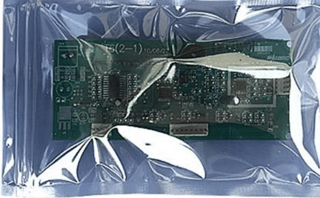 Figure 4-7 Anti-static packaging material
Wear the anti-static wrist strap on the operator's wrist and connect it reliably to earth ground to discharge static electricity from the body, as shown in Figure 4-8.
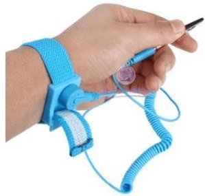 Figure 4-8 Wearing the anti-static wrist strap
When removing or installing a circuit board, hold it as much as possible by its edges and avoid touching the board pins or conductors, as shown in Figure 4-9.
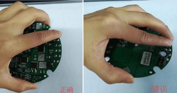 Figure 4-9 Handling a circuit board
Test equipment used for checking circuit boards must be reliably grounded.
Do not cover the commissioning bench with ordinary vinyl plastic sheeting, and do not use plastic work chairs.
Commissioning personnel shall not wear synthetic fiber work clothes. Cotton work clothes or anti-static work clothes are recommended.
4.2.2 Replacing the Complete Controller Cabinet
Before replacing a complete controller cabinet, verify that no other electrical devices or circuits are externally connected inside the controller, and complete a system backup in advance. Before replacing the controller or an internal PCB board, confirm the plan with AUBO.
| Symbol | Instruction |
|---|---|
| Before replacing the complete cabinet, verify that no other electrical devices or circuits are externally connected inside the controller. AUBO shall not be liable for any loss caused otherwise. |
Preparation:
Confirm with AUBO that the plan for replacing the controller or an internal PCB board is correct.
Perform a system backup of the original controller and verify that the backup files are usable.
Verify that the model, cable interfaces, and configuration of the new controller match the on-site equipment.
Cabinet Replacement Procedure:
Shut down the controller from the teach pendant and turn the shutdown knob to the OFF position, as shown in Figure 4-10.
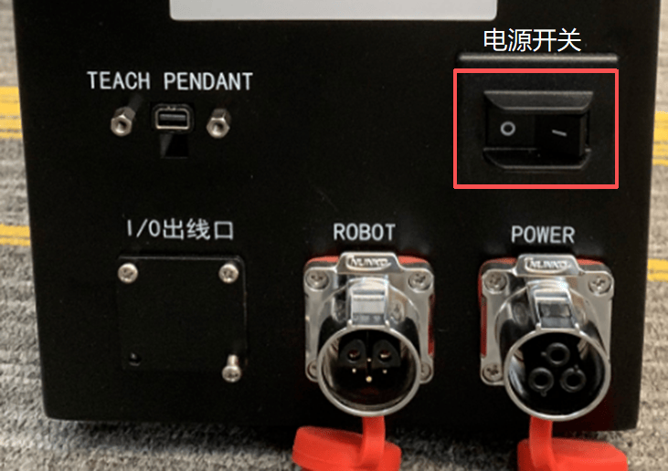 Figure 4-10 Controller shutdown knob
Carefully unplug the aviation connectors of the teach pendant, the power supply, and the robot arm.
Replace the controller with the new one, connect the corresponding cable connectors, and verify that the connection positions are correct and that the connectors are securely locked.
Power on the system and confirm that the controller starts up normally.
Copy the system backup files to the corresponding folder on the new controller to complete the controller cabinet replacement.
Inspection Requirements:
After the controller has been replaced, verify that the cable connections are secure, that the controller starts up normally, that the system backup files have been restored to their corresponding locations, and that the equipment operating state shows no abnormalities.
4.2.3 Replacing the I/O Board
Before replacing the I/O board, switch off the controller and disconnect the external power supply. Record the positions of the cables and terminals during removal so that they can be reconnected correctly during reassembly.
Replacement Procedure:
Open the controller side door with the key supplied with the controller. Turn the key 90° counterclockwise to open the cabinet door, as shown in Figure 4-11.
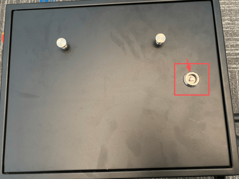 Figure 4-11 Controller side door
After opening the cabinet door, unplug the I/O terminal wiring. Use a Phillips screwdriver to remove the four screws along the edge of the I/O panel cover and take off the panel cover, as shown in Figure 4-12.
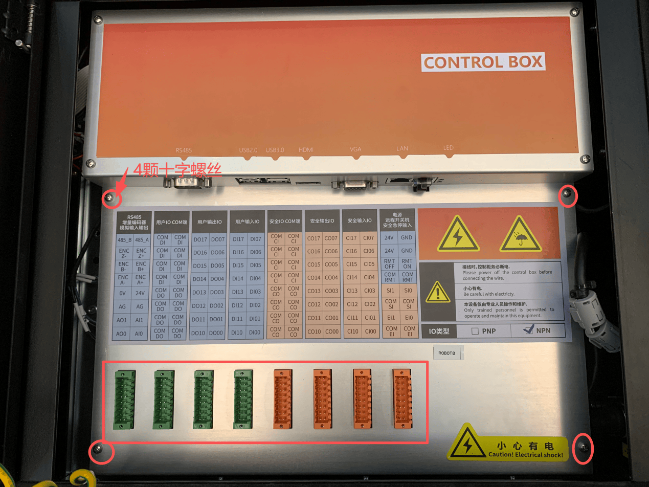 Figure 4-12 Controller panel
Remove the fixing screws of the I/O board and gently pull out the ribbon cable to take off the I/O board, as shown in Figures 4-13 and 4-14.
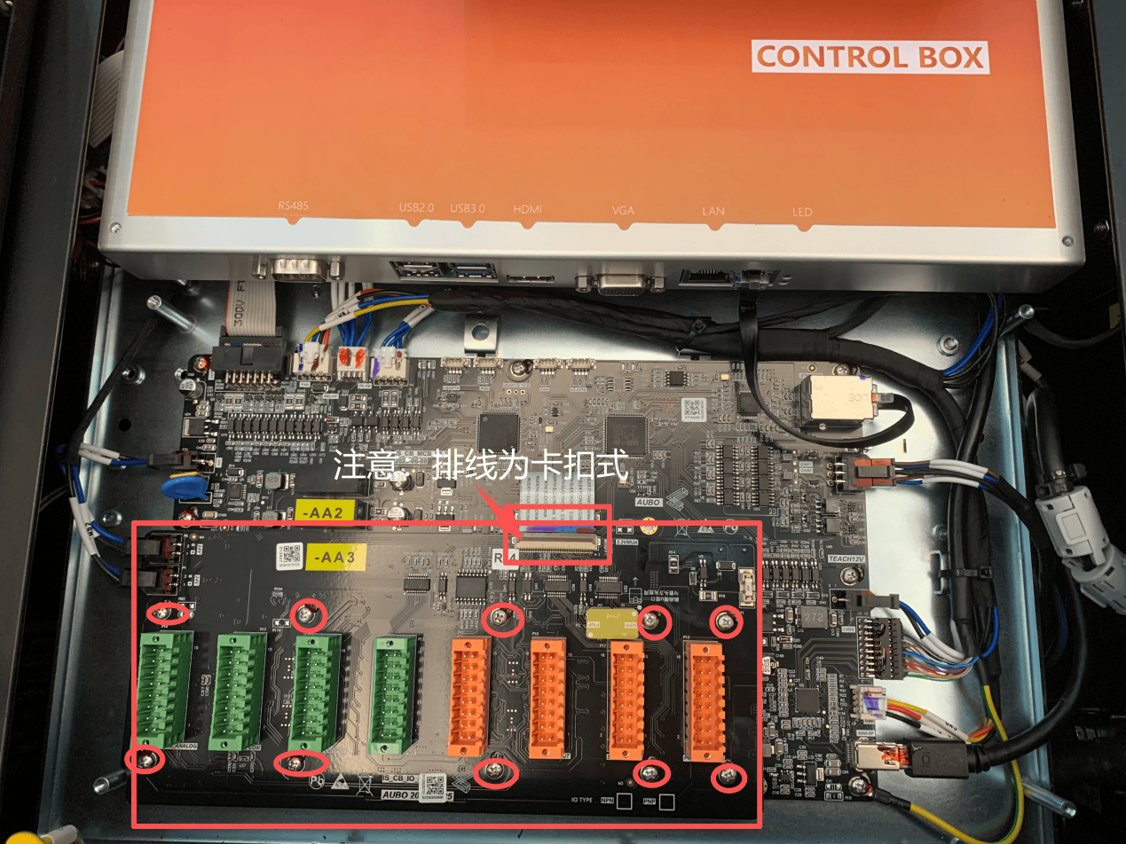 Figure 4-13 Removing the I/O board
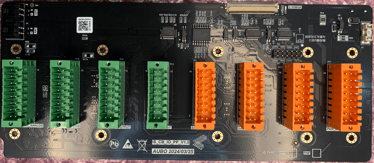 Figure 4-14 I/O board
Install the new I/O board and restore the ribbon cable, fixing screws, panel cover, and I/O terminal wiring in the reverse order of removal. After confirming that no tools or foreign objects have been left behind, close and lock the controller side door.
Inspection Requirements:
After the I/O board has been replaced, verify that the board is firmly secured, that the ribbon cable is reliably seated, that the I/O terminal wiring has been restored correctly, and that the I/O functions operate normally once the controller is powered on.
4.2.4 Replacing the Safety Interface Board
Before replacing the safety interface board, disconnect the robot from the external power supply.
| Symbol | Instruction |
|---|---|
| Before installing a new interface board, verify that the interface board version number and the version of the updated program are exactly identical to those of the original board. Otherwise, the customer shall bear responsibility for the resulting consequences. |
Replacement Procedure:
Disconnect the robot from the external power supply and remove the top cover of the controller, as shown in Figure 4-15.
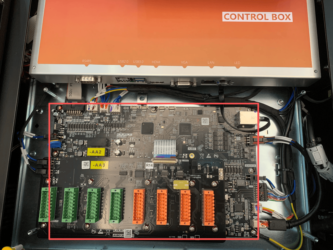 Figure 4-15 Top cover of the controller
Remove the fixing screws of the interface board one by one, then detach the surrounding terminal connectors to take out the interface board, as shown in Figure 4-16.
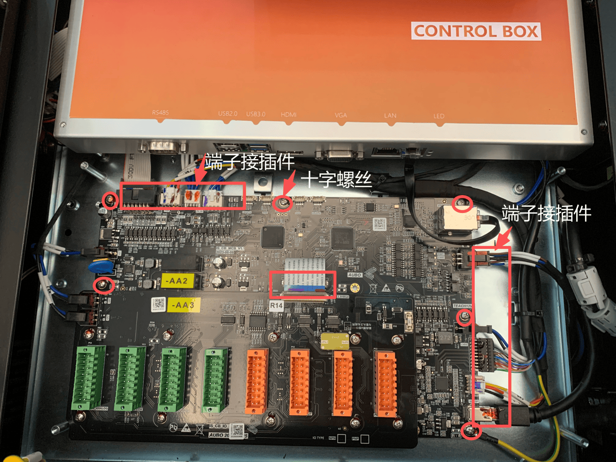 Figure 4-16 Removing the interface board
Take out the old interface board and place a new interface board, with the program already pre-loaded, in the corresponding position, as shown in Figure 4-17.
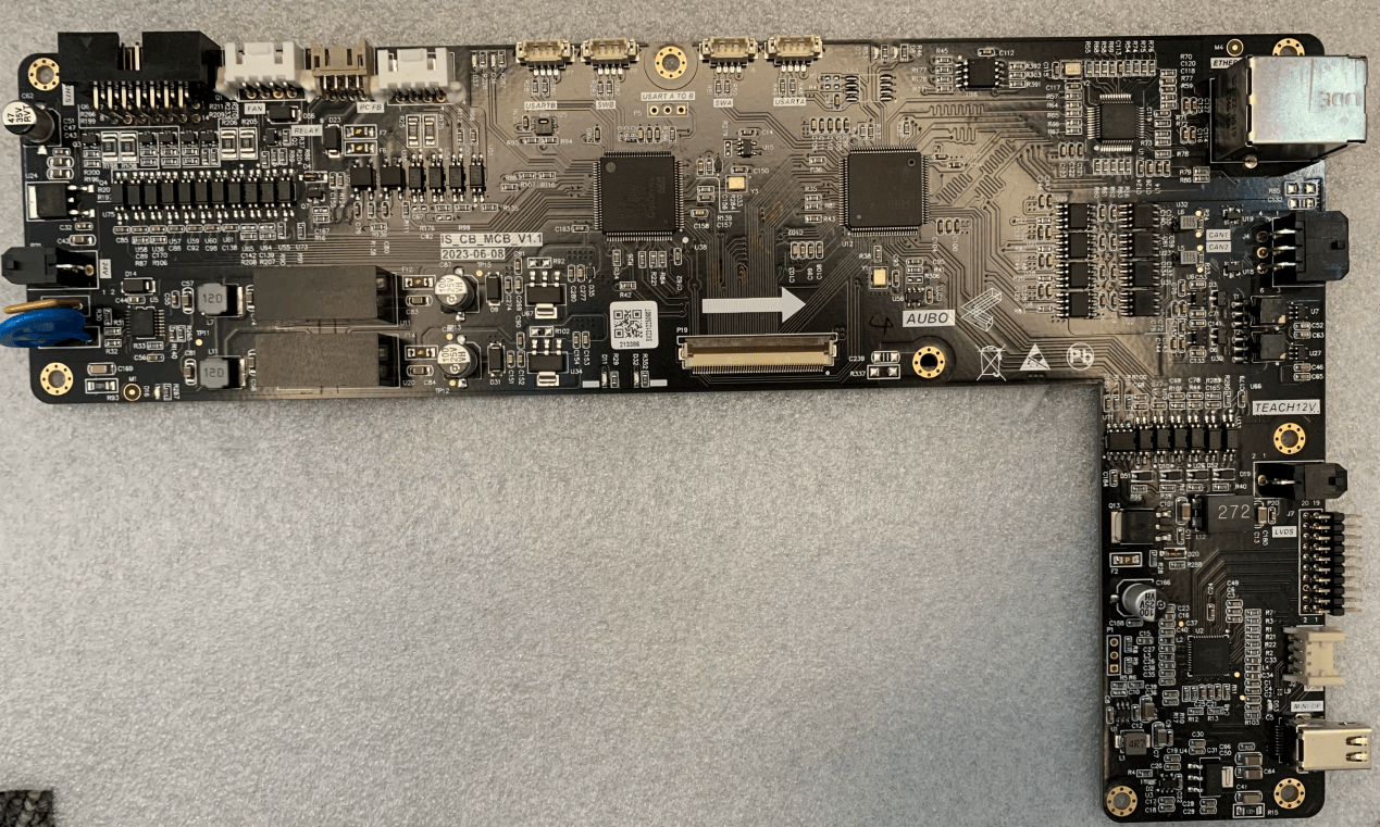 Figure 4-17 Safety interface board
Reinstall the fixing screws in the reverse order of removal and fully seat the terminal connector ribbon cables. After confirming that no tools or foreign objects have been left behind, refit and secure the top cover of the controller to complete the replacement of the safety interface board.
Inspection Requirements:
After the safety interface board has been replaced, verify that the board is firmly secured, that the terminal connector ribbon cables are reliably seated, that the program version matches the original version, and that the safety interface functions operate normally once the equipment is powered on.
4.2.5 Replacing the Main Control Board
Before replacing the main control board, disconnect the robot from the external power supply and record the cable connection positions of the main control board. Wear the anti-static wrist strap throughout the removal and installation procedure to avoid ESD damage to the board.
Replacement Procedure:
Disconnect the robot from the external power supply and open the top panel of the controller; the industrial main board is then visible, as shown in Figure 4-18.
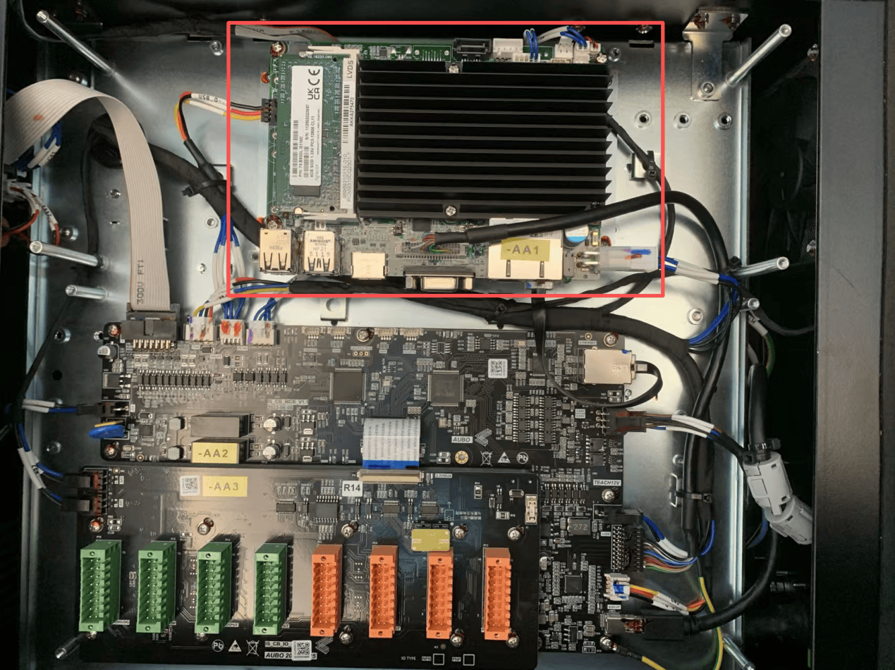 Figure 4-18 Location of the industrial main board
Remove the four fixing screws on the main control board one by one, gently unplug the cables connected to the board, and take off the main control board, as shown in Figure 4-19.
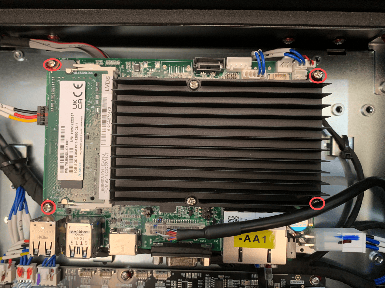 Figure 4-19 Removing the main control board
After removing the main control board, remove the memory module and the hard disk in sequence by following the removal procedure for these components in Section 4.2.6.
Install the original memory module and hard disk onto the new main control board, then restore the main control board, the plug-in cables, and the fixing screws in the reverse order of removal. After confirming that no tools or foreign objects have been left behind, refit and secure the top panel of the controller to complete the replacement of the main control board.
Inspection Requirements:
After the main control board has been replaced, verify that the board is firmly secured, that the cables are connected correctly and reliably, that the memory module and hard disk are properly installed, and that the controller powers up and starts normally.
4.2.6 Replacing the Hard Disk and the Memory Module
Both the hard disk and the memory module are installed on the main control board. The memory module is located on the front of the main control board and the hard disk on the rear. Switch off the equipment and apply ESD protection before replacement.
Replacement Procedure:
Disconnect the robot from the external power supply and open the top panel of the controller as described in Step 1 of Section 4.2.5; the industrial main board is then visible, as shown in Figure 4-20.
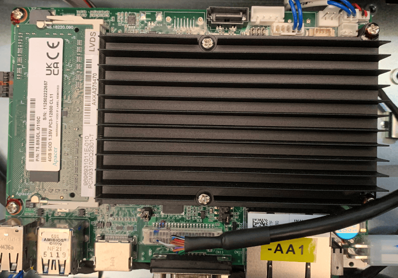 Figure 4-20 Main control board
Gently release the retaining clips of the memory module on both sides and remove the memory module, as shown in Figure 4-21.
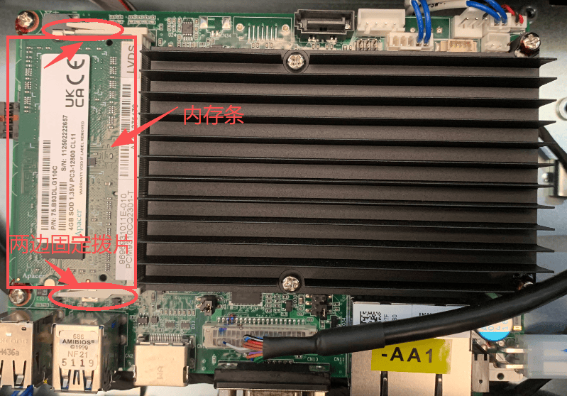 Figure 4-21 Removing the memory module
Remove the two hard disk fixing screws on the rear of the main board and take off the hard disk, as shown in Figure 4-22.
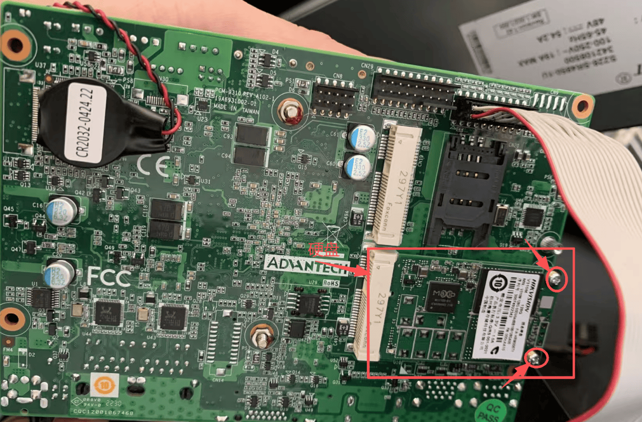 Figure 4-22 Removing the hard disk
Store the removed hard disk and memory module in anti-static bags.
Install the new hard disk and the new memory module in sequence. When installing the hard disk, insert it at an angle of approximately 45° until it is fully seated, then tighten the two fixing screws. After inserting the memory module, make sure that the retaining clips on both sides are properly engaged.
Refit the main control board and the controller cover in the reverse order of removal to complete the replacement of the hard disk and the memory module.
Inspection Requirements:
After the hard disk and the memory module have been replaced, verify that the hard disk fixing screws are tightened and that the memory module retaining clips are properly engaged, and check that the controller powers up normally and that the system starts and recognizes the storage devices correctly.
4.2.7 Replacing the DC48V and DC24V Power Supplies
Before replacing the DC48V or DC24V power supply, switch off the controller and disconnect the external power supply. Record the order of the corresponding wires before disconnecting them, so that they can be reconnected correctly during reassembly.
Replacement Procedure:
With the controller de-energized, remove the Phillips screws around the side cover of the controller and open the side cover, as shown in Figure 4-23.
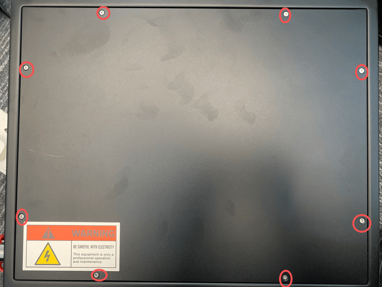 Figure 4-23 Controller side cover
Once the cover is open, the DC48V and DC24V power supplies are visible, as shown in Figure 4-24.
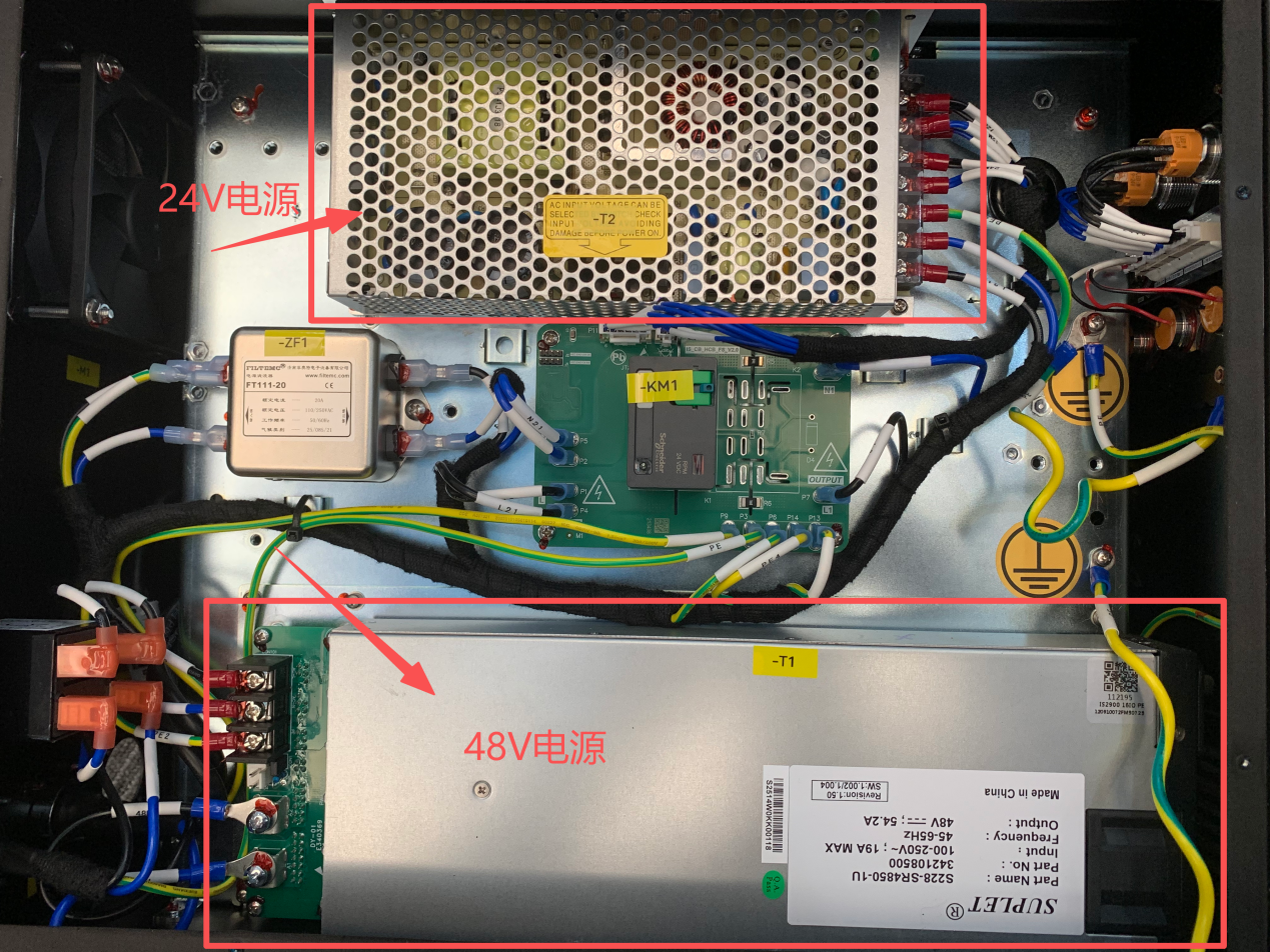 Figure 4-24 Location of the DC48V and DC24V power supplies
Record the connection order of the power supply wires.
Remove the screws beneath the sheet metal bracket that secures the DC48V or DC24V power supply, together with the wires connected to the power supply, to take off the corresponding power supply, as shown in Figures 4-25 and 4-26.
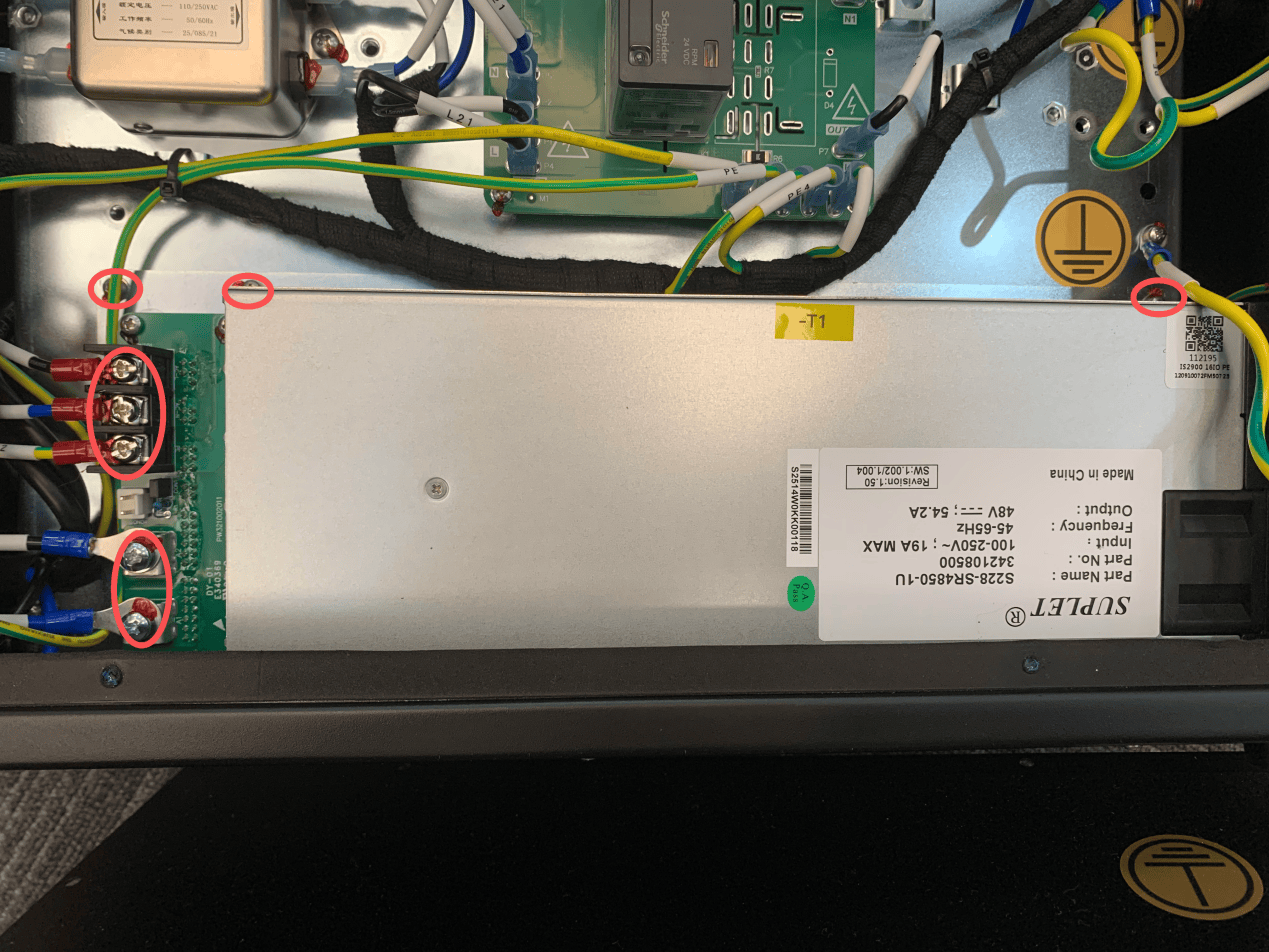 Figure 4-25 Removing the DC48V power supply
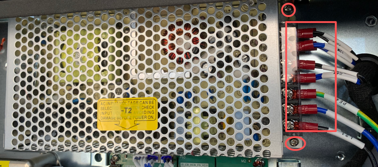 Figure 4-26 Removing the DC24V power supply
Take out the old power supply, install the new one, reconnect the power supply wires in the recorded order, and tighten the fixing screws.
Refit the screw cover and secure it with thread locker; reattach the power supply module and the aluminum alloy back plate to the controller with screws.
After verifying that the power supply module, the aluminum alloy back plate, and the controller side cover are all firmly installed and that no tools or foreign objects have been left behind, power on the controller and confirm that the equipment starts up normally to complete the power supply replacement.
Inspection Requirements:
After the power supply has been replaced, verify that the wires are connected in the correct order, that the fixing screws are tightened, and that the cover is securely installed, and check that the controller powers up and starts normally.
4.3 Robot Arm Maintenance
This section uses the AUBO-i series products as examples to describe the structure of the robot arm, the precautions for replacing joint modules, and the removal and installation methods for the end effector and for the 14, 17, 25, and 32 modules.
CAUTION
Replacing robot arm modules involves electrical connections, sealing structures, and mechanical positioning. Before starting work, make sure that the power supply has been disconnected and that anti-static measures are in place.
4.3.1 Structure of the Robot Arm
The structure of the robot arms of the AUBO-i series products i3 / i5 / i7 / i10 / i12 / i16 / i20 is shown in Figure 4-27.

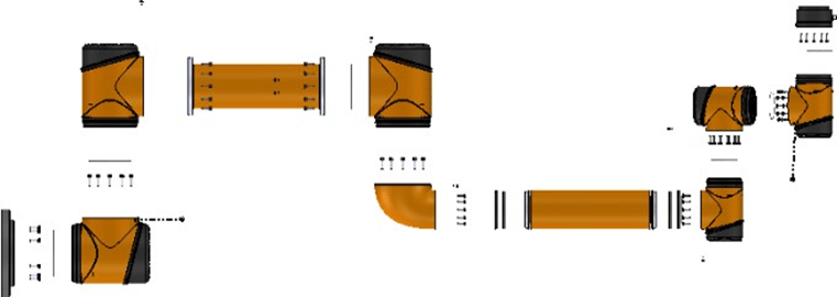
The module combinations of the AUBO-i series are listed in Table 4-1.
| Module combination | Joint 1 | Joint 2 | Joint 3 | Joint 4 | Joint 5 | Joint 6 |
|---|---|---|---|---|---|---|
| i3 | 20 module | 20 module | 17 module | 14 module | 14 module | 14 module |
| i5 | 25 module | 25 module | 25 module | 14 module | 14 module | 14 module |
| i7 | 25 module | 25 module | 25 module | 14 module | 14 module | 14 module |
| i10 | 32 module | 32 module | 25 module | 17 module | 14 module | 14 module |
| i12 | 25 module | 25 module | 25 module | 17 module | 17 module | 17 module |
| i16 | 32 module | 32 module | 25 module | 17 module | 14 module | 14 module |
| i20 | 40 module | 40 module | 32 module | 20 module | 20 module | 20 module |
4.3.2 Replacement Notes
| Symbol | Instruction |
|---|---|
| 1. AUBO generally does not recommend that customers replace an individual robot arm joint themselves. AUBO shall not be liable for any loss incurred during the disassembly or replacement of an individual joint carried out by the customer. 2. Before replacing an individual joint, confirm the plan with AUBO and obtain its permission. The joint module must be replaced with the equipment de-energized. |
Complete the following preparations before starting the replacement:
- Prepare the repair kit, including torque tools and the anti-static wrist strap.
- Read and fully understand this guide.
- Move the robot arm to a position that facilitates removal. If necessary, remove the complete unit from the work cell and place it on a solid, level surface.
- Switch off the power supply and remove the rear cover by following the corresponding procedure.
4.3.3 Removing the End Effector
Required Tools: 2.5 mm hex key, size 5.5 open-end wrench, 2 mm flat-head screwdriver, tweezers.
Procedure:
Perform the shutdown operation on the teach pendant to power off the robot arm.
Prepare the tools required for removal.
Fold the rubber ring between joint 6 and the end effector back onto the joint, and retract the decorative ring to expose the fixing screws.
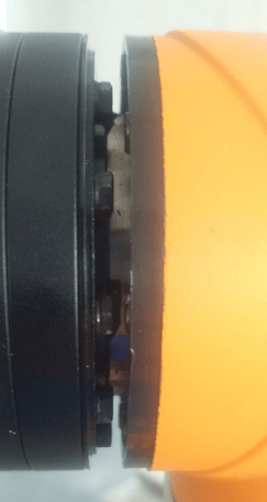 Figure 4-28 Folding back the end effector rubber ring
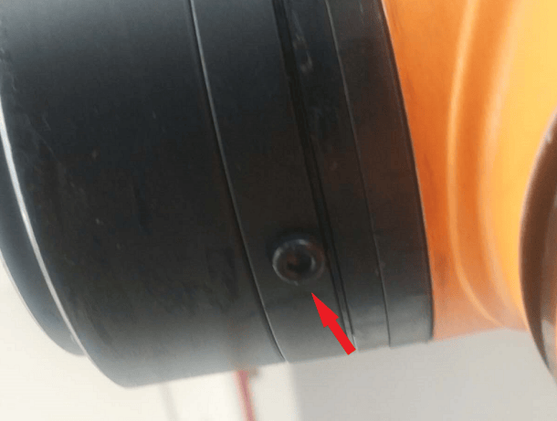 Figure 4-29 Retracting the end effector decorative ring
Use the 2.5 mm hex key to remove the limit screw of joint 6.
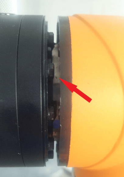 Figure 4-30 Removing the limit screw of joint 6
Use the size 5.5 open-end wrench to loosen the ten flange fixing screws between joint 6 and the end effector until they are halfway out. Hold both ends of the joint with the left and right hands and rotate them in opposite directions until the mechanical stop is reached (the holes are keyhole-shaped). Then unplug the power terminal and the CAN terminal and remove the end effector.
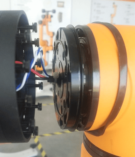 Figure 4-31 Loosening the end effector flange fixing screws
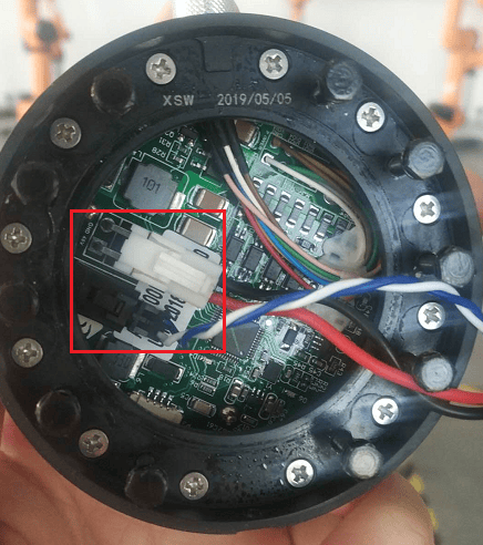 Figure 4-32 End effector removal complete
4.3.4 Installing the End Effector
Procedure:
Before installation, verify that the sealing rubber ring on the flange of joint 6 is seated in the groove.
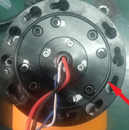 Figure 4-33 Checking the sealing ring on the joint 6 flange
Verify that the wires at the joint 6 flange are secured with cable ties.
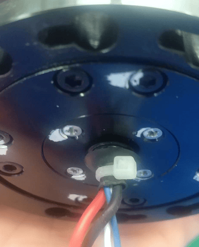 Figure 4-34 Checking the wire securing condition at the joint 6 flange
Replace the ten screws on the end effector with new screws (M3 × 14 mm), apply thread locker to the new screws, and leave the screws protruding by approximately 10 mm.
Insert the 48V and GND power terminals and the blue/white CAN terminal at the flange end of joint 6 into the corresponding interfaces on the end effector.
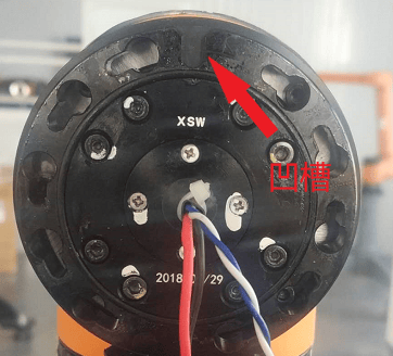 Figure 4-35 Connecting the end effector power and CAN terminals (1)
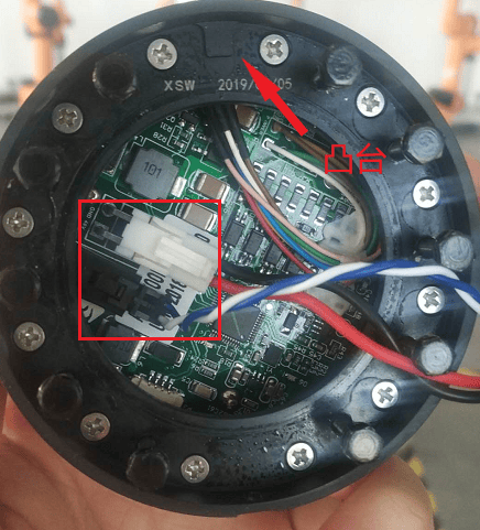 Figure 4-36 Connecting the end effector power and CAN terminals (2)
Insert the screws into their corresponding holes. Align the boss inside the joint with the groove of the forearm tube, keep the orientation consistent, and take care not to pinch the wires. Then drive the screws into the small holes and pre-tighten all ten screws. When pre-tightening, apply force to the joint to prevent it from loosening at the small holes. Finally, tighten the screws in a diagonal sequence.
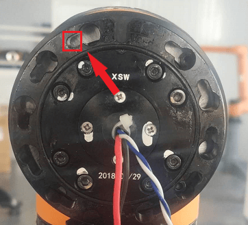 Figure 4-37 Tightening the end effector flange fixing screws
Use the 2.5 mm hex key to reinstall the limit screw of joint 6.
Return the decorative ring and the rubber ring to their original positions to complete the installation of the end effector.
4.3.5 Removing the 14 Module
This section uses the removal of joint 5 as an example to describe how to remove the 14 module.
Required Tools: 2.5 mm hex key, size 5.5 open-end wrench, 2 mm flat-head screwdriver, tweezers.
Procedure:
Manually move the robot arm on the teach pendant to a posture that facilitates removal, then perform the shutdown operation to power off the robot arm.
Prepare the tools required for removal.
Use the 2.5 mm hex key to remove the three hexagon socket screws on the rear covers of joints 5 and 6.
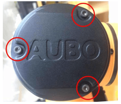 Figure 4-38 Removing the rear cover screws of joints 5 and 6
Unplug the blue/white CAN terminals of joints 5 and 6, and use a small flat-head screwdriver to disconnect the 48V and GND power wires.
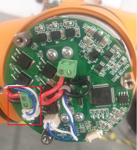 Figure 4-39 Disconnecting the cables of joints 5 and 6
Fold the rubber ring at the joint connector back onto the joint.
Fold the rubber ring between joints 4 and 5 back onto the joint, and retract the decorative ring to expose the fixing screws.
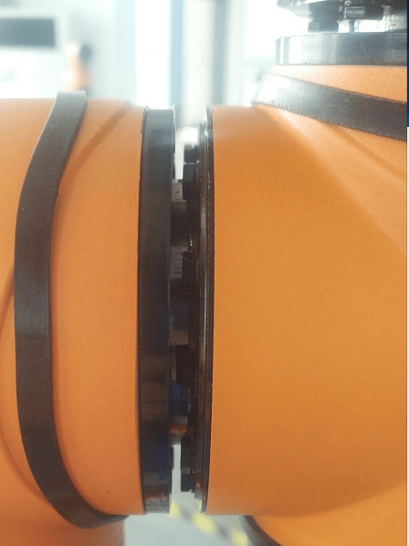 Figure 4-40 Retracting the decorative ring at the 14 module joint
Use the 2.5 mm hex key to remove the two limit screws of joints 5 and 6.
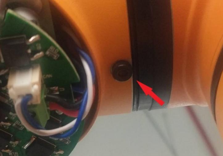 Figure 4-41 Removing the limit screw of joint 5
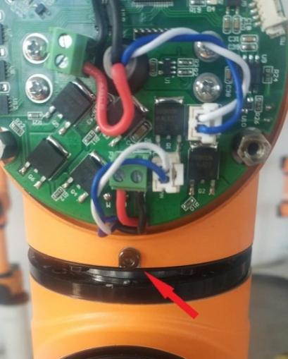 Figure 4-42 Removing the limit screw of joint 6
Use the size 5.5 open-end wrench to loosen the ten flange fixing screws between joints 5 and 6 until they are halfway out. Hold both ends of the joint with the left and right hands, lift upward slightly, and rotate them in opposite directions until the mechanical stop is reached (the holes are keyhole-shaped). Then remove joint 6 together with the end effector. During removal, gently pull out the two red/black 48V power wires and the blue/white CAN wire, taking care not to break them.
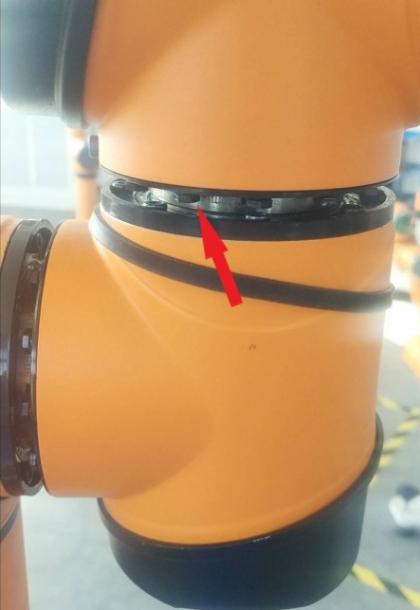 Figure 4-43 Loosening the flange fixing screws between joints 5 and 6
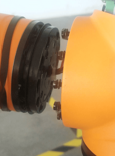 Figure 4-44 Removing joint 6 and the end effector
In the same way, use the size 5.5 open-end wrench to loosen the ten flange fixing screws between joints 4 and 5 until they are halfway out. Hold both ends of the joint with the left and right hands and rotate them in opposite directions until the mechanical stop is reached (the holes are keyhole-shaped). Then remove joint 5. During removal, gently pull out the two red/black 48V power wires and the blue/white CAN wire, taking care not to break them.
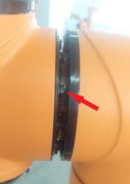 Figure 4-45 Loosening the flange fixing screws between joints 4 and 5
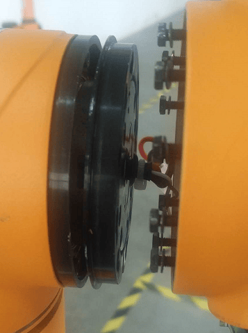 Figure 4-46 Removing the joint 5 14 module
Take off the 14 module to complete the module removal.
4.3.6 Installing the 14 Module
Procedure:
Take a module with the same ID and specification. Before installation, verify that the sealing rubber rings on the flanges of joints 4 and 5 are seated in their grooves.
Figure 4-47 Checking the flange sealing ring of the 14 moduleVerify that the wires at the joint 5 flange are secured with cable ties.
Figure 4-48 Checking the wire securing condition at the joint 5 flangeReplace the ten screws on the joint with new screws (M3 × 14 mm), apply thread locker to the new screws, and leave the screws protruding by approximately 10 mm.
Feed the 48V and GND power wires and the blue/white CAN wire at the flange end of joint 4 through the gap in joint 5 into the joint, then use tweezers to take out the power wires and the blue/white CAN wire at the PCB board and pull them out by approximately 35 mm.
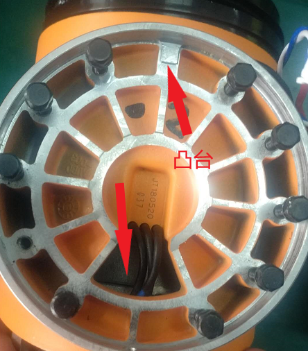 Figure 4-49 Routing the 14 module power wires and CAN wire (1)Figure 4-50 Routing the 14 module power wires and CAN wire (2)
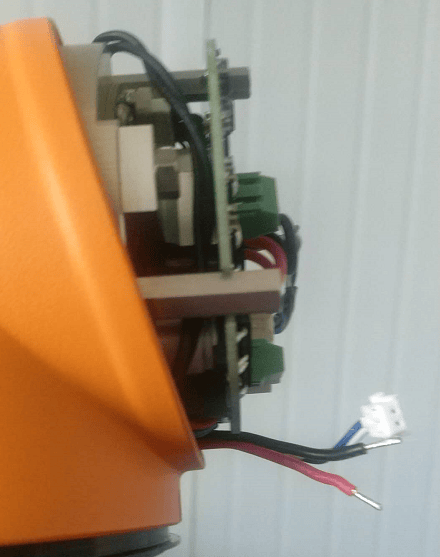 Figure 4-51 Pulling out the power wires and CAN wire at the PCB board
Insert the screws into their corresponding holes. Align the boss inside the joint with the groove of the forearm tube and keep the orientation consistent. Then drive the screws into the small holes and pre-tighten all ten screws. When pre-tightening, apply force to the joint to prevent it from loosening at the small holes. Finally, tighten the screws in a diagonal sequence using the size 5.5 open-end wrench.
Figure 4-52 Tightening the flange fixing screws of the 14 moduleUse the 2.5 mm hex key to reinstall the limit screw of joint 5.
Reinstall joint 6, which was removed earlier, in the same way.
Reconnect the 48V and GND power wires and the blue/white CAN terminals of joints 5 and 6 according to the records made during removal. Verify that the connections are properly seated and tightened and that the harness is not pinched, and refit the joint rear covers.
Return the decorative ring and the rubber ring to their original positions to complete the replacement of the 14 module.
4.3.7 Removing the 17 Module
This section uses the removal of joint 4 as an example to describe how to remove the 17 module.
Required Tools: size 5.5 open-end wrench for hex head screws, size 2.5 hex key, size 3 hex key, flat-head screwdriver, tweezers.
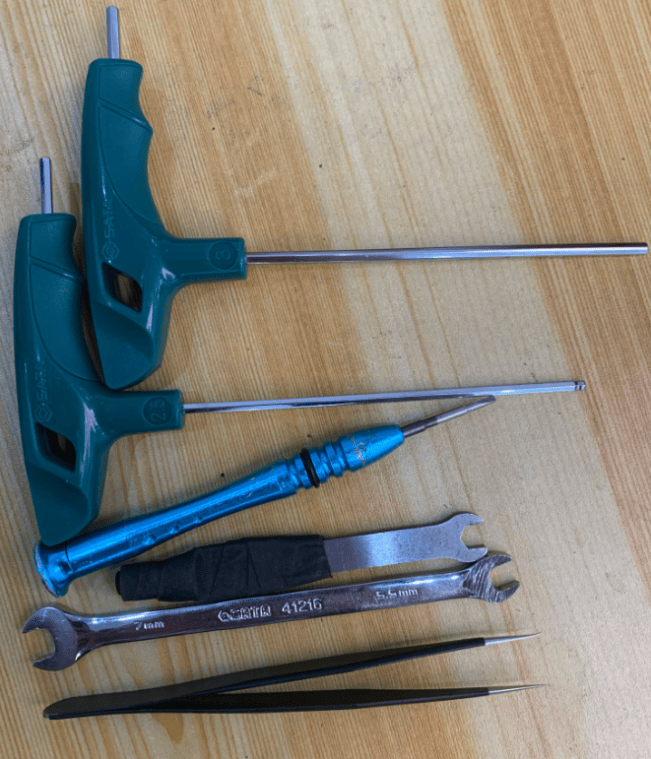
Procedure:
Use the 2.5 mm hex key to remove the three hexagon socket screws on the rear covers of joints 4 and 5.
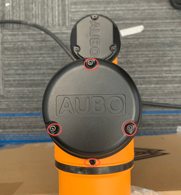 Figure 4-54 Removing the rear cover screws of joints 4 and 5
Unplug the blue/white CAN terminals of joints 4 and 5, and use a small flat-head screwdriver to disconnect the 48V and GND power wires.
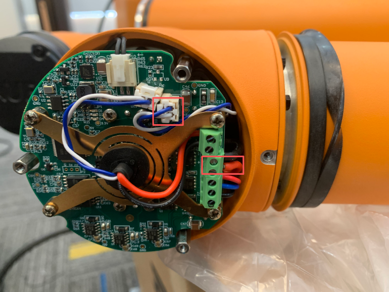 Figure 4-55 Disconnecting the CAN terminals of joints 4 and 5
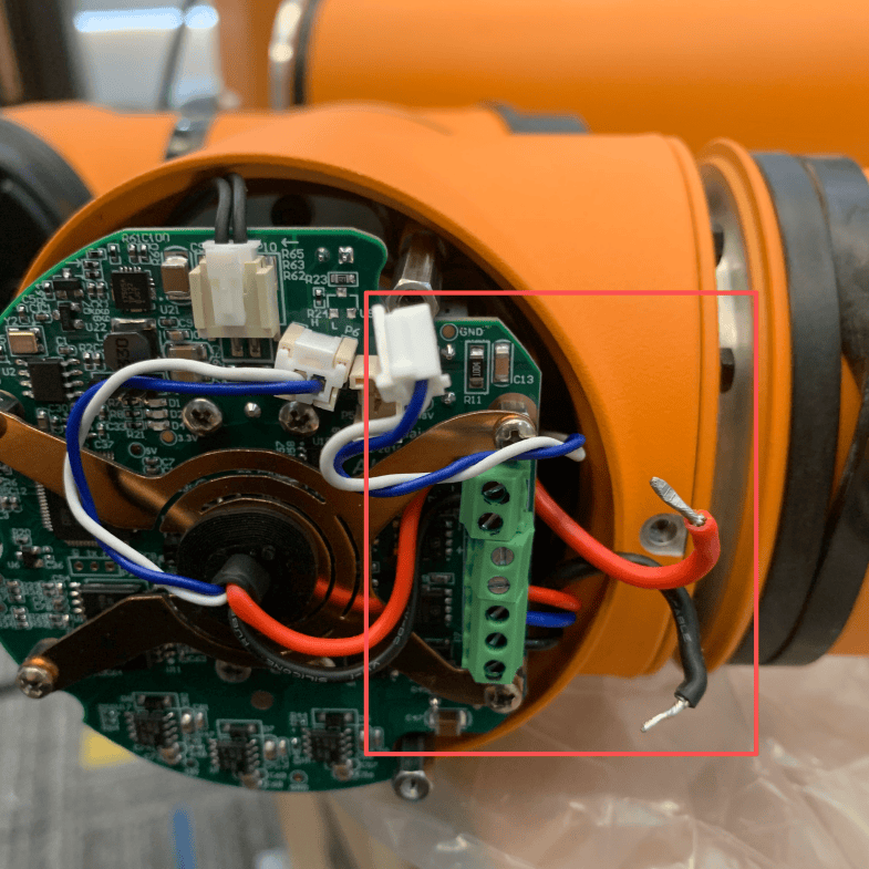 Figure 4-56 Disconnecting the power wires of joints 4 and 5
Fold the rubber ring at the joint connector back onto the joint, fold the rubber ring between joint 4 and the forearm tube back onto the joint, and retract the decorative ring to expose the fixing screws.
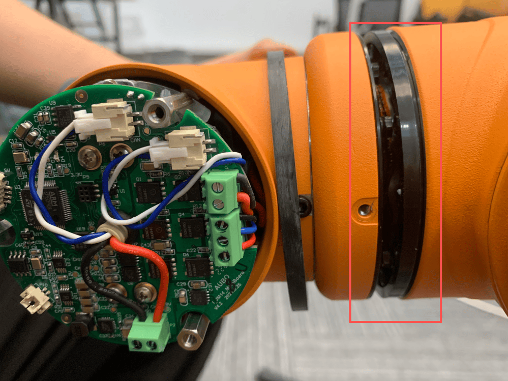 Figure 4-57 Retracting the decorative ring at the 17 module joint
Use the size 5.5 open-end wrench to loosen the ten flange fixing screws between joint 4 and the forearm tube until they are halfway out. Hold both ends of the joint with the left and right hands and rotate them in opposite directions until the mechanical stop is reached (the holes are keyhole-shaped). Then separate and remove joint 4 from the forearm tube. Pull gently during removal to avoid breaking the wires.
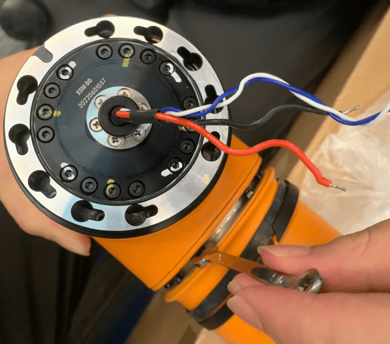 Figure 4-58 Loosening the flange fixing screws between joint 4 and the forearm tube
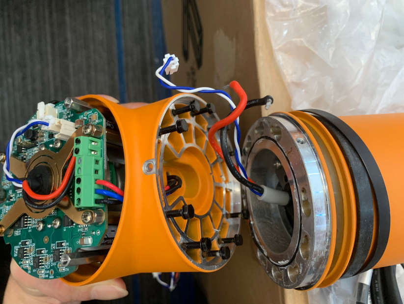 Figure 4-59 Separating joint 4 from the forearm tube
In the same way, use the size 5.5 open-end wrench to loosen the ten flange fixing screws between joints 4 and 5 until they are halfway out. Hold both ends of the joint with the left and right hands and rotate them in opposite directions until the mechanical stop is reached (the holes are keyhole-shaped). Then separate and remove joint 5 from joint 4. Pull gently during removal to avoid breaking the wires.
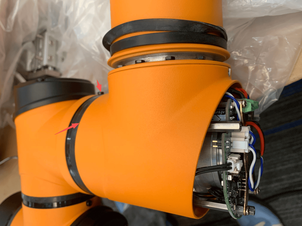 Figure 4-60 Loosening the flange fixing screws between joints 4 and 5
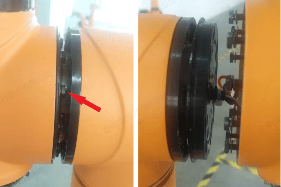 Figure 4-61 Separating joints 4 and 5 (1)
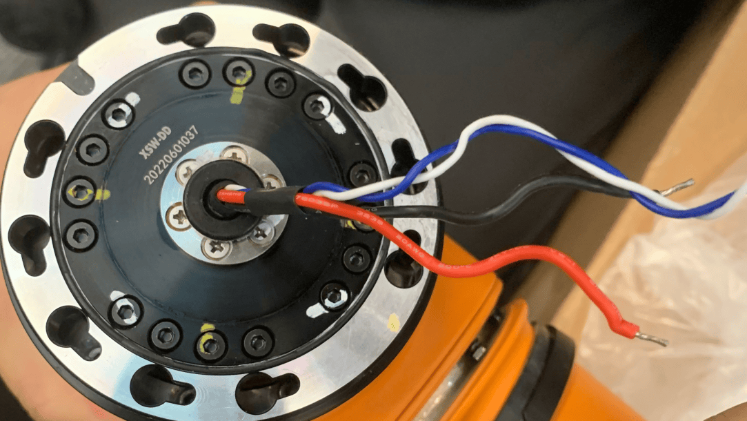 Figure 4-62 Separating joints 4 and 5 (2)
Once the joint 4 17 module has been separated from both the forearm tube and joint 5, the 17 module can be taken out.
4.3.8 Installing the 17 Module
Procedure:
Take a module with the same ID and specification. Before installation, verify that the sealing rubber rings on the flanges of joints 4 and 5 are seated in their grooves.
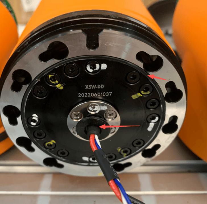 Figure 4-63 Checking the flange sealing ring of joint 4
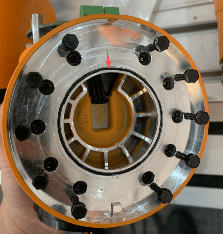 Figure 4-64 Checking the flange sealing ring of joint 5
Verify that the wires at the joint 5 flange are secured with cable ties.
Figure 4-65 Checking the wire securing condition at the joint 5 flangeReplace the ten screws on the joint with new screws (M3 × 14 mm), apply thread locker to the new screws, and leave the screws protruding by approximately 10 mm.
Feed the 48V and GND power wires and the blue/white CAN wire at the flange end of joint 4 through the gap in joint 5 into the joint, then use tweezers to take out the power wires and the blue/white CAN wire at the PCB board and pull them out by approximately 35 mm.
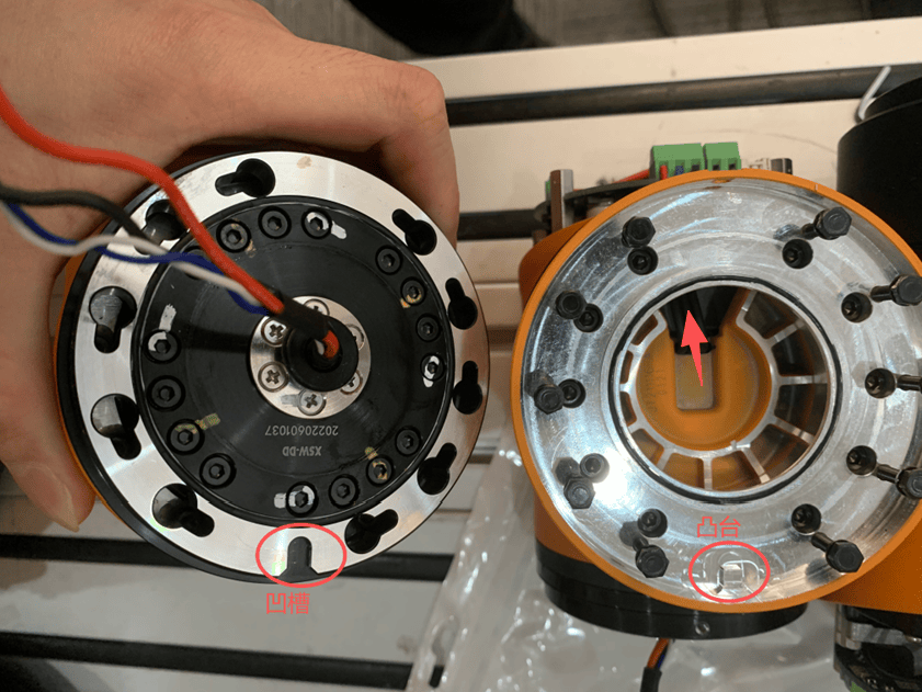 Figure 4-66 Routing the 17 module power wires and CAN wire (1)
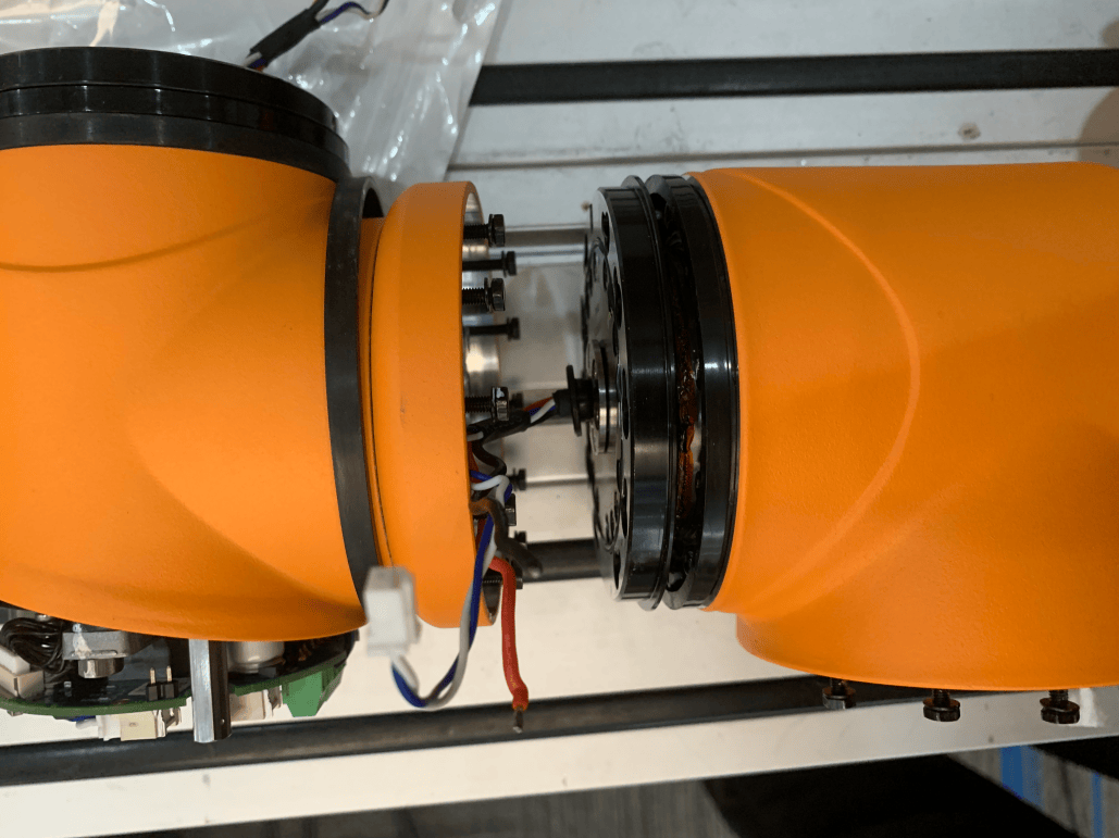 Figure 4-67 Routing the 17 module power wires and CAN wire (2)Figure 4-68 Pulling out the power wires and CAN wire at the PCB board
Insert the screws into their corresponding holes. Align the boss inside the joint with the groove of the forearm tube and keep the orientation consistent. Then drive the screws into the small holes and pre-tighten all ten screws. When pre-tightening, apply force to the joint to prevent it from loosening at the small holes. Finally, tighten the screws in a diagonal sequence using the size 5.5 open-end wrench.
Figure 4-69 Tightening the flange fixing screws of the 17 moduleUse the 2.5 mm hex key to reinstall the limit screw of joint 5.
Reinstall the forearm tube, which was removed earlier, in the same way.
Reconnect the 48V and GND power wires and the blue/white CAN terminals of joints 4 and 5 according to the records made during removal. Verify that the connections are properly seated and tightened and that the harness is not pinched, and refit the joint rear covers.
Return the decorative ring and the rubber ring to their original positions to complete the replacement of the 17 module.
4.3.9 Removing the 25 Module
This section uses the removal of joint 3 as an example to describe how to remove the 25 module.
Required Tools: size 7 open-end wrench for hex head screws, size 2.5 hex key, size 3 hex key, Phillips screwdriver, tweezers.
Procedure:
Use the size 2.5 hex key to unscrew the four screws on the rear cover of the 25 module to be removed, and take off the rear cover.
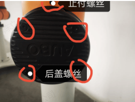 Figure 4-70 Screw positions on the 25 module rear cover
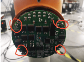 Figure 4-71 Before unscrewing the 25 module rear cover screws
Use a Phillips screwdriver to unscrew the screws of the 25 module main control board and gently lift the main control board to expose the connection wires between the 25 module and the upper arm tube (black/red power wires, yellow/green CAN wire, blue/white CAN wire).
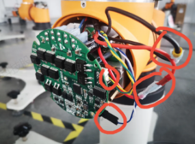 Figure 4-72 Lifting the 25 module main control board
Disconnect and unplug the connection wires between the 25 module and the upper arm tube (black/red power wires, yellow/green CAN wire, blue/white CAN wire).
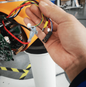 Figure 4-73 Disconnecting the wires between the 25 module and the upper arm tube
Locate the decorative ring at the joint between the 25 module and the upper arm tube. Use the size 2.5 hex key to unscrew the screw inside the decorative ring and remove the decorative ring.
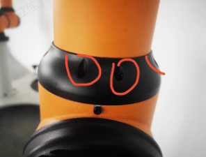 Figure 4-74 Removing the screw of the 25 module decorative ring
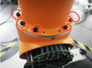 Figure 4-75 Removal of the 25 module decorative ring complete
After the decorative ring has been removed, the ten size 3 screws connecting the 25 module and the upper arm tube are exposed. Use the size 3 hex key to remove these ten screws.
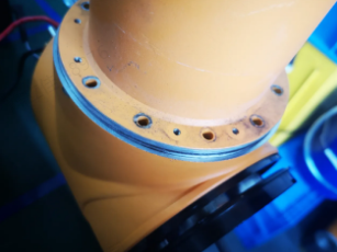 Figure 4-76 Removing the screws connecting the 25 module and the upper arm tube
Gently pull out the upper arm tube and pull the central lead wires of the upper arm tube (black/red power wires, yellow/green CAN wire, blue/white CAN wire) out through the boss hole of the 25 module.
CAUTION
Pull the central lead wires gently to avoid damaging them.
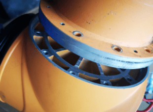 Figure 4-77 Pulling out the upper arm tube central lead wires (1)
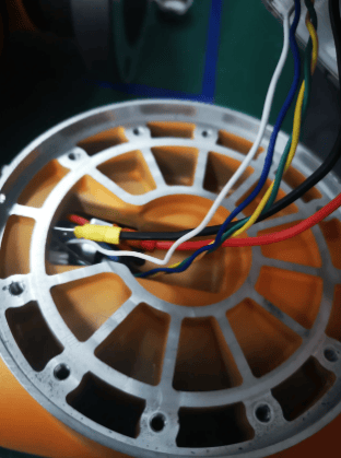 Figure 4-78 Pulling out the upper arm tube central lead wires (2)
The connection between the joint 3 25 module and the upper arm tube has now been removed.
Before removing the elbow tube between joint 3 and the forearm tube, first locate the rubber ring at the joint between the elbow tube and joint 3.
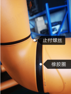 Figure 4-79 Locating the rubber ring at the elbow tube joint
Use tweezers to pull out the rubber ring and move it aside.
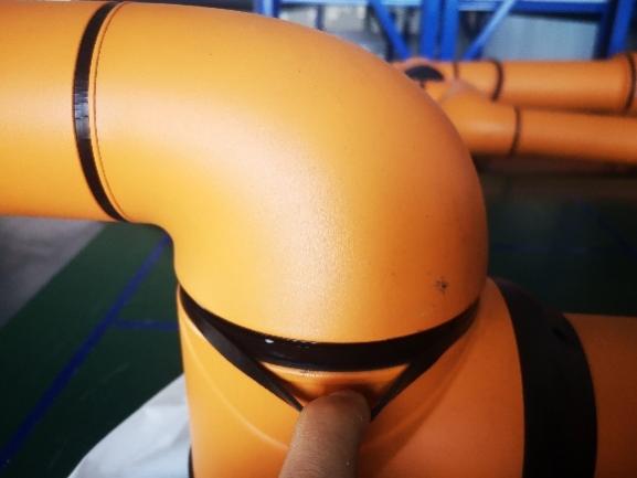 Figure 4-80 Pulling out the rubber ring at the elbow tube joint (1)
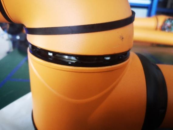 Figure 4-81 Pulling out the rubber ring at the elbow tube joint (2)
Open the dust ring aside to expose the inner circle of ten hex head screws (4 × 18 mm).
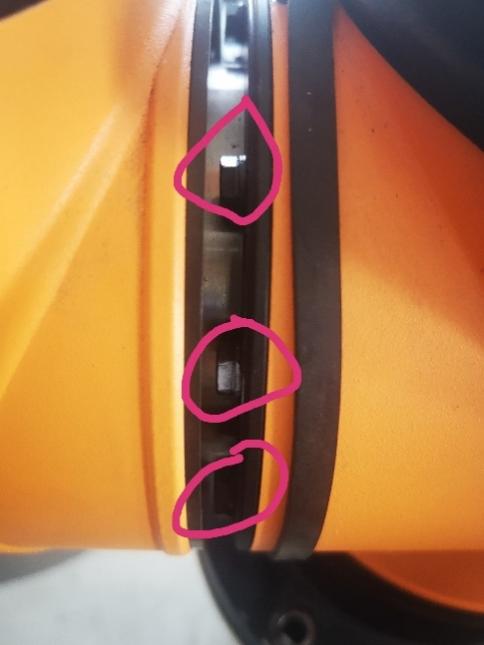
- Use the size 7 open-end wrench to loosen the hex head screws one by one by approximately 8 mm.
CAUTION
Avoid stripping the screw threads when loosening the screws. The use of a torque wrench is recommended.
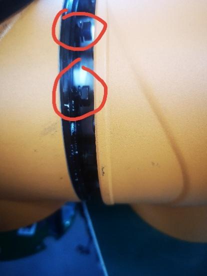
- Once all ten screws in the circle have been loosened, rotate the elbow tube counterclockwise with both hands until it reaches the position of the large notch where the flange engages with the screws.
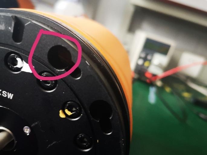
- Gently pull out the elbow tube and disconnect the wires between the elbow tube and joint 3 (black/red power wires, blue/white CAN wire).
CAUTION
Pull the connection wires gently to avoid breaking them.
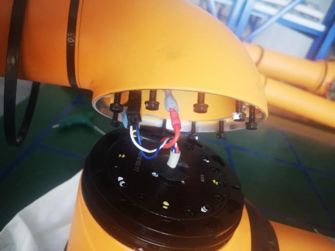
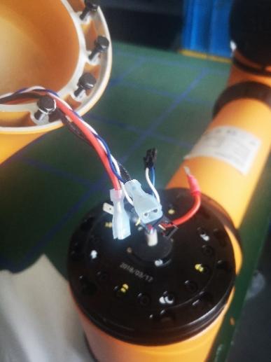
- Once the elbow tube has been removed, the joint 3 25 module is disconnected from both the elbow tube and the upper arm tube. The 25 module can now be taken out to complete the removal.
4.3.10 Installing the 25 Module
Procedure:
Insert the central lead wires of the upper arm tube through the boss hole of the joint 3 25 module, and insert the upper arm tube gently.
CAUTION
Insert the central lead wires gently to avoid damaging them.
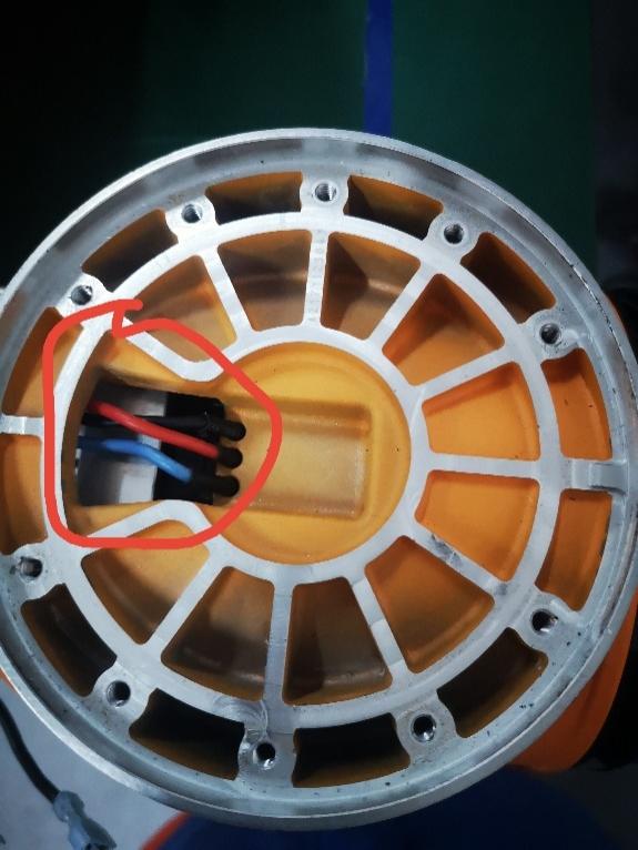 Figure 4-87 Inserting the upper arm tube central lead wires (1)
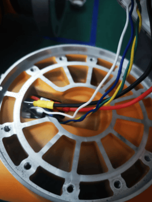 Figure 4-88 Inserting the upper arm tube central lead wires (2)
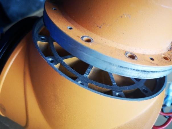 Figure 4-89 Inserting the upper arm tube
During installation, verify that the boss of the joint 3 25 module engages with the groove of the upper arm tube.
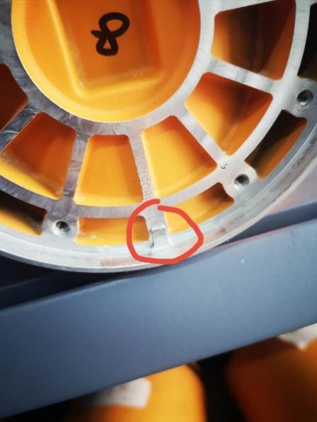 Figure 4-90 Aligning the boss of the joint 3 25 module with the upper arm tube groove (1)
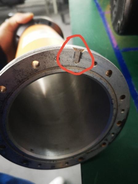 Figure 4-91 Aligning the boss of the joint 3 25 module with the upper arm tube groove (2)
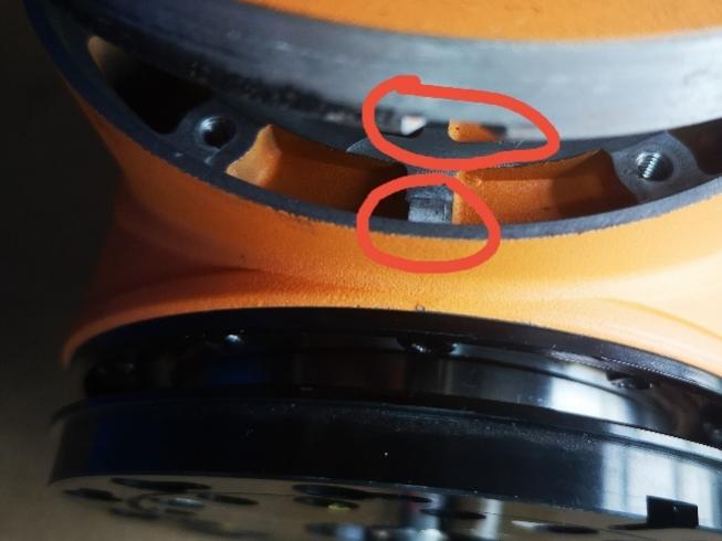 Figure 4-92 Aligning the boss of the joint 3 25 module with the upper arm tube groove (3)
Screw in the ten size 3 screws to secure the 25 module to the upper arm tube.
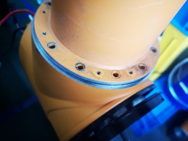 Figure 4-93 Installing the screws connecting the 25 module and the upper arm tube (1)
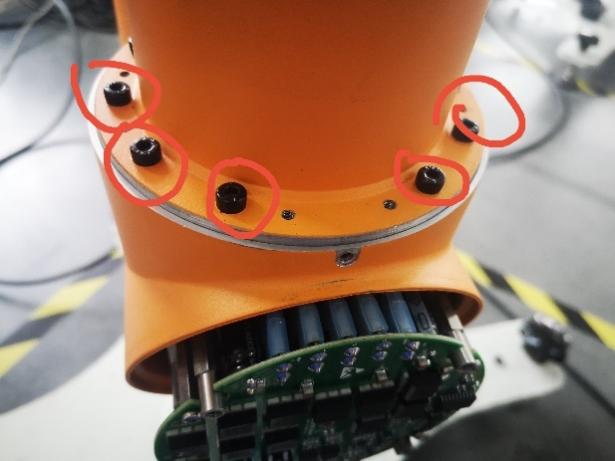 Figure 4-94 Installing the screws connecting the 25 module and the upper arm tube (2)
Refit the decorative ring and tighten the screw inside the decorative ring with the size 2.5 hex key.
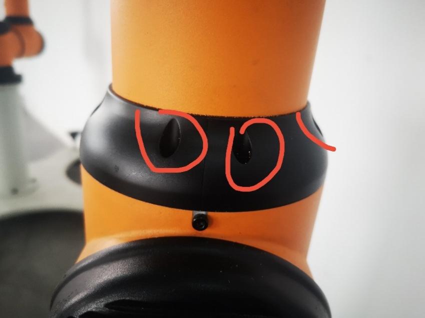 Figure 4-95 Installing the 25 module decorative ring
Connect the wires between the joint 3 25 module and the upper arm tube (black/red power wires, yellow/green CAN wire, blue/white CAN wire).
 Figure 4-96 Connecting the cables of the 25 module and the upper arm tube (1)
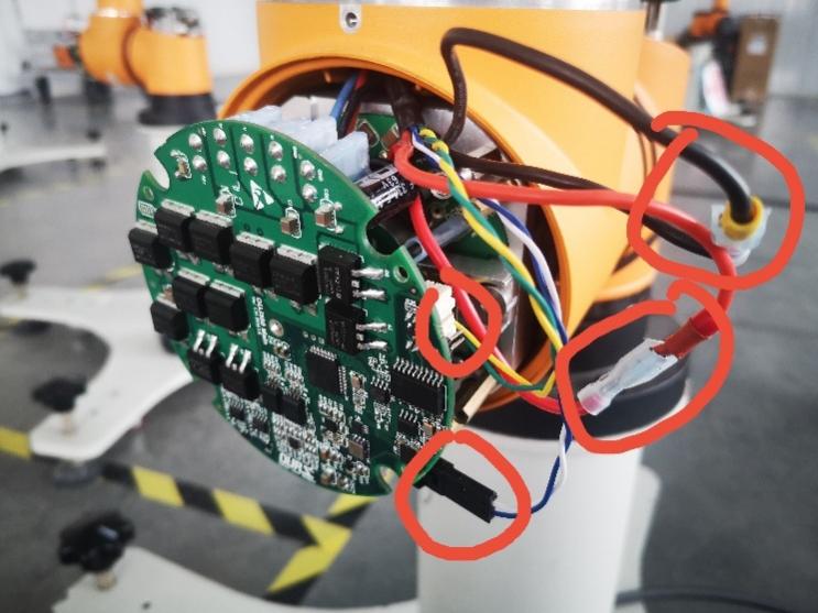 Figure 4-97 Connecting the cables of the 25 module and the upper arm tube (2)
Gently close the main control board and tighten the four Phillips screws.
CAUTION
When closing the main control board, route the connection wires (black/red power wires, yellow/green CAN wire, blue/white CAN wire) properly beneath the main control board to avoid crushing them.
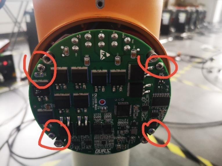 Figure 4-98 Closing the 25 module main control board
Close the rear cover and use the size 2.5 hex key to screw in the four rear cover screws of the 25 module and the arm tube set screw.
CAUTION
Avoid pinching the connection wires when installing the rear cover.
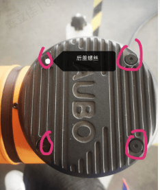 Figure 4-99 Installing the 25 module rear cover
The installation of the joint 3 25 module and the upper arm tube is now complete.
Insert the connection wires between the elbow tube and the joint 3 25 module (black/red power wires, blue/white CAN wire).
CAUTION
Insert the connection wires gently to avoid breaking them.
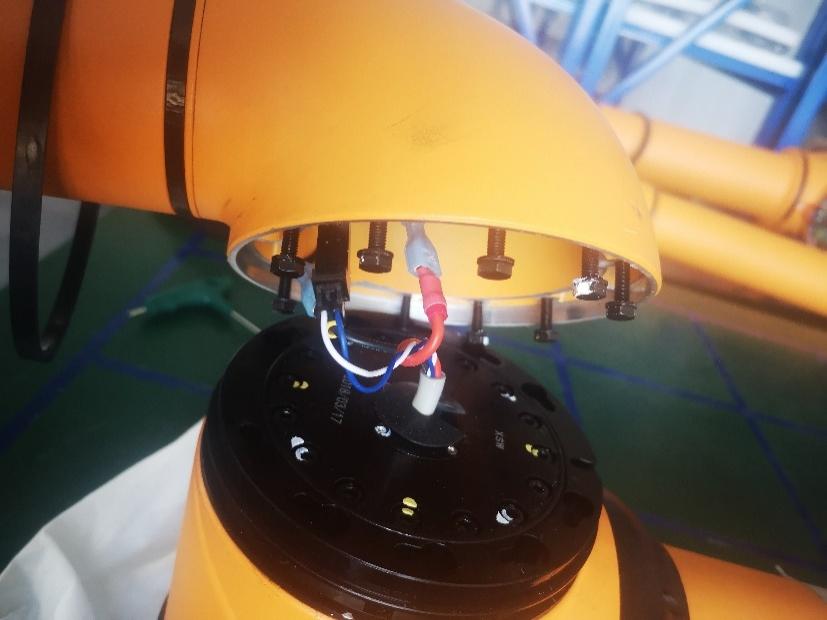 Figure 4-100 Connecting the cables of the elbow tube and the 25 module
Insert the elbow tube screws into the large notches of the screw holes on the flange of the 25 module. The ten hex head screws (4 × 18 mm) around the circle must be replaced with new screws with thread locker applied, and screwed in until the screw head is approximately 18 mm from the base platform.
Rotate the base clockwise to bring the screws to the position of the small notch where the 25 module engages with the flange, and tighten the hex head screws one by one using the size 7 open-end wrench.
CAUTION
Avoid stripping the screw threads when tightening.
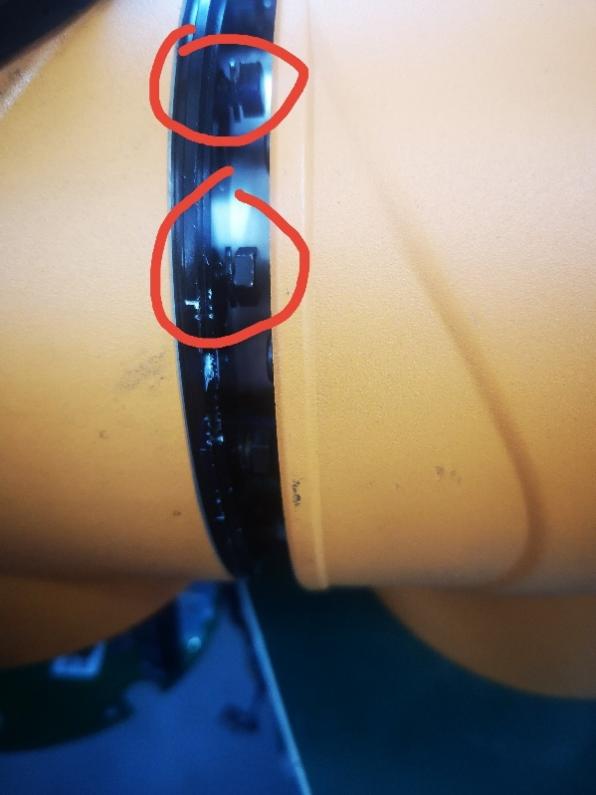
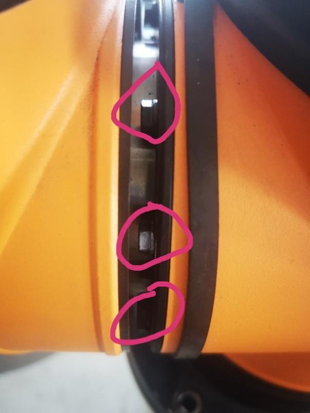
- After the screws have been tightened, lower the dust ring into place.
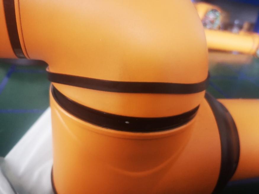
- Place the rubber ring inside the dust ring and screw in the set screw. The replacement and installation of the joint 3 25 module is now complete.
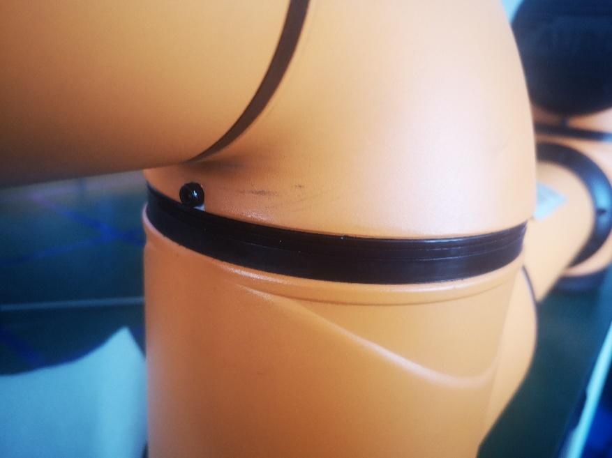
4.3.11 Removing the 32 Module
Required Tools: size 7 open-end wrench for hex head screws, size 2.5 hex key, Phillips screwdriver, tweezers.
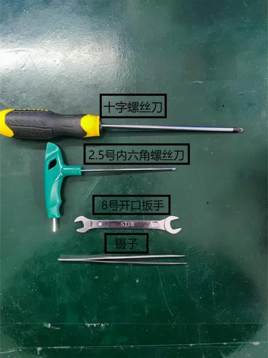
Procedure:
Use the size 2.5 hex key to unscrew the four rear cover screws and the set screw of module 1, and take off the rear cover.
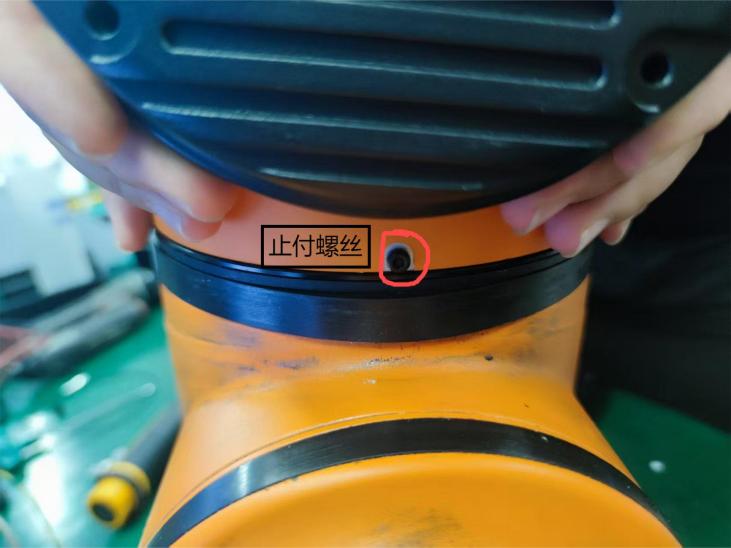 Figure 4-106 Before unscrewing the module 1 rear cover screws
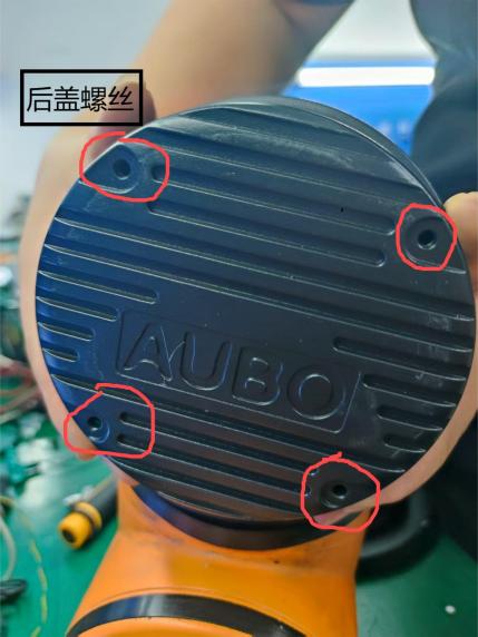 Figure 4-107 Before unscrewing the module 1 set screw
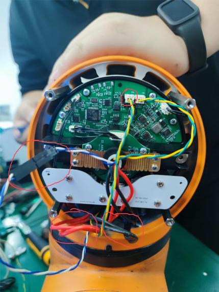 Figure 4-108 After unscrewing the module 1 rear cover screws
Use a Phillips screwdriver to unscrew the screws inside the rear cover of module 1 to expose the connection wires between modules 1 and 2 (black/red power wires, yellow/green CAN wire, blue/white CAN wire).
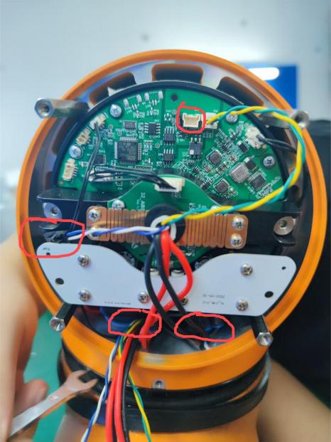 Figure 4-109 Connection wires between modules 1 and 2 exposed
Disconnect and unplug the connection wires between modules 1 and 2 (black/red power wires, yellow/green CAN wire, blue/white CAN wire).
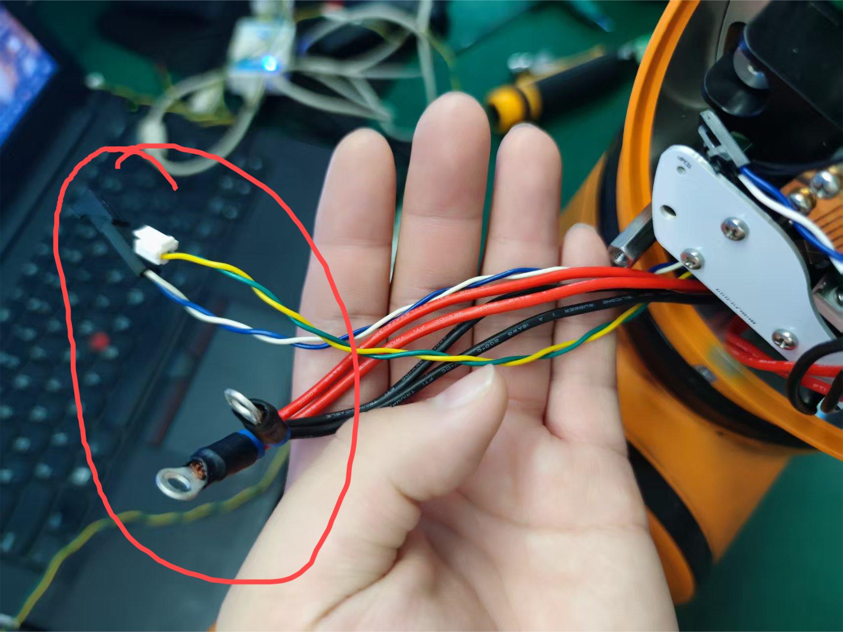 Figure 4-110 Disconnecting the wires between modules 1 and 2
Locate the rubber ring at the joint between modules 1 and 2.
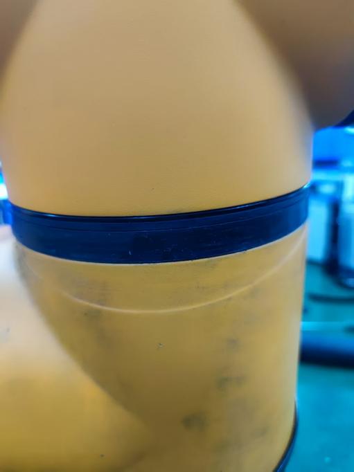 Figure 4-111 Locating the rubber ring at the joint between modules 1 and 2
Use tweezers to pry out the rubber ring and move it aside.
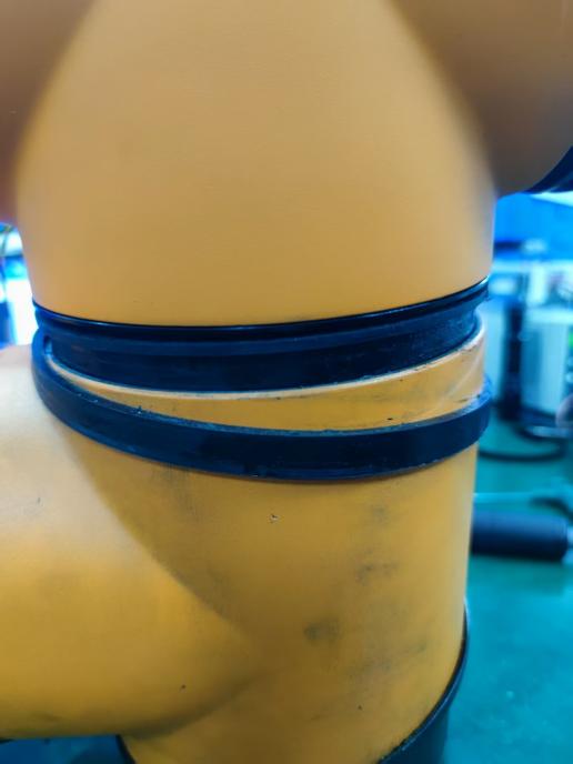 Figure 4-112 Prying out the 32 module rubber ring
Open the dust ring aside to expose the inner circle of ten hex head screws (4 × 18 mm).
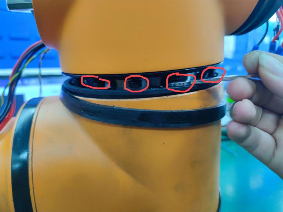 Figure 4-113 Opening the 32 module dust ring
Use the size 7 open-end wrench to loosen the hex head screws one by one by approximately 8 mm.
CAUTION
Avoid stripping the screw threads when loosening the screws.
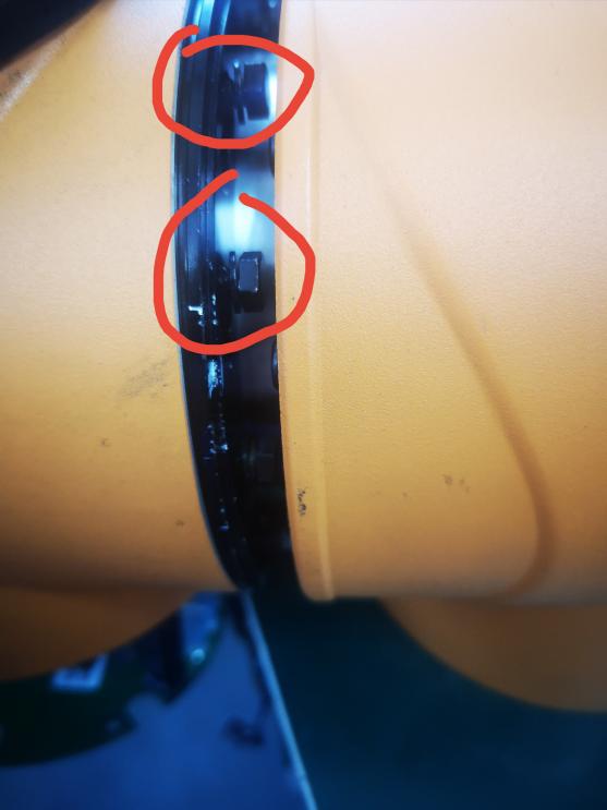 Figure 4-114 Loosening the 32 module hex head screws
Once all ten screws in the circle have been loosened, rotate module 1 counterclockwise with both hands until it reaches the position of the large notch where the flange engages with the screws.
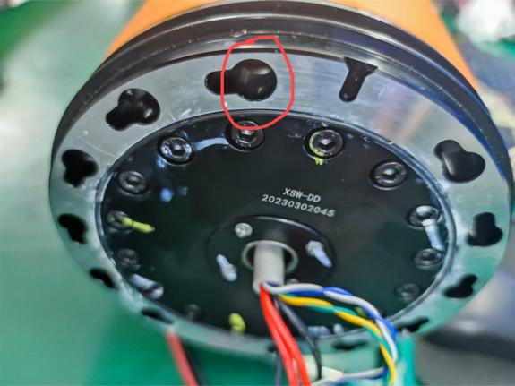 Figure 4-115 Rotating module 1 to the large notch position
Gently pull out module 1 and unplug the connection wires between the modules (black/red power wires, yellow/green CAN wire, blue/white CAN wire).
CAUTION
Pull the connection wires gently to avoid breaking them.
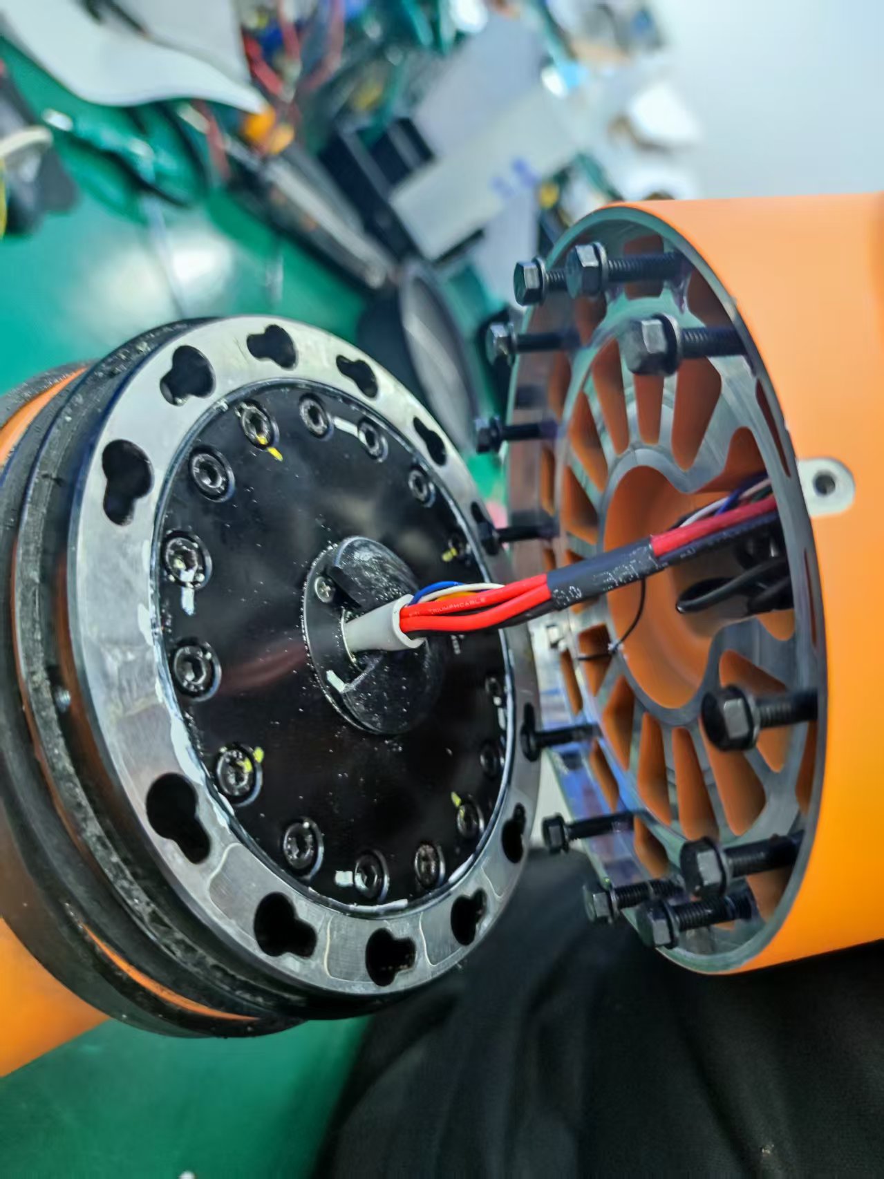 Figure 4-116 Pulling out the 32 module central lead wires
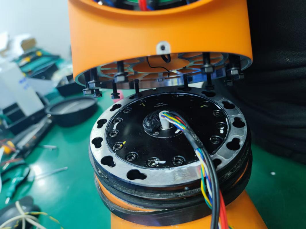 Figure 4-117 Removal of the 32 module complete
The removal of module 1 is now complete.
4.3.12 Installing the 32 Module
Procedure:
Insert the central lead wires of module 2 through the boss hole of module 1 into module 1, and pull out the central lead wires.
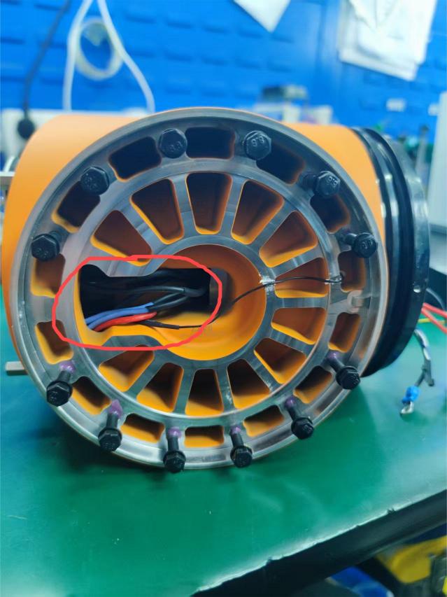 Figure 4-118 Inserting the 32 module central lead wires (1)
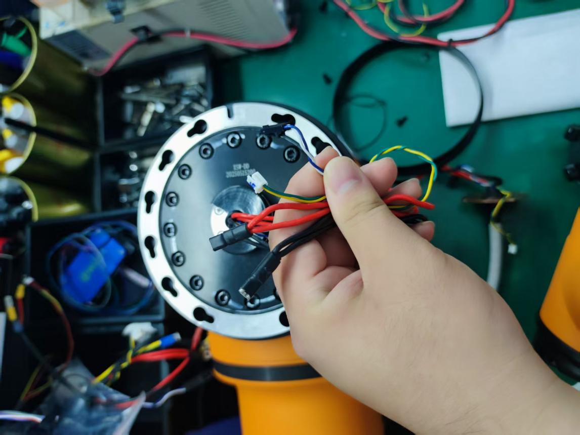 Figure 4-119 Inserting the 32 module central lead wires (2)Figure 4-120 Pulling out the 32 module central lead wires
Insert the module 1 screws into the large notches of the screw holes on the flange of module 2.
CAUTION
The central lead wires of module 1 must be pulled out to prevent them from being crushed, and the sealing ring must not be omitted.
The ten hex head screws (4 × 18 mm) around the circle must be replaced with new screws with thread locker applied, and screwed in until the screw head is approximately 18 mm from the base platform.
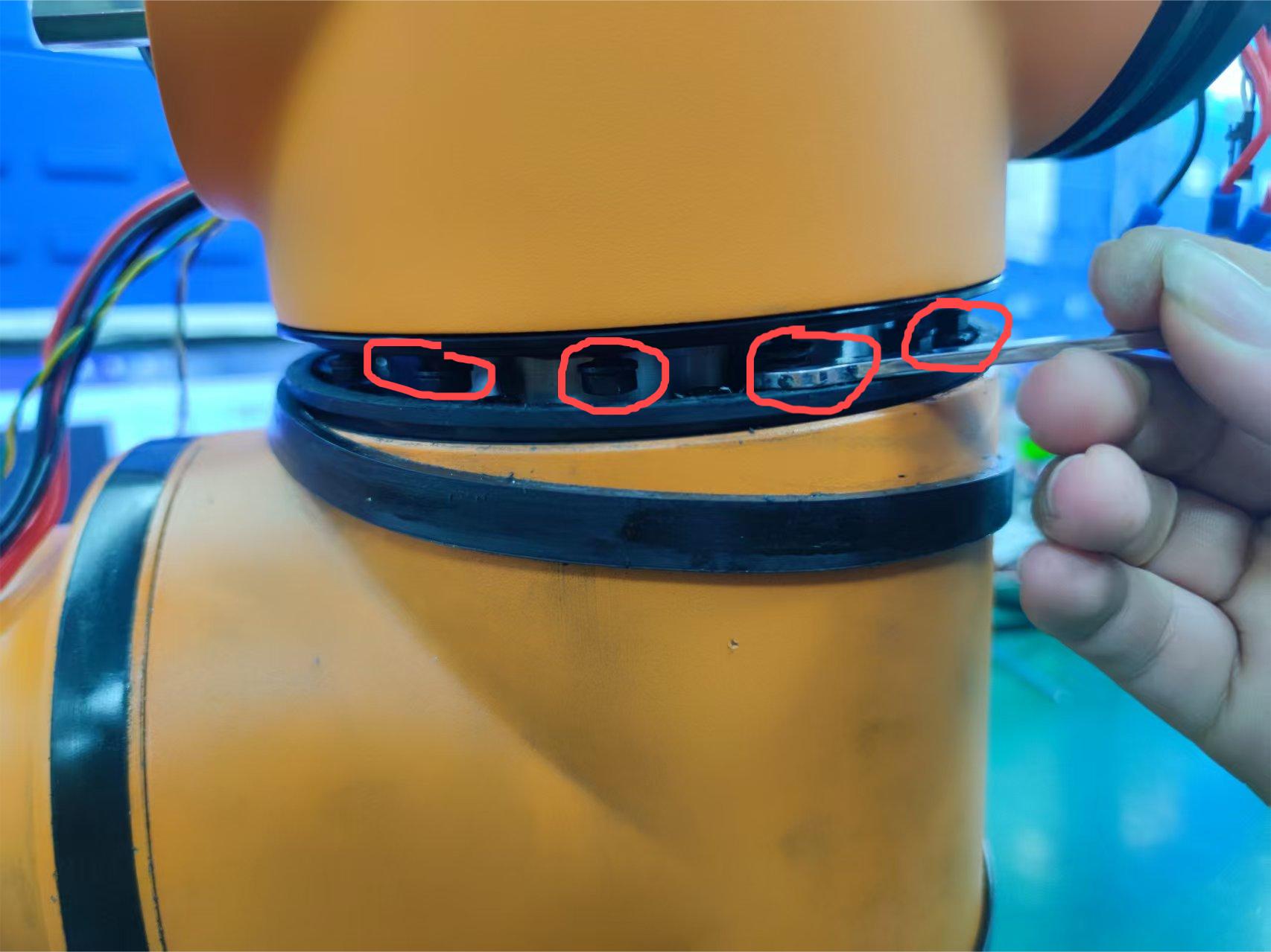 Figure 4-121 Inserting the module 1 screws into the large notch position
When inserting, make sure that the boss of module 1 engages with the notch on the flange of module 2.
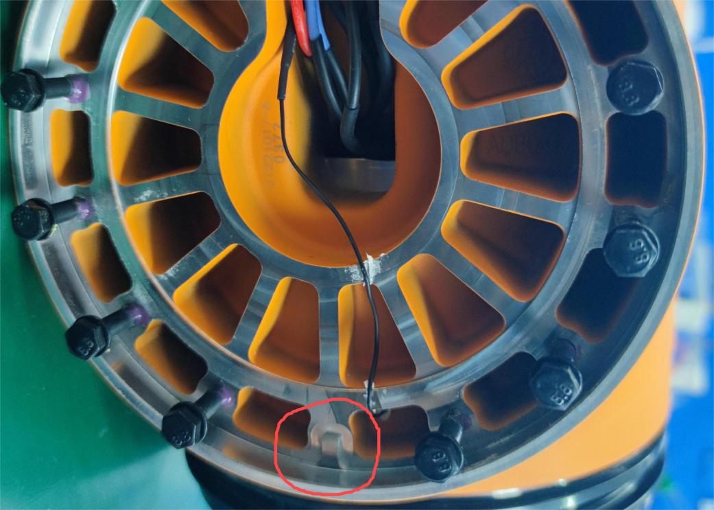 Figure 4-122 Aligning the module 1 boss with the module 2 flange notch (1)
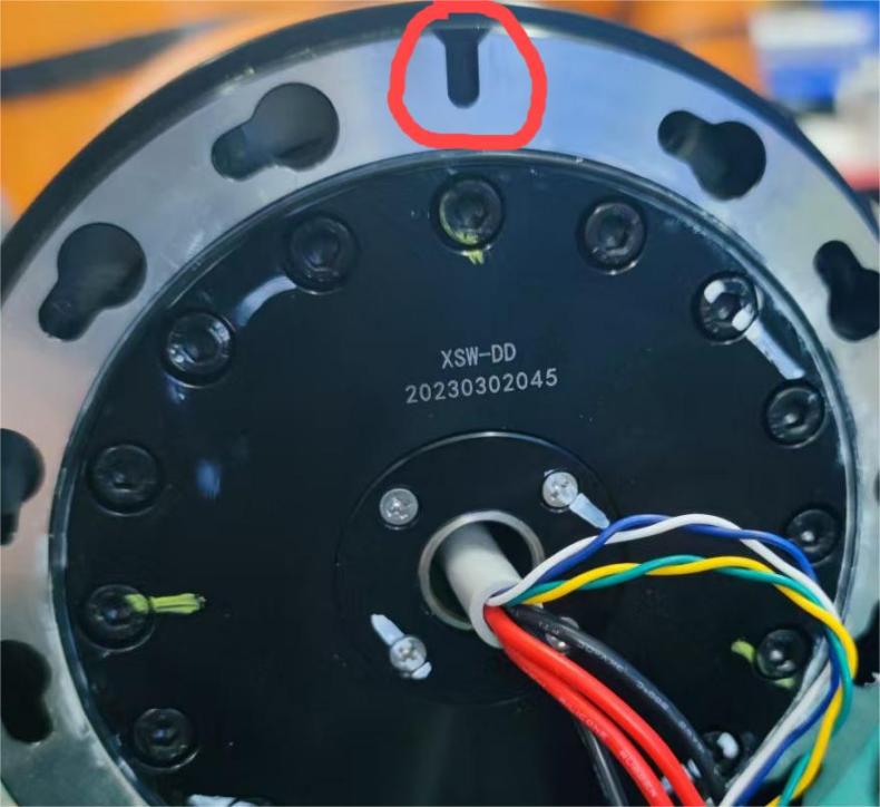 Figure 4-123 Aligning the module 1 boss with the module 2 flange notch (2)
Rotate module 1 clockwise to bring the screws to the position of the small notch where module 2 engages with the flange, and tighten the hex head screws one by one using the size 7 open-end wrench.
CAUTION
Avoid stripping the screw threads when tightening.
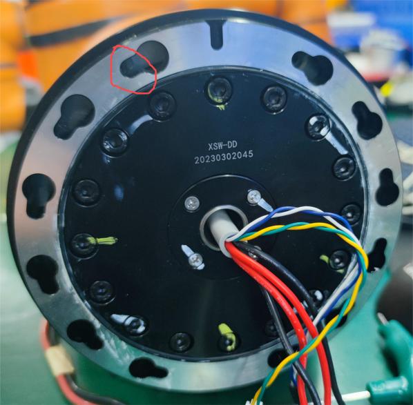 Figure 4-124 Tightening the 32 module hex head screwsFigure 4-125 Screw installation positions on the 32 module
After the screws have been tightened, lower the dust ring into place.
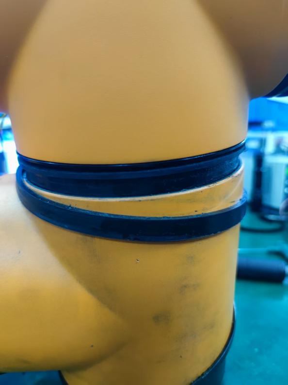 Figure 4-126 Restoring the 32 module dust ring
Place the rubber ring inside the dust ring.
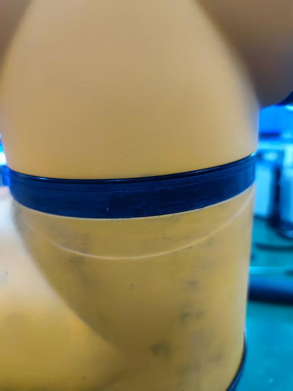 Figure 4-127 Restoring the 32 module rubber ring
Connect the connection wires of module 1.
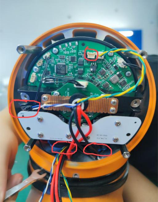 Figure 4-128 Connection position of the module 1 wiresFigure 4-129 Before connecting the module 1 wires
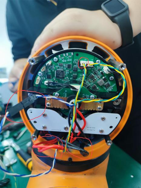 Figure 4-130 After connecting the module 1 wires
Close the rear cover and use the size 2.5 hex key to screw in the four rear cover screws of the module and the module 1 set screw.
CAUTION
Avoid pinching the connection wires when installing the rear cover.
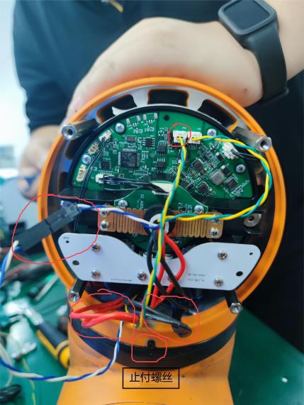 Figure 4-131 Before closing the 32 module rear coverFigure 4-132 Installing the 32 module rear cover screwsFigure 4-133 Installing the 32 module set screw
Verify that the rear cover screws, set screw, rubber ring, and dust ring are all correctly installed to complete the installation of the 32 module.
4.3.13 Post-Replacement Inspection and Return to Operation
After replacing the end effector or a joint module, perform the following checks before returning the equipment to operation:
- Verify that the model, specification, and ID of the replacement part match the equipment requirements.
- Verify that all connectors, power wires, and CAN wires have been restored according to the removal records, that they are properly seated and tightened, and that the harness is routed correctly and is not pinched.
- Verify that the fixing screws, limit screws, rear covers, decorative rings, rubber rings, and dust rings are all correctly installed, and that tools and foreign objects have been removed.
- After restoring the power supply, check the equipment status, joint positions, and alarm messages. If zero-position, encoder, ID, or firmware configuration is required for the corresponding model, complete it according to the official product documentation or the procedure confirmed by the after-sales service team.
- After clearing the workspace and verifying that the safety functions operate normally, first perform a low-speed test run with no payload. Normal operation may be resumed only after confirming that there are no alarms, abnormal noises, interference, or abnormal motion.
5 Basic Software Operation Guide
5.1 Viewing Version Information
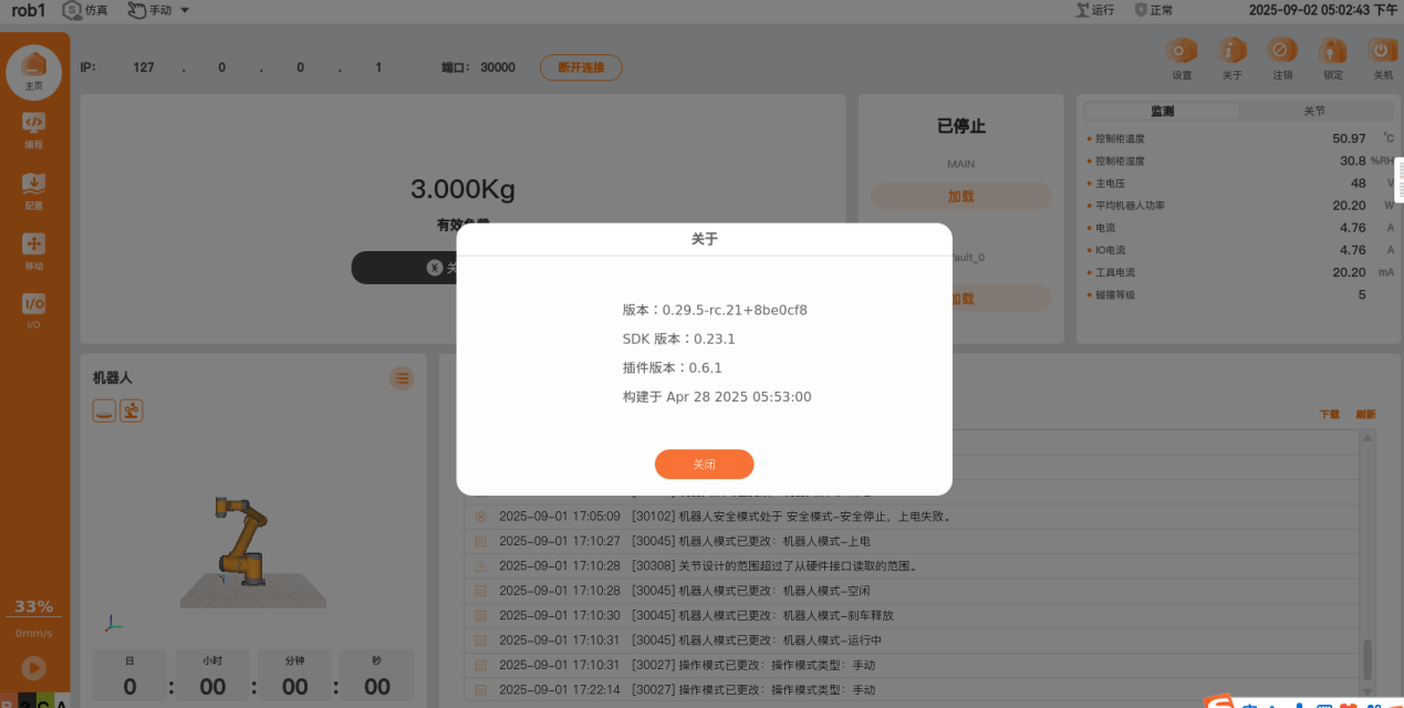
Version information is usually required for problem analysis when the equipment fails. You can open the About page from the upper right corner of the software home page to view the software version, OEM version, SDK version, plug-in version, build time, copyright information, and company website, as shown in Figure 5-1.
5.2 Upgrading the Software and Firmware
Both the software version and the firmware version of the ARCS system support version upgrades. Before upgrading, verify that the update package comes from a reliable source and that the version matches the equipment model, and select the offline or online upgrade method according to the on-site conditions.
Preparations Before Upgrading:
- Identify the current ARCS software version and firmware version, and record the version information before upgrading.
- Prepare the software or firmware upgrade package of the target version, and verify that the files are complete and come from a reliable source.
- Back up programs, logs, and any data that must be retained on site.
- Verify that the robot is in a safe state and that there are no unsaved operations or running tasks on site.
- For an offline upgrade, prepare a USB flash drive formatted as FAT32 or exFAT, and avoid using special characters in the drive name.
- For an online upgrade, verify that the controller is connected to a network with Internet access.
Upgrade Methods:
- Offline upgrade: Copy the software or firmware upgrade package to a USB flash drive and install the version using the USB import and software upgrade functions in the system settings.
- Online upgrade: If the controller has Internet access, download and install the target version using the software upgrade function in the system settings.
Confirmation After Upgrading:
- Complete the shutdown or restart as prompted by the system.
- After the restart, check the software version or firmware version information again.
- Verify that the current version matches the target upgrade version.
- Check that the robot powers up normally and that communication and basic operations work correctly.
For more detailed procedures, refer to: ARCS Software and Firmware Upgrade Guide.
5.3 Exporting ARCS System Logs and Importing Programs
The ARCS system supports exporting logs to a USB flash drive and re-importing existing backup programs into the controller. Before performing a version upgrade, equipment maintenance, or controller replacement, complete a program backup according to the corresponding product documentation and verify that the backup files are usable. Before importing programs, verify that the backup files come from a reliable source and keep the current data.
Preparations:
- Prepare a USB flash drive and verify that it is recognized correctly by the controller or the teach pendant.
- Verify that the program files to be imported come from a reliable source and have a complete file structure.
- Before importing programs, verify that the existing programs and logs in the current controller have been backed up.
- When programs will be replaced, verify that the on-site equipment is in a safe state, and avoid overwriting program files that still need to be retained.
5.3.1 Notes on Log Export, Backup, and Viewing
Before maintenance, replacement, or troubleshooting, it is recommended to export and back up the logs so that they are available for subsequent problem analysis and data traceability. When the equipment fails, log files are normally required for problem analysis; these can be found under the corresponding paths according to the log type.
Log Export Procedure:
After verifying that the robot arm has stopped moving, insert the USB flash drive into the USB port of the teach pendant or the controller, and click the download button in the log area at the lower right corner of the ARCS software home page, as shown in Figure 5-2.
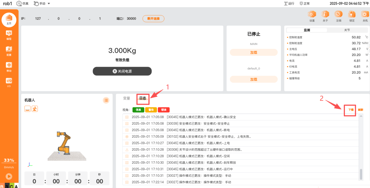 Figure 5-2 Software home page
In the log download dialog box that appears, select the inserted USB flash drive and click Select, as shown in Figure 5-3.
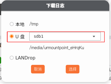 Figure 5-3 Log download dialog box
Wait until the log export is complete and click Exit to finish the log export, as shown in Figure 5-4.
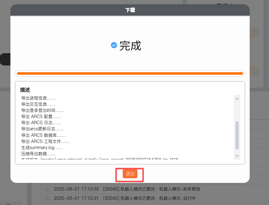 Figure 5-4 Log download complete
Log Path Description:
| Log type | Storage path | Description |
|---|---|---|
| Control log | /root/arcs_ws/log/aubo_control.log | Logs related to the control functions. |
| Scope log | /root/arcs_ws/log/aubo_scope.log | Logs related to Scope. |
| Webscope backend log | /root/arcs_ws/log/webscope/backend.log | Logs of the Webscope backend service. |
| Crash log | /root/arcs_ws/log/.crash/ | Crash logs include a time stamp, which can be used to identify the time of the crash. |
| Operation log | /root/arcs_ws/log/.trace/ | Logs related to the operation trace. |
| Diagnostic data file | /root/arcs_ws/log/.trace/rob1_timestamp.csv | Diagnostic data file, which can be used for further analysis of the equipment status. |
Inspection Requirements:
After the log export is complete, verify that the corresponding log files have been created on the USB flash drive and store the backup files properly. To view logs locally on the equipment, verify that the required log path exists and that the file time matches the time at which the fault occurred.
5.3.2 Importing Programs
A program can be imported in either of two ways: by replacing the program folder or a specific program in the controller backend file system, or by copying the program to be restored to a USB flash drive and importing it through the system import function.
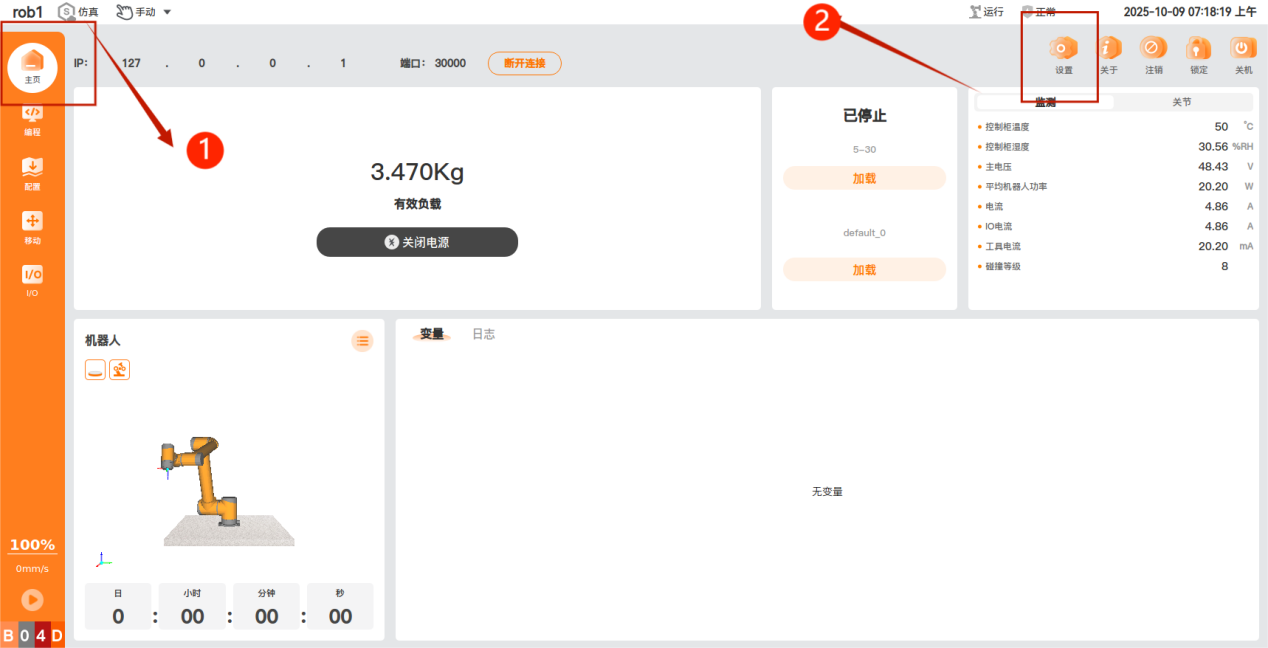
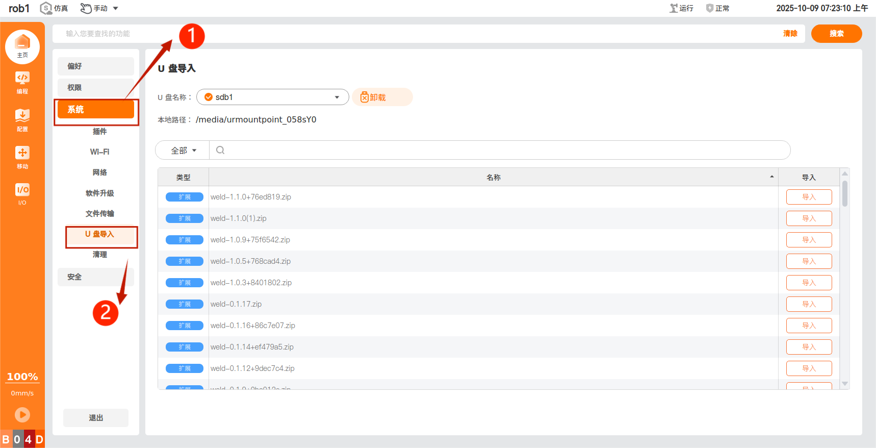
In the AuboStudio software, click "Home > Settings > System > USB Import" in sequence to open the USB import screen.
As shown in Figures 5-5 and 5-6.
Method 1: Restoring a Program Through the Backend File System
Locate the backup file on the USB import page, select the backup file to be imported, and click Import.
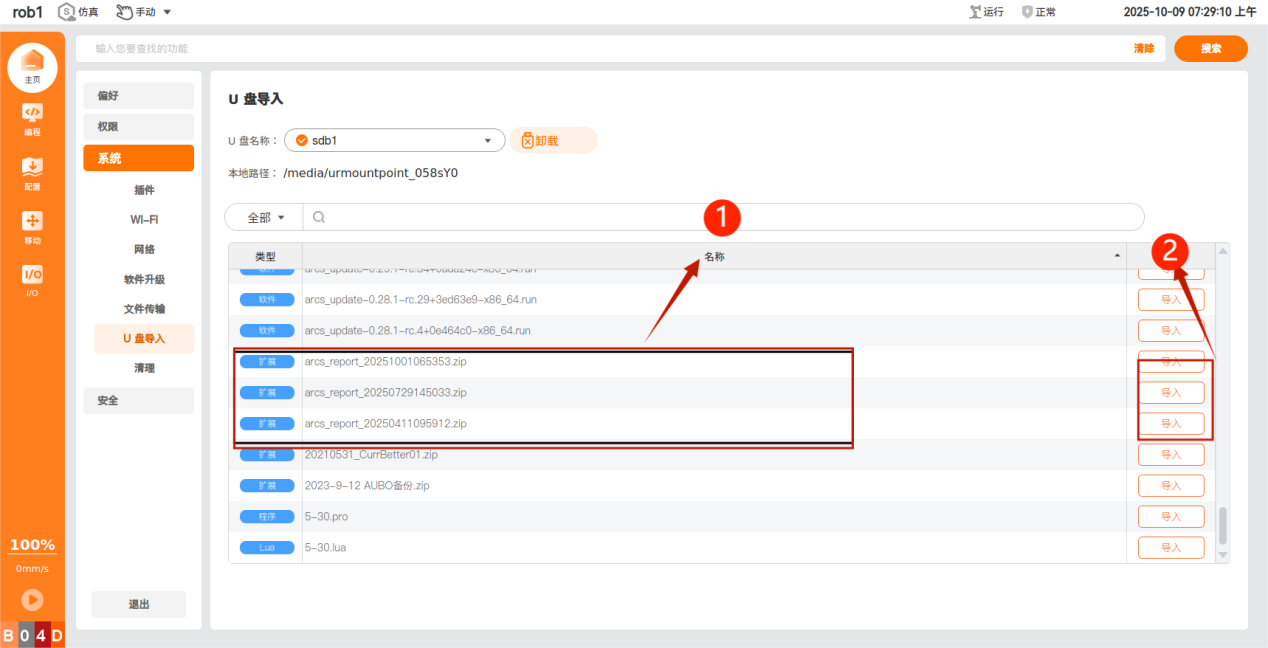 Figure 5-7 Selecting the backup file
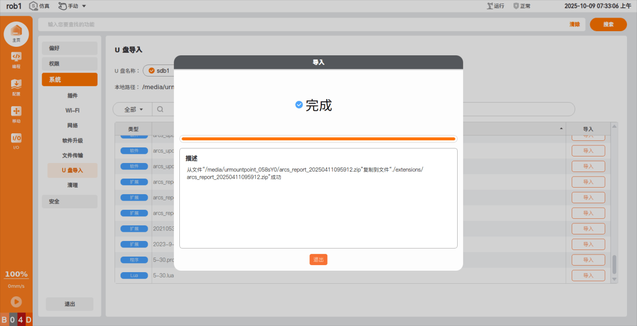 Figure 5-8 Backup file import complete
After the import is complete, return to the home page and click Log Out to switch to the backend system.
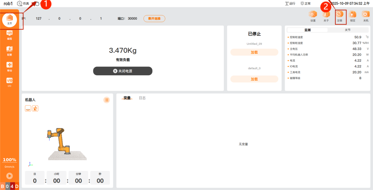 Figure 5-9 Logging out and switching to the backend
Click
root, then locate and open theARCS_WSfolder.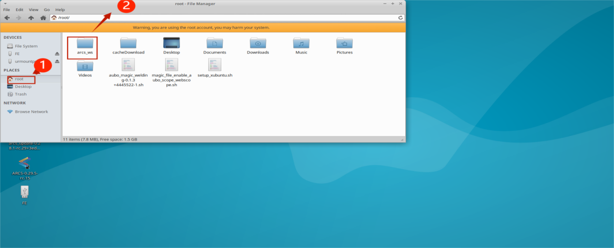 Figure 5-10 Opening the ARCS_WS folder
Locate the imported backup file in
ARCS_WSand extract it.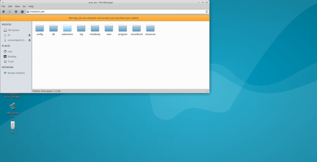 Figure 5-11 Extracting the backup file (1)
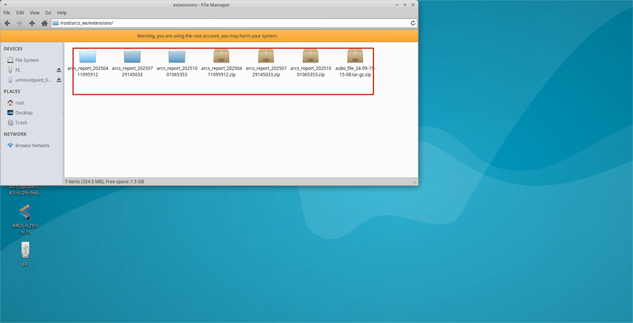 Figure 5-12 Extracting the backup file (2)
Open the extracted folder and locate the
programfolder. You can either copy the entireprogramfolder, or open theprogramfolder and copy only the individual program to be restored.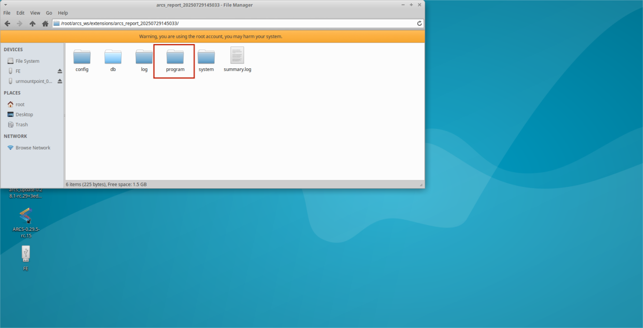 Figure 5-13 Copying the program folder or a specified program
Return to the
ARCS_WSfolder underrootand replace the entireprogramfolder with the copied one, or paste the individual program into the existingprogramfolder.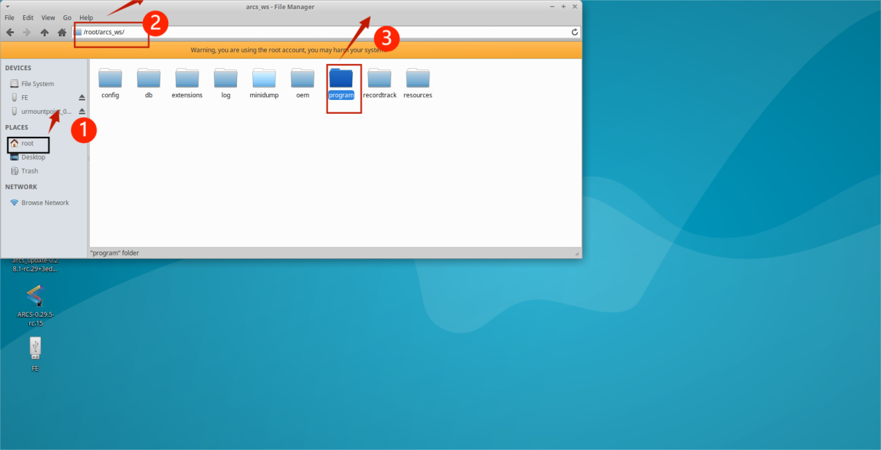 Figure 5-14 Replacing or pasting the program files
Method 2: Importing Program Files from a USB Flash Drive
In the backup file, locate the
programfolder and copy the programs to be imported.Paste the copied programs onto the USB flash drive.
 Figure 5-15 Copying programs to the USB flash drive (1)
 Figure 5-16 Copying programs to the USB flash drive (2)
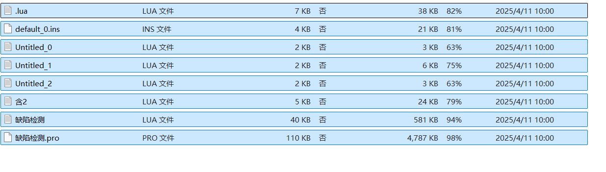 Figure 5-17 Copying programs to the USB flash drive (3)
Return to the USB Import page in the system.
Figure 5-18 Returning to the USB import pageLocate the program files on the USB flash drive, select the programs to be imported, and perform the import.
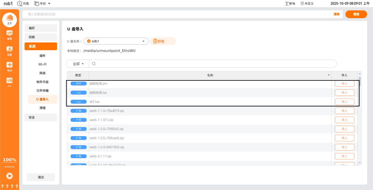 Figure 5-19 Importing program files from the USB flash drive
Post-Import Inspection:
- Verify that the target program appears in the controller program list or in the
programfolder. - Before opening a program, check that the program name, number of files, and path are as expected.
- If an existing program has been replaced, verify that the original program has been backed up and check that the replaced program opens correctly.
- Before running a program, first verify that the robot, fixtures, end-of-arm tooling, and site environment are in a safe state.
5.4 Connecting to the Controller Remotely via VNC
VNC can be used to display and control the teach pendant interface remotely from a computer, which is convenient for viewing the equipment status remotely, assisting with commissioning, and performing basic operations.
Preparations Before Use:
- Prepare a computer, a network cable, and the AUBO robotic equipment to be connected.
- Verify that the controller and the computer are on the same network and that the computer can access the controller IP address.
- Verify that the VNC service is installed and enabled on the controller.
- Install a VNC client such as VNC Viewer on the computer.
- Verify that the ARCS system software version on the equipment meets the requirements for using VNC.
Connection Points:
- Create a new connection in the VNC client and enter the controller IP address and VNC port according to the on-site configuration. The port is normally
5900. - Enter the connection name and login password according to the on-site configuration.
- Once the connection is established, the current teach pendant interface can be viewed and controlled from the computer.
Usage Notes:
- Before performing any remote operation, verify that the robot on site is in a safe state and maintain communication with on-site personnel.
- Avoid performing unconfirmed remote operations while the robot is running or while on-site personnel are carrying out maintenance.
- After use, it is recommended to disconnect the VNC remote connection.
For more detailed procedures, refer to: Connecting to the Controller Remotely via VNC.
5.5 Connecting to the Controller Remotely via SSH Using MobaXTerm
SSH can be used to log in to the controller system remotely from a computer, in order to check the equipment status, transfer files, and perform necessary maintenance operations. This section uses MobaXTerm as an example to describe the applicable scenarios and preparations.
Preparations Before Use:
- Prepare a computer, a network cable, and the AUBO robotic equipment to be connected.
- Verify that the computer and the controller are on the same network segment and that the computer can access the controller IP address.
- Enable SSH access on the controller or teach pendant system, and confirm the SSH port and authentication method.
- Install MobaXTerm or another SSH-capable client tool on the computer.
- Make sure you have the authentication information required to log in to the controller, such as the account name, password, or key file.
Connection Methods:
- Password authentication login: Log in using the controller IP address, SSH port, user name, and password. This method is suitable for basic connections and initial configuration scenarios.
- Key authentication login: Generate a public key and a private key first, configure the public key on the controller, and then log in using the private key. This method is suitable for remote access scenarios with higher security requirements.
Usage Notes:
- After logging in via SSH, you can access the controller file system. Confirm the file path and purpose of the operation before proceeding.
- Do not arbitrarily delete, move, or overwrite system files, to avoid affecting normal controller operation.
- Keep the key files secure and never disclose the private key.
- After use, it is recommended to disconnect the SSH session.
For more detailed procedures, refer to: Using MobaXTerm to Connect to the Controller Remotely via SSH.
6 Troubleshooting
This chapter guides maintenance personnel in making preliminary assessments and handling problems relating to the robot, controller, teach pendant, communication network, and common application integration issues. Troubleshooting shall follow the principle of "safety first, then diagnosis; external first, then internal; record first, then act." If a fault involves safety functions, brakes, joint droop, abnormal motion, electrical disassembly, or hardware replacement, stop the equipment immediately and contact the AUBO after-sales service team.
6.1 General Troubleshooting Principles
- Confirm the safe state: Before entering the robot workspace, verify that the robot has stopped moving, and implement safety measures appropriate to the on-site risk, such as emergency stop, power isolation, and lockout/tagout.
- Confirm personnel qualifications: Live measurements, controller disassembly and reassembly, cable modification, brake release, joint module replacement, and return-to-factory packing shall be performed by trained maintenance personnel.
- Record information first: Before taking action, record the time at which the fault occurred, the alarm content, the alarm code, the most recent operations, the software version, the robot model, the controller model, and the status of the on-site power supply and external equipment.
- Diagnose systematically: Work through the checks step by step in the following order: power supply, cables, connectors, earthing, network, parameters, software version, peripherals, hardware components.
- Verify one factor at a time: Adjust only one parameter, cable, or component at a time, then retest and record the result. Randomly replacing multiple components makes it impossible to trace the root cause.
- Never bypass safety functions: If safety or collision-related settings have been temporarily adjusted for troubleshooting purposes, restore the original safety settings and re-verify the safety functions once the fault has been resolved.
6.2 General Diagnostic Procedure
| Step | Inspection item | Requirement |
|---|---|---|
| 1 | Confirm the safe state | Stop the program and verify that the robot cannot move unexpectedly; if necessary, perform an emergency stop, power isolation, or lockout/tagout. |
| 2 | Record fault information | Record the alarm code, alarm text, time of occurrence, the motion in progress, whether the fault is reproducible, and take photos or video on site. |
| 3 | Determine the scenario | Establish whether the fault appeared after new installation, maintenance, an upgrade, or relocation, or whether it occurred suddenly during normal operation. |
| 4 | Inspect appearance and connections | Inspect the robot arm cables, teach pendant cable, controller wiring, earthing, connectors, screws, and any external damage. |
| 5 | Check the power supply and voltage | Check the input power supply, controller power indicators, the 24 V / 48 V supply, fuses, and power module status. |
| 6 | Check software and parameters | Check the robot model, controller model, software version, firmware version, payload, tool, network, and fieldbus parameters. |
| 7 | Isolate by section | Verify each section in turn: controller, robot arm, teach pendant, external devices, network devices, PLC, or vision system. |
| 8 | Retest and archive | After the fault has been resolved, retest the operation, safety functions, and alarm status, and record the handling process and final result. |
| Fault scenario | Priority inspection items |
|---|---|
| After new installation | Power supply specification, earthing, robot arm cables, teach pendant cable, controller configuration, network address, installation posture, and external safety wiring. |
| After maintenance or component replacement | Replacement part model, connector seating, harness routing, screw tightening, spare part version, maintenance records, and re-verification of safety functions. |
| After a software or firmware upgrade | Host software version, joint/interface board firmware version, plug-in compatibility, project file compatibility, and whether the EDS/GSD files and slave address table have been updated accordingly. |
| After relocation or modification | On-site power supply, network topology, wiring of peripherals such as PLC / vision systems / grippers, IP addresses, fixture positions, payload and tool parameters. |
| Sudden occurrence during operation | Alarm code, motion path, payload status, collision records, log events, power supply fluctuations, external safety signals, and fieldbus communication quality. |
If the on-site alarm text does not exactly match the descriptions in this chapter, the alarm code, logs, and actual equipment status displayed by the teach pendant software shall take precedence.
6.3 Power-On, Power Supply, and Start-Up Faults
Symptom: The controller cannot be powered on site
- Possible causes: The on-site input voltage or frequency does not match the rated controller input; the 110 V / 220 V supply setting has not been verified; a fault in the power cable, switch, fuse, or internal power module.
- Diagnostic procedure:
- Verify that the on-site supply voltage, frequency, earthing, and power capacity meet the requirements on the controller nameplate.
- If the site is supplied with 110 V AC, de-energize the equipment and verify that the internal power selector or input setting of the controller is configured as required by the equipment.
- Check the power cable, plug, circuit breaker, emergency stop circuit, and the controller power switch status.
- Observe the status of the controller power, standby, and robot indicators to determine whether the fault lies in the external supply or in the internal power supply chain of the controller.
- Recommended action: Adjust the supply configuration according to the equipment rated input and the on-site supply conditions, then power on again. Checks involving the controller internal power selector, fuses, or power modules shall be performed by trained personnel with the equipment de-energized.
- When to contact after-sales or technical support: If the input supply is normal but the controller shows no indication at all, trips repeatedly, or emits an unusual odor or shows signs of burning, stop attempting to power on and contact the after-sales service team.
Symptom: Start-up stops at the selection screen or the system fails to load
- Possible causes: Abnormal system boot, low charge in the RTC battery on the main control board, storage or system file errors, external boot devices affecting the boot sequence.
- Diagnostic procedure:
- Disconnect all non-essential USB devices, external keyboards and mice, and removable storage devices, then restart.
- If a maintenance screen must be accessed, log in according to the on-site account management requirements or the instructions of the after-sales service team.
- Check whether the system time has been lost. If the system time is incorrect, check the RTC battery voltage during the annual maintenance.
- Record the screen at which start-up stops, the error message, and the system version.
- Recommended action: Access the system using an external keyboard first, following the instructions of the after-sales service team. If the RTC battery is found to be low, replace the battery during the annual maintenance and confirm the system time again.
- When to contact after-sales or technical support: If the system repeatedly fails to start, file system errors occur, or the maintenance account cannot be used to log in, export the on-site information and contact the after-sales service team.
Symptom: Power-on fails due to joint overtravel, power-on timeout, or an incorrect joint current position
- Possible causes: A joint is outside its limit, abnormal robot arm cable connection, an incorrect current position caused by the robot being moved by external force after power-off, or an abnormal brake status.
- Diagnostic procedure:
- Check whether the cable between the robot arm and the controller is fully seated and whether the connector is damaged or loose.
- Check the status of each joint on the jogging or diagnostics screen, and identify any joint that is over its limit or whose current position is abnormal.
- If a joint has exceeded its limit, rotate it back into the permitted range while ensuring that this can be done safely.
- If the brake must be released or the joint rear cover opened, this shall be done by trained personnel after the equipment has been de-energized and mechanically supported.
- Recommended action: Clear the loose cable connections and the joint overtravel condition, then power on again. For a joint whose brake has been released, verify that the posture is stable and free from any risk of droop before resuming operation.
- When to contact after-sales or technical support: If the same joint position error is reported repeatedly after several power-on attempts, if the joint cannot move, or if there is a risk of droop, contact the after-sales service team.
Symptom: Joint undervoltage, Hall error, encoder error, or absolute encoder error
- Possible causes: A fault in the joint encoder, Hall sensor, joint drive, power supply chain, or joint communication.
- Diagnostic procedure:
- Record the complete alarm code, the number of the affected joint, and the motion in progress at the time of the alarm.
- Check whether the robot arm cable and the connection at the controller end are secure.
- Observe whether the fault always occurs on the same joint and whether it appears immediately during power-on.
- Do not disassemble joint encoders or drive components on site without authorization.
- Recommended action: Alarms of this type normally require further hardware diagnostics. After identifying the faulty joint, follow the after-sales instructions to move the robot arm to a safe posture and prepare it for return to factory or on-site repair.
- When to contact after-sales or technical support: If repeated alarms occur relating to the encoder, Hall sensor, absolute encoder, or joint undervoltage, stop operation and contact the after-sales service team.
6.4 Teach Pendant Display, Touch, and Screen Calibration Faults
Symptom: The teach pendant shows a black screen or no display after power-on
- Possible causes: Loose teach pendant cable, abnormal display harness, insufficient memory in the industrial computer, or a fault in the internal display chain of the controller or in the LVDS harness.
- Diagnostic procedure:
- Check the teach pendant cable, the connector at the controller end, and the power status.
- Try restarting the controller and observe whether the black screen recurs consistently.
- If conditions permit, carry out a cross-swap test with a spare teach pendant or a spare controller. Before each disconnection or reconnection, switch off the controller and disconnect the mains supply; power on again for testing only after the connections have been restored and the enclosure is fully reassembled.
- If the cross-swap test isolates the fault to the teach pendant, inspect the internal cables of the teach pendant. If it isolates the fault to the controller, inspect the display harness of the controller.
- Recommended action: Reseat any loose cables; free up system resources or replace/expand the memory if memory is insufficient; replace the relevant harness if the display harness is faulty.
- When to contact after-sales or technical support: If the black screen is accompanied by signs of burning, unusual odor, failure to start, or if the cross-swap test isolates the fault to a hardware defect, contact the after-sales service team.
Symptom: Teach pendant touch failure, local dead zones, or a horizontally mirrored display
- Possible causes: Touch screen calibration error, touch screen hardware fault, abnormal teach pendant cable, or abnormal host software or communication component version.
- Diagnostic procedure:
- Check whether the system time continues to run normally when the touch function fails.
- If the system time runs normally, check the touch screen, the teach pendant cable, and the hardware connections first.
- If the system time has stopped or the interface has frozen, record the software version and check the versions of the host software and communication components.
- For local touch dead zones or a horizontally mirrored display, verify that the robot arm has stopped moving, then connect an external mouse, open the screen calibration screen, and calibrate again. The calibration entry is located at "Home > Settings > Preferences > Teach Pendant" on the teach software home page; click Enable Touch Calibration. The screen layout is shown in Figure 6-1; for detailed steps, refer to Preference Settings — Other.
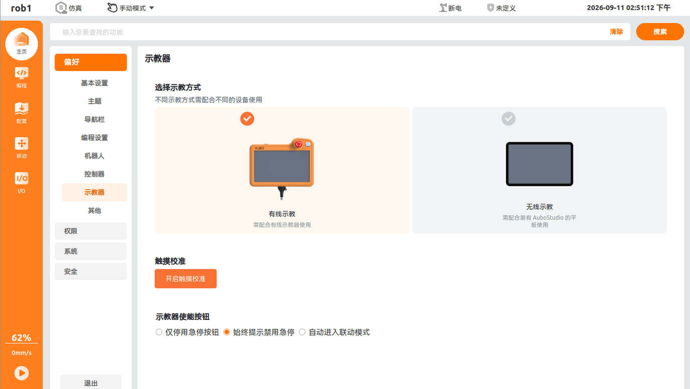
- Recommended action: Calibrate the touch screen again; if necessary, upgrade the host software and communication components; replace the relevant components if the cables or touch screen hardware are faulty.
- When to contact after-sales or technical support: If dead zones persist after calibration, obvious touch drift occurs, or the interface freezes frequently, contact the after-sales service team.
6.5 Motion Control, Joint, Collision, and CAN Communication Faults
Symptom: A joint angle is offset by plus or minus 360° after power-on
- Possible causes: Abnormality in the multiturn count of the absolute encoder, a pseudo-multiturn record that has not been cleared, or an abnormal joint position record.
- Diagnostic procedure:
- Identify the number of the affected joint and record the difference between the displayed angle after power-on and the actual posture.
- Check whether this problem occurs consistently every time the system is powered on.
- Verify whether the software version supports the multiturn recovery or pseudo-multiturn clearing procedure.
- Recommended action: Upgrade to a supported version following the multiturn recovery procedure provided by the after-sales service team, use the dedicated tool to clear the abnormal multiturn record, and then retest.
- When to contact after-sales or technical support: If the problem recurs after clearing, if multiple joints are affected simultaneously, or if the displayed angle does not match the actual posture, stop operation and contact the after-sales service team.
Symptom: A collision alarm persists and the robot arm cannot be released from the loaded state
- Possible causes: The robot arm is trapped by a fixture, clamp, or workpiece and remains under load, or the payload, center of mass, or collision level is set incorrectly, causing the alarm to be triggered again after it has been reset.
CAUTION
Do not repeatedly reset the alarm, force the robot to move, or disassemble components while the robot arm is under mechanical stress. If there is a risk of falling or spring-back, first support the robot arm and the workpiece reliably and clear the area of personnel.
- Diagnostic procedure:
- Stop the program and switch to manual mode, then identify the contact position and the direction of the force between the robot arm and the fixture, clamp, or workpiece.
- After the equipment has stopped and safety has been ensured, remove the obstacle or release the fixture constraint first. If the robot arm must be moved, trained personnel shall jog it for a short distance at minimum speed in the direction opposite to the applied force. Do not attempt to force the robot out of the trapped position using an automatic program.
- If the alarm is triggered again immediately after jogging, the collision sensitivity may be temporarily reduced under the guidance of the after-sales service team or an authorized technician. Restore the original collision level immediately once the robot has been released from the loaded position. Collision detection must not remain disabled over the long term.
- Check the mass and center of mass settings of the tool and workpiece, and check whether the base, clamps, and end-of-arm tooling are loose. Also check the clearances of the waypoints and fixtures, and reduce the speed and acceleration of the pick-and-place motions.
- After the corrections have been made, first perform a manual low-speed test run. If the alarm is still triggered repeatedly although there is no actual interference, save the alarm information, export the log and CSV data, and ask technical support to review the collision thresholds, joint parameters, and system real-time performance.
- Recommended action: Release the external force safely first, then correct the interference, payload, or motion parameters. Automatic operation may be resumed only after confirming that collision detection has been restored and that the low-speed test run runs correctly.
- When to contact after-sales or technical support: If the robot arm cannot be powered on or jogged, if the safe direction of escape cannot be determined, if the mechanical structure is deformed or damaged, if a joint makes abnormal noise or heats up abnormally, or if the alarm is still triggered repeatedly during a low-speed no-load run, stop the operation and contact the after-sales service team.
Symptom: False collision alarms during operation with a payload
- Possible causes: Inaccurate payload mass or center of mass settings, an excessively high collision level, excessive speed/acceleration, a loose base or fixture, or sudden acceleration and deceleration in the motion path.
- Diagnostic procedure:
- Check the actual mass, center of mass, and inertia settings of the end-of-arm tooling and workpiece.
- Check whether the robot base, fixtures, clamps, and end effector are securely fastened.
- Record the original collision sensitivity setting, then reduce the speed, acceleration, and collision sensitivity and retest.
- Check whether the alarm always occurs on the same path, in the same posture, or near the same joint.
- Recommended action: Recalibrate the payload parameters, optimize the path transitions, and reduce the speed of high-inertia motions. Once it has been confirmed that no actual collision occurs, restore the original collision sensitivity, re-verify the collision detection function, and only then resume production.
- When to contact after-sales or technical support: If a collision is still reported during a low-speed no-load run, if the same joint alarms repeatedly, or if abnormal noise or vibration is present, contact the after-sales service team.
Symptom: Excessive joint tracking error, target joint speed limit exceeded, or joint overspeed
- Possible causes: The target speed exceeds the actual capability of the joint; abrupt changes in joint angular velocity caused by short linear moves; a path passing close to a singularity; a mismatch between older hardware and the speed strategy of a newer host software version; or an abnormal joint/interface board firmware version.
- Diagnostic procedure:
- Record the program section, motion type, speed, acceleration, and posture at which the alarm occurs.
- Change short linear moves to joint moves, or add transition points between closely spaced waypoints.
- Reduce the speed and acceleration, and avoid singular postures or postures close to the joint limits.
- Check whether the host software, joint firmware, and interface board firmware versions match.
- Recommended action: Optimize the path first by reducing the speed, adding transition points, and using joint moves. For equipment that occasionally reports tracking errors after prolonged uninterrupted operation, upgrade the relevant firmware as recommended by the after-sales service team.
- When to contact after-sales or technical support: If tracking errors still occur during a no-load run at low speed, if a joint makes abnormal noise, or if the problem persists after the upgrade, contact the after-sales service team.
Symptom: The canbus: 0XFF or canbus: 0X08 alarm appears
- Possible causes: Open circuit or poor contact at the pins of the robot arm cable, abnormal 48 V supply, abnormal CAN line impedance, or a fault in a joint module or in the bus link.
- Diagnostic procedure:
- Record the CAN alarm code, the phase in which it occurs, and the faulty joint information.
- After de-energizing the equipment, inspect the robot arm cable connectors and the cable appearance.
- Measure the 48 V output while the robot arm is powered on, in compliance with the electrical safety requirements.
- Once the live voltage measurement has been completed, switch off the equipment again and disconnect the mains supply, taking measures to prevent unintended energization. After confirming that no hazardous voltage is present, measure the resistance of the CAN lines to determine whether the bus link is faulty.
- If the alarm consistently points to a specific joint or cannot be cleared after power-on, prepare the hardware diagnostic data.
- Recommended action: Restore the cables and the power supply chain first if they are faulty. If a joint module or bus hardware component is faulty, replace or repair it according to the after-sales procedure.
- When to contact after-sales or technical support: If a CAN alarm prevents power-on, if the alarm recurs, or if a joint module needs to be replaced, contact the after-sales service team.
6.6 Safety Protection and Stop Faults
Symptom: The system indicates that it has entered safety stop mode during operation
- Possible causes: A safety gate, light curtain, emergency stop, safety I/O, external reset circuit, or external safety wiring at the controller has been triggered; loose wiring on a safety device; an external PLC triggering a safety signal unintentionally.
- Diagnostic procedure:
- Check the status of the emergency stop button, safety gate, light curtain, and external safety devices.
- Check whether the external safety wiring at the controller is loose, disconnected, or incorrectly connected.
- Check the safety I/O status to determine whether the trigger originates from the robot itself, the controller, or external equipment.
- After eliminating the trigger source, reset the system according to the on-site safety procedure.
- Recommended action: Resume operation only after the wiring and safety device status have been correctly restored. If an external signal has been temporarily disconnected for diagnosis, the original safety circuit must be restored before retesting.
- When to contact after-sales or technical support: If the cause of the safety stop cannot be identified, if the safety signal status does not match the actual state, or if the safety function cannot be reset, stop operation and contact the after-sales service team.
6.7 Communication, Network, and Fieldbus Faults
Symptom: The controller cannot connect to the computer or host software over the network
- Possible causes: The IP addresses are not on the same network segment; incorrect subnet mask or gateway; a faulty network cable or switch; blocking by a firewall; IP conflict; incorrect static IP configuration on the controller.
- Diagnostic procedure:
- Verify that the computer network card and the controller are on the same physical network, and check the network cables, switch, and port indicators.
- Check the controller IP address, subnet mask, and default gateway.
- Check the IP address of the computer and verify that it is on the same network segment as the controller.
- Use
pingto test network connectivity. If the test fails, check the firewall, IP conflicts, and network isolation policies. - If a fixed controller address is required, configure a static IP address manually.
For example, to set the controller static IP address to 192.168.192.88, use the following parameters:
- IP address:
192.168.192.88 - Subnet mask:
255.255.255.0 - Default gateway:
192.168.192.1
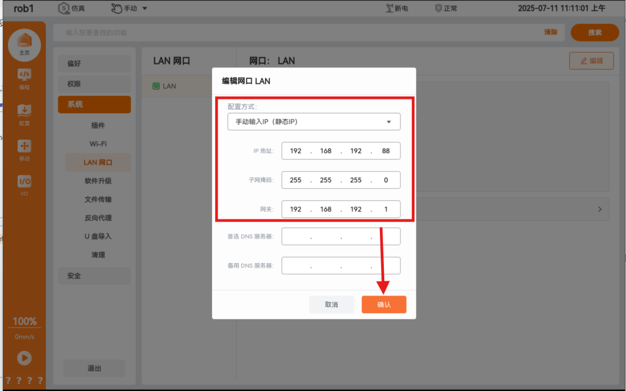
On Linux systems, the ifconfig command can be used to check the local IP address.
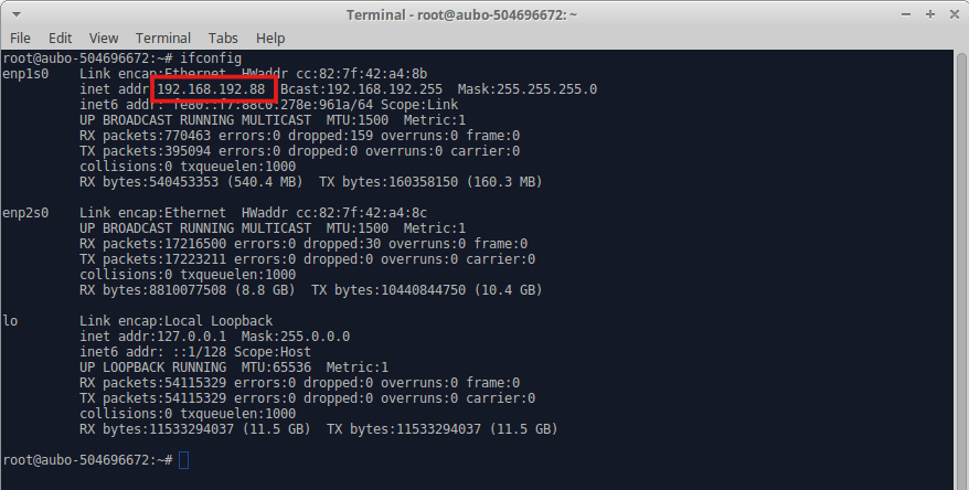
On Windows systems, the ipconfig command can be used to check the local IP address.
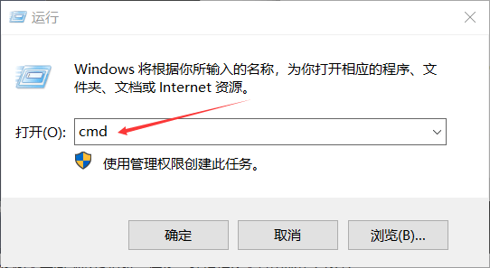
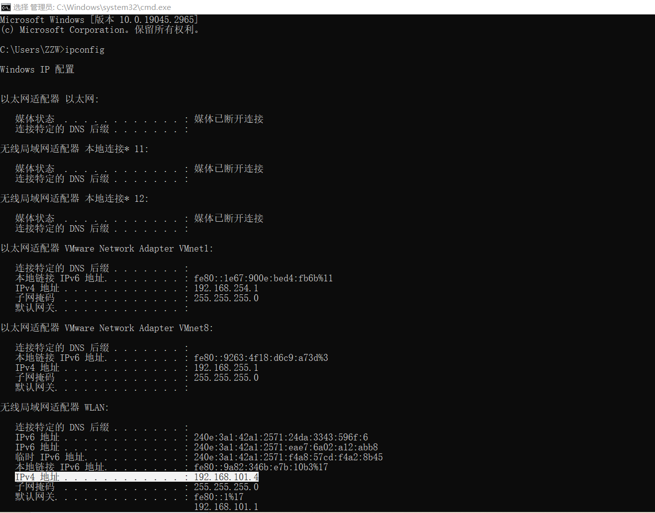
- Recommended action: Verify that the computer and the controller are on the same network segment and reconnect. If connection still fails, continue troubleshooting the firewall, switch, ports, and host software service status.
- When to contact after-sales or technical support: If the network is reachable but the controller service does not respond, if the web page cannot be opened, if SSH login fails, or if the communication service is interrupted repeatedly, export the logs and contact the after-sales service team.
Symptom: Modbus TCP / RTU communication fails, or written values do not take effect
- Possible causes: The network is unreachable; inconsistent serial port parameters; incorrect register address; the trigger address has not been written; the slave address table version does not match; firewall or IP conflict.
- Diagnostic procedure:
- For Modbus TCP, first verify that the device network is reachable, and check the firewall, IP address, and port.
- For Modbus RTU, check the serial port number, baud rate, parity, data bits, stop bits, and slave address.
- Check the slave address table and confirm the read/write addresses, data types, and byte order.
- For speed-write problems, verify whether a trigger register must also be written. For example, after a speed value is written, an activation command may need to be sent to the trigger address.
- Use a serial port debugging tool or a PLC monitoring table to confirm the data actually sent by the external device.
- Recommended action: Use the slave address table that matches the current system version, and retest reading and writing a single register once the communication parameters are consistent. If communication via the end-of-arm 485 interface fails, cross-test the 485 interface of the controller and the end-of-arm I/O status.
- When to contact after-sales or technical support: If the data remains abnormal although the address table matches and the link is normal, if the end-of-arm I/O is diagnosed as a hardware fault, or if the communication service crashes, contact the after-sales service team.
Symptom: EtherNet/IP communication fault, data errors, or the master station disconnects after an upgrade
- Possible causes: The PLC, controller, and computer are not on the same network; the EDS file has not been imported or its version does not match; incorrect I/O mapping; incomplete reading or writing of multi-byte data; the PLC configuration has not been updated after a software upgrade; plug-in resource conflict.
- Diagnostic procedure:
- Check the IP addresses and network topology of the PLC, controller, and commissioning computer.
- Check the EDS file, connection parameters, and I/O data length on the PLC.
- On the robot side, verify that the EIP / SEIP service is enabled, and observe whether the I/O monitoring data changes.
- If the master station shows a disconnection after an upgrade, check whether the EDS file and address table on the PLC and the compatibility settings on the robot have been updated accordingly.
- If the data read back is incorrect, verify whether multi-byte variables of 2 bytes, 4 bytes, and so on are being read and written in full.
- Recommended action: Import the EDS file that matches the current robot software version, and re-check the address table and data length. When switching from hardware EIP to software EIP, or in the case of a plug-in conflict, disable the conflicting plug-in according to the instructions in the relevant plug-in documentation.
- When to contact after-sales or technical support: If the communication service crashes frequently, if the PLC cannot establish a connection, or if the plug-in conflict cannot be located, contact the after-sales service team.
Symptom: Profinet / PN communication drops intermittently, or switching projects is not possible
- Possible causes: Incorrect device name, GSD file, I/O length, or address configuration on the PLC side; abnormal cyclic data on the PLC side; an incorrect IP address configured on the robot; a host software version that does not support project switching.
- Diagnostic procedure:
- Confirm that Profinet device addresses are assigned and managed by the PLC side, and do not configure a mismatched IP address on the robot side.
- Check the device name, GSD file, I/O length, update time, and diagnostic buffer on the PLC side.
- If projects must be switched over PN, verify that the host software version supports this function, and configure the program ID on the settings screen.
- Use the PLC monitoring table to verify that the program ID sent matches the configuration on the robot side.
- Recommended action: Correct the Profinet configuration and the abnormal data source on the PLC side, then upgrade to a host software version that supports PN project switching before configuring the program ID.
- When to contact after-sales or technical support: If PN communication drops continuously although the network is stable, if unexplained device faults appear in the PLC diagnostics, or if project switching does not respond, contact the after-sales service team.
6.8 Vision, Path, Force Control, and End-of-Arm Tooling Faults
Symptom: The robot and the vision system cannot send or receive TCP/IP or Modbus data correctly
- Possible causes: Mismatched IP address or port between the robot and the vision device; mismatched data frame format; incorrect register mapping; incorrect trigger timing; blocking by a firewall.
- Diagnostic procedure:
- Verify that the robot, the vision device, and the commissioning computer can communicate over the network.
- Check that the IP address, port, master/slave relationship, data format, byte order, and trigger timing are consistent on both sides.
- First verify the transmission and reception of a single data item using a simple script, then connect the complete vision positioning process.
- For coordinate transmission over Modbus, confirm the floating-point splitting method, the register start address, and the address table version.
- Recommended action: Standardize the communication protocol and data frame format, and use a demo script to verify transmission/reception, parsing, and motion triggering step by step.
- When to contact after-sales or technical support: If the robot-side communication service is abnormal although the network and protocol parameters are correct, if vision data cannot be parsed, or if the positioning error is unacceptable, contact the after-sales service team or the application support team.
Symptom: Position deviation in waypoints approached by vision positioning
- Possible causes: An outdated robot software or firmware version; inaccurate calibration data; incorrect tool or workpiece coordinate settings; inconsistent vision compensation data format.
- Diagnostic procedure:
- Check the vision calibration, tool coordinates, workpiece coordinates, and camera mounting condition.
- Check the coordinate units, coordinate system, and posture format sent by the vision system.
- Download and install the software and firmware package for the corresponding model, then retest.
- Recommended action: Review the coordinate systems and calibration first; verify the positioning accuracy again after upgrading the software/firmware.
- When to contact after-sales or technical support: If a consistent deviation remains after the upgrade and recalibration, submit the calibration data, program, and logs to the application support team.
Symptom: Path scripts, automatic return to Home, or workspace signals do not behave as expected
- Possible causes: The script cycle does not match the motion time; the path data has not been smoothed; interference on the return path; incorrect region boundaries or coordinate system settings.
- Diagnostic procedure:
- For servo motions such as
servoJ/servoC, verify that the call cycle matches the motion timet. - For third-party path files, filter and smooth the data first, then run it at low speed for verification.
- For automatic return to Home, verify that the joint sequence, speed, and intermediate points used for the return motion do not interfere with fixtures.
- For workspace signals, verify the judgement coordinate system, the region boundaries, and the corresponding output IO.
- For servo motions such as
- Recommended action: Verify the script logic first with low-speed, no-load, small-range motions, then gradually restore the actual speed and payload.
- When to contact after-sales or technical support: If a script causes abnormal motion, frequent overspeed alarms, or position inconsistency, pause the program and contact the application support team.
Symptom: Force control parameters, force sensor, or gripper plug-in faults
- Possible causes: A mismatched force sensor model or wiring; incorrect force control parameter configuration; an incorrect write address from external equipment; abnormal end-of-arm 485 or end-of-arm I/O; gripper plug-in configuration file not loaded.
- Diagnostic procedure:
- Confirm the sensor model, mounting orientation, wiring, and communication parameters according to the force sensor application documentation.
- Check the force control parameters, including mass, damping, stiffness, target force, and coordinate system.
- If external equipment changes the force control parameters in real time, verify that the variables or slave addresses are configured correctly.
- If the gripper cannot be connected, reload the plug-in configuration file and check the end-of-arm 485, the controller 485, and the plug-in serial port configuration.
- Recommended action: Configure all items one by one according to the official force control and force sensor documentation. If the end-of-arm 485 interface is faulty, reconnect it to the controller 485 interface as a cross-test.
- When to contact after-sales or technical support: If the force sensor produces no data, if gripper communication fails consistently, or if the end-of-arm I/O is diagnosed as a hardware fault, contact the after-sales service team.
Symptom: Incorrect position after a relative offset in a custom workpiece coordinate system
- Possible causes: When applying a relative offset directly to the origin pose, the pose was not first transformed into the target workpiece coordinate system, resulting in an inconsistent offset reference.
- Diagnostic procedure:
- Identify the workpiece coordinate system, waypoint, and offset direction currently in use.
- Before applying the offset, generate a variable pose based on the custom coordinate system, for example by using
poseTransto transform the waypoint to the target reference frame. - Then apply the relative offset to the transformed variable pose.
- Recommended action: Standardize the coordinate system reference used in the script. Use English variable names to avoid script transcoding problems.
- When to contact after-sales or technical support: If the position is still incorrect after the coordinate transformation logic has been verified, submit the project file and coordinate system configuration to the application support team.
6.9 Software Configuration, Upgrade, Permission, and Plug-in Faults
Symptom: The browser-based AuboStudio cannot be accessed, or the page does not respond after an upgrade
- Possible causes: The computer and the controller are not on the same LAN; the controller service is not started; abnormal browser cache; blocking by a firewall or port.
- Diagnostic procedure:
- Verify that the computer and the controller can communicate over the network, for example by running a
pingtest first. - Access
controller IP:9090in the browser. - If the page cannot be opened, check the status of key services such as
nodeandnginxin the controller. - If buttons do not respond or the page is slow after an upgrade, clear the browser cache, or access the page again in incognito mode.
- Verify that the computer and the controller can communicate over the network, for example by running a
- Recommended action: Restore the network and services, then try to access the page again. Clear the cache first after an upgrade to prevent old front-end resources from affecting the page.
- When to contact after-sales or technical support: If the page still cannot be accessed after the services have been restored, if the page crashes frequently, or if the controller services cannot be started, contact the after-sales service team.
Symptom: Plug-in conflict, a greyed-out update button, or a program script loading error
- Possible causes: Plug-in resource conflict; insufficient permissions for the current account; abnormal project script status; a defect in the host software version.
- Diagnostic procedure:
- If the message "Set IO failed" appears when the ICM and SEIP plug-ins are used at the same time, check whether a plug-in resource conflict exists.
- If the Update button is greyed out and cannot be clicked, verify whether the current login account has the permissions required for upgrading or configuration.
- If a "program script loading error" appears although the project contains no scripts, record the project file and the software version.
- If an error occurs when assigning a value to a variable pose in a script, check whether the variable name contains Chinese characters or special characters.
- Recommended action: Disable or delete unnecessary conflicting plug-ins; switch to an account with the required permissions; upgrade the host software version; use English variable names in scripts.
- When to contact after-sales or technical support: If errors persist after the plug-in has been removed, if account permissions are abnormal, or if the project cannot be loaded, contact the after-sales service team.
Symptom: An OEM customized software package needs to be installed
- Possible causes: The customized function has not been imported; the OEM file has not been enabled; the configuration does not take effect after restarting.
- Diagnostic procedure:
- Import the OEM package into the controller and verify that the files are complete and of a matching version.
- Enter expert mode and add and select the OEM file on the Production/OEM page.
- Select the enable option, then shut down and restart the system.
- Recommended action: Complete the import, enabling, and restart according to the OEM package instructions. Back up the project before upgrading or replacing an OEM package.
- When to contact after-sales or technical support: If the OEM package cannot be imported, if the system behaves abnormally after enabling, or if enabling does not take effect after restarting, contact the after-sales service team.
6.10 Diagnostic Information and Logs
If a fault cannot be resolved using basic on-site checks, prepare the diagnostic material before contacting the after-sales service team, to avoid repeated communication and the omission of key evidence.
| Information type | Description |
|---|---|
| Equipment information | Robot model, serial number, controller model, teach pendant model, system type (PE / ARCS). |
| Software information | Host software version, joint/interface board firmware version, plug-in version, project file version. |
| Fault information | Alarm code, alarm text, time of occurrence, frequency, whether the fault is reproducible, and the most recent operation before the fault. |
| On-site status | Power supply voltage, earthing, external safety devices, and the connection status of peripherals such as PLC / vision systems / grippers. |
| Evidence | Alarm screenshots, site photos, operation videos, program fragments, logs, and event reports. |
| Actions already taken | Items checked, parameters adjusted, components replaced, and retest results after each action. |
Common methods for exporting logs and files are as follows:
- Export from the log center: Generate an event report in the log or event center of the control software, download it, and submit it together with the fault information.
- Export via SSH / SFTP: Once the computer and the controller can communicate over the network, use a tool such as MobaXTerm to copy logs, projects, or configuration files via SSH / SFTP.
- Scenarios without a USB flash drive: If USB flash drives are not permitted in a secure workshop, give priority to exporting via SSH, SFTP, or a LAN transfer method approved on site.
- Export precautions: Do not arbitrarily delete, move, or overwrite controller system files. After exporting, store the log and project files securely to prevent the disclosure of process information.
6.11 Fault Reporting and After-Sales Support
Stop the equipment immediately and contact the AUBO after-sales service team in any of the following situations:
- Abnormal safety functions, an unidentifiable cause for the safety stop, or an emergency stop or safety I/O that cannot be reset.
- Abnormal robot motion, joint droop, brake malfunction, obvious abnormal noise, impact deformation, or structural damage.
- Unusual odor, smoke, signs of burning, repeated tripping, or abnormal heating of live parts in the controller or power supply components.
- Software that cannot start, a failed upgrade, a project that cannot be loaded, or communication services that crash frequently.
- High-risk operations required on site, such as disassembly, wiring modification, joint module replacement, brake release, or return-to-factory packing.
The following material is recommended when contacting the after-sales service team:
- Equipment model, serial number, controller model, system type, and software/firmware version.
- Alarm screenshots, alarm codes, time of occurrence, reproduction steps, and on-site video.
- Whether any relocation, upgrade, repair, component replacement, wiring modification, collision, or fixture modification has recently taken place.
- The troubleshooting steps already performed and the result after each step.
- Logs, event reports, project files, or the necessary configuration files.
Before returning the robot to the factory or arranging on-site repair, move the robot arm to a safe posture and secure it mechanically. If a joint fault prevents the robot from reaching the packing posture, de-energize the equipment and release the brake of the relevant joint under the guidance of the after-sales service team, and secure the robot arm with reliable supports and cushioning material to prevent secondary damage during transportation.
7 Appendix
7.1 Revision History
| Version | Date | Description of revision |
|---|---|---|
| v1.0.0 | 2026-09-07 | First release. |