AUBO Welding Application Manual
1 Foreword
A welding process package is a process plugin developed based on ARCS system, specifically designed for AUBO robot welding application scenarios. It adopts a classic sequential logic programming architecture with a simple and intuitive operation process, allowing even beginners to quickly get started.
The plugin system is equipped with an advanced algorithm framework, combined with a newly designed welding interaction interface, which enhances operational convenience while providing full-cycle technical support from installation and debugging to subsequent maintenance. The welding process package is equipped with general analog communication protocols such as I/O and Modbus TCP, compatible with various mainstream welding machine models on the market, helping the operator easily achieve unified control of welding machines of different brands and models.
This manual systematically explains the standard operation and safety guidelines of the welding process package. To avoid operation risks, all operators must read through the operation steps one by one before use to ensure complete mastery of the relevant key points. Special attention should be paid to the fact that the example images in the manual are for reference only; actual equipment may differ in interface and function display depending on the model and version.
2 Safety information
Since robot welding involves many potential hazards, users must carefully read, understand, and abide by this manual and other instructions regarding the AUBO robot user manual before use.
Integrators must ensure that the complete robotic system in the installation area meets the requirements of relevant laws and regulations, strictly carry out safety line assessments, and take necessary measures to minimize risks. At the same time, users must abide by the safety regulations specified by the integrators.
2.1 Grounding Safety
2.1.1 Safety Warning
Important Safety Requirements: To ensure the safety of operators and the normal operation of equipment, AUBO strictly requires that the robotic arm must be connected to a qualified protective grounding wire (PE wire) before it can be powered on and used. It is forbidden to start the equipment without connecting the PE wire.
Compliance Standards: This requirement complies with the IEC 61140 electrical safety standards and equipment usage specifications, and is a basic prerequisite for ensuring the safety of personnel and equipment.
2.1.2 Security Risks
Induced electricity risk: When the robotic arm is not connected to the PE wire, the shell may carry an induced voltage of 15V ~ 105V. When operators come into contact with it, they may experience discomfort such as a tingling or stinging sensation in the hands, which could cause panic and incorrect operations, leading to secondary injuries such as collision with the robotic arm or accidental triggering of the emergency stop.
Risk of Equipment Damage: An ungrounded state may potentially damage electrostatically sensitive electronic components, causing malfunctions in the robot control box and even substantial damage to the power supply unit.
Compliance Risk: Failure to properly ground does not comply with electrical safety regulations, posing serious safety hazards and potentially leading to safety accidents and legal liabilities.
2.1.3 Security Measures
Forced grounding: A qualified PE wire must be connected to the robotic arm to ensure a good electrical connection between the shell and the earth.
Grounding Requirements:
- Wire Specifications: The cross-sectional area of the PE wire must be ≥ 2.5mm² (copper core cable), with no damage to the insulation layer and secure crimping.
- Grounding Resistance: After the grounding construction is completed, a grounding resistance tester must be used to measure between the robot arm's PE terminal and the earth. A grounding resistance of ≤ 4Ω is considered qualified (in accordance with the IEC 61140 standard).
- Record Retention: Grounding test records must be retained for filing as an important proof of safety compliance.
2.1.4 Safety Inspection
Daily Inspection: Operators should regularly check the connection status of the PE line to ensure there is no loosening, breakage, or corrosion.
Maintenance Requirements: After equipment maintenance, relocation, or reinstallation, the grounding resistance must be retested to ensure the grounding system remains effective.
Training Requirements: All operators must receive grounding safety training to understand the risks of improper grounding and the correct grounding methods.
AUBO reminds users:
When using the robot, please pay attention to the safe use of the equipment. The robot operators must be responsible for their own safety. AUBO is not responsible for safety issues arising from the use of the robot.
3 Version information
| Version information | Version number |
|---|---|
| Manual Version | AUBO Welding Application Manual - 1.1 |
| Wired Welding Process Package Version | welding-0.1.9-beta.2 and above |
| Wireless Welding Process Package Version | webwelding-0.2.1-beta.1 and above |
| ARCS Version | 0.31.1-rc.34 and above |
4 Hardware Modules
4.1 Product Introduction
Welding Workstation - W5 Component Diagram:
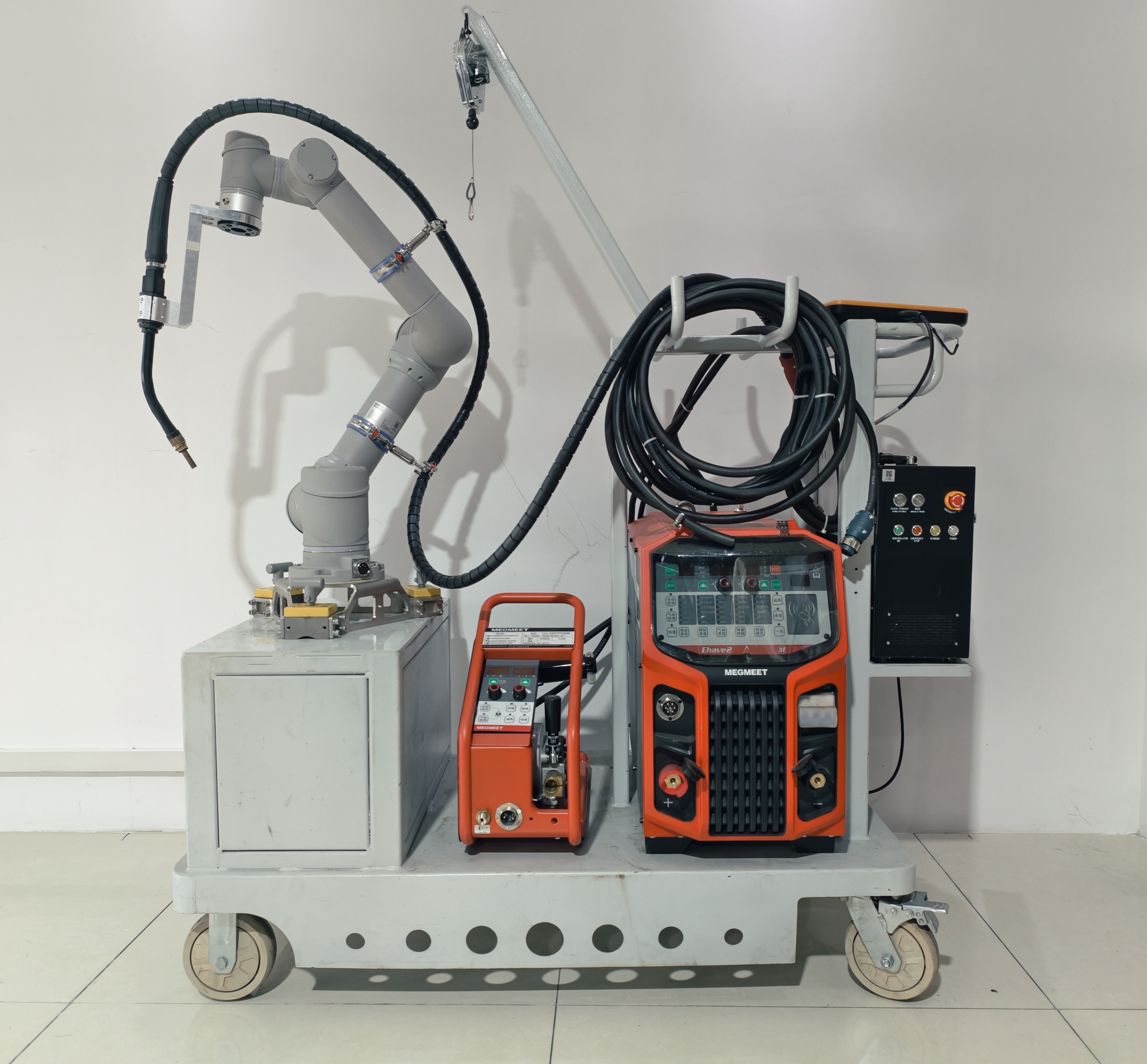
Product components:
Trolley
Welder Ehave2 500M
Wire feeder
Welding torch
Welding torch fixture
Magnetic base
Robot control cabinet
Robotic arm
Teach pendant | Tablet
6D mouse set
Gun cable hanger and bracket
Cables (control cabinet power cord, robotic arm power cord, one welder IO communication cable, welder positive cable, air pipe, welder negative cable)
4.2 Operational Specifications
4.2.1 Wiring Check
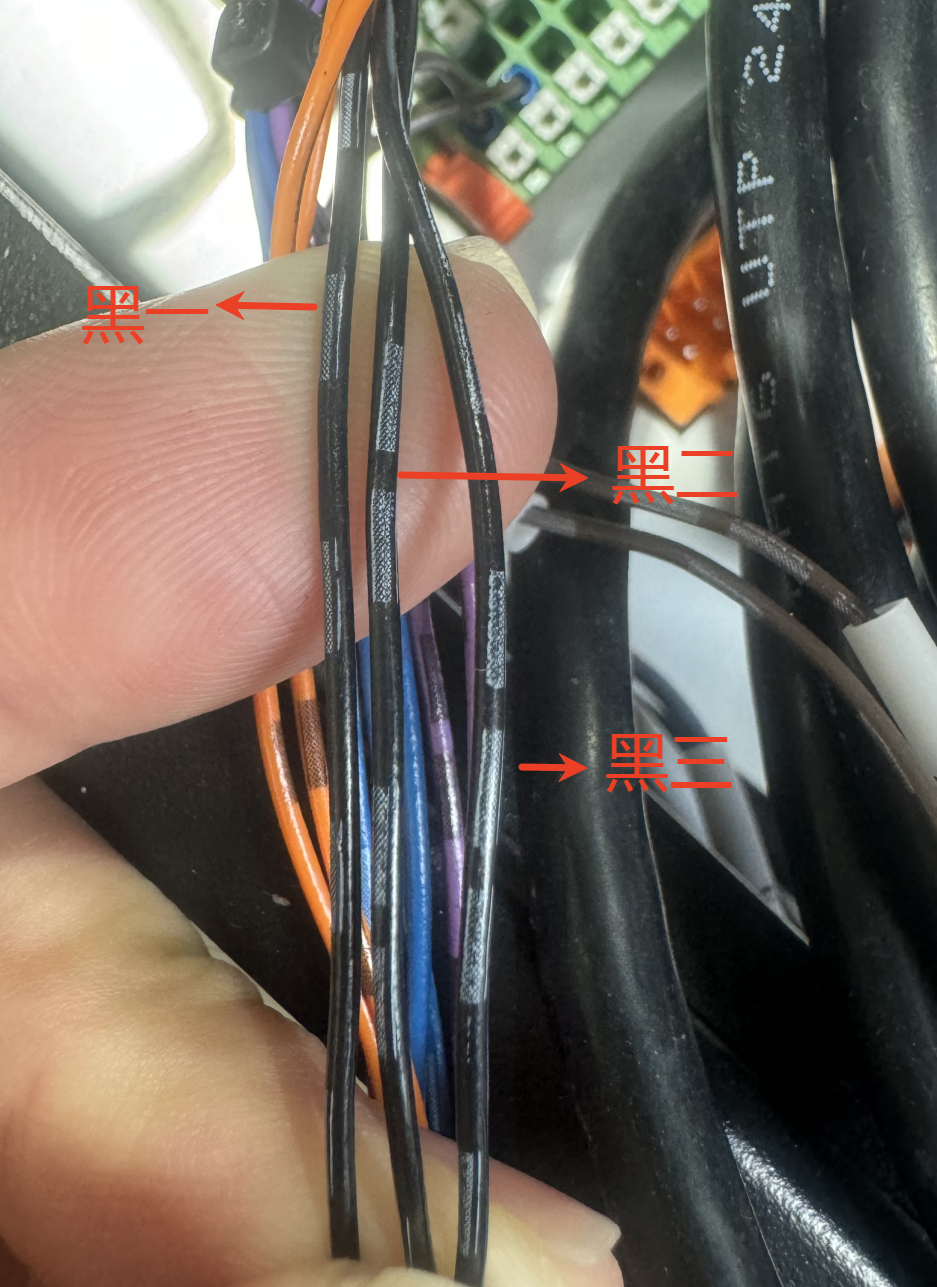
The commonly used welding machine at present is the Megmeet welding machine, with the wiring signals as follows:
| Function | Wire Sequence | IO Port |
|---|---|---|
| 24V Power Supply | Black 1 | 24V |
| Arc Start Signal | Black 2 | DO00 |
| Reverse Wire Feed Signal | Black 3 | DO01 |
| Arc Start Success Signal | Brown 1 | DI00 |
| IO Signal Common Ground | Brown 3 | 0V |
| Wire Feed Signal | Orange 1 | DO02 |
| Gas Detection Signal | Orange 3 | DO03 |
| Welding Current Signal | Purple 2 | AI0 |
| Current Setpoint Signal | Purple 3 | AO0 |
| Analog Signal Common Ground | Blue 1 | 0V/GND |
| Welding Voltage Signal | Blue 2 | AI1 |
| Voltage Setpoint Signal | Blue 3 | AO1 |
Wire sequence description: Black 1, Black 2, Black 3
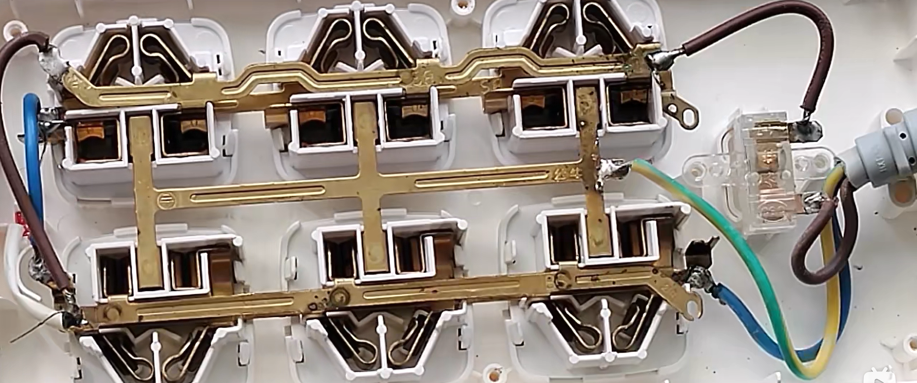
4.2.2 Inspection of Site Grounding Wire
Error Situation:
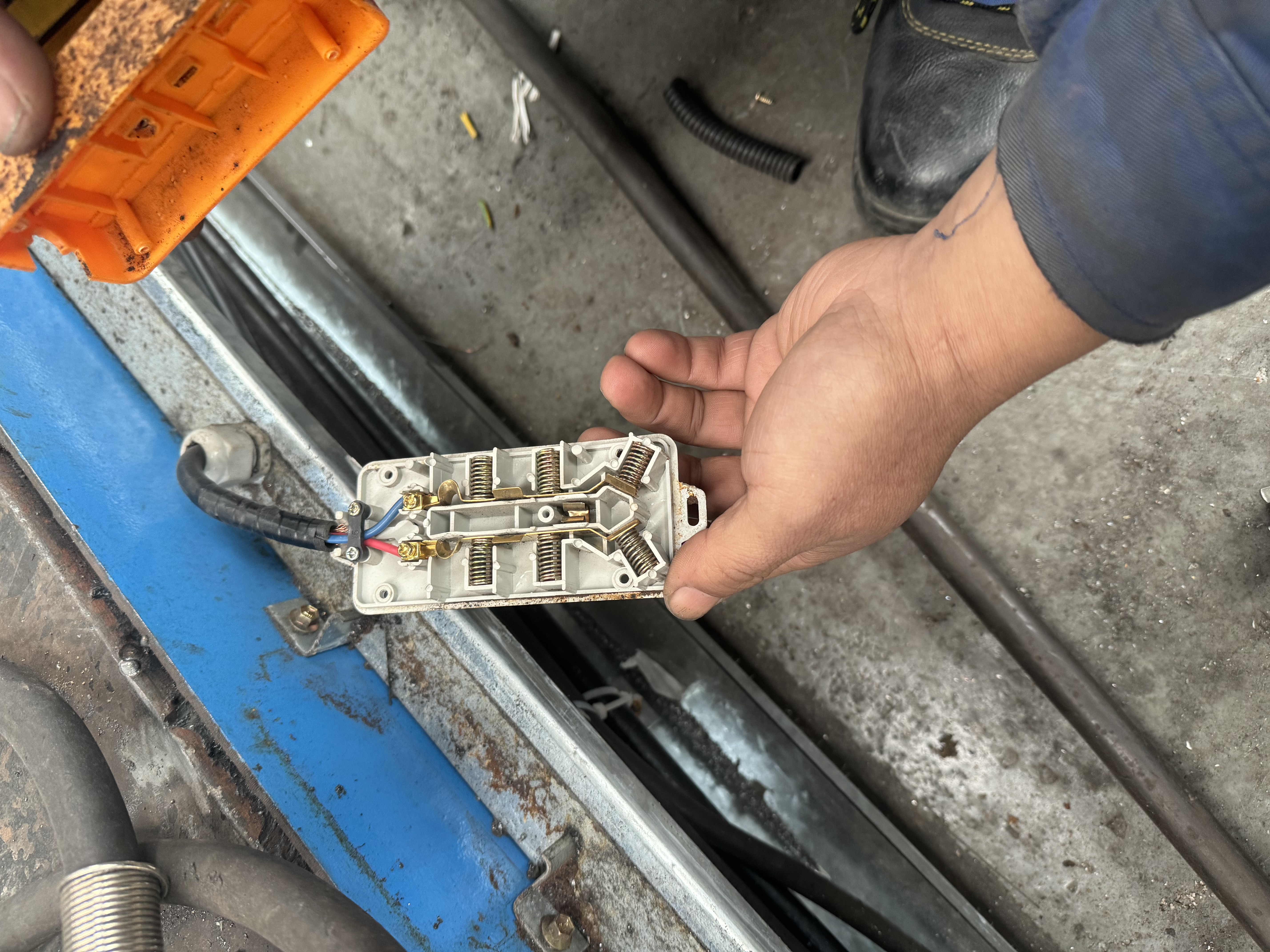
Correct situation:
5 Installation of welding process package
A welding process package is a process plugin developed based on the ARCS. Please ensure that you have installed the AuboStudio software before installing the process package.
The installation steps of the welding process package are as follows:
Download the welding process package from the official website to a USB flash drive, and insert the USB flash drive into the USB interface of the robot control box. Download link: Contact AUBO staff.
Open the teach pendant, click "Home > Setting > System > UDisk Import", select the welding process package, and click [Import].


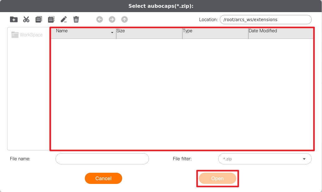
Click [AuboCaps] to enter the plugin interface, click [Add] in the lower left corner of the interface, select the welding process package file, and click [Open] to import the welding process package.
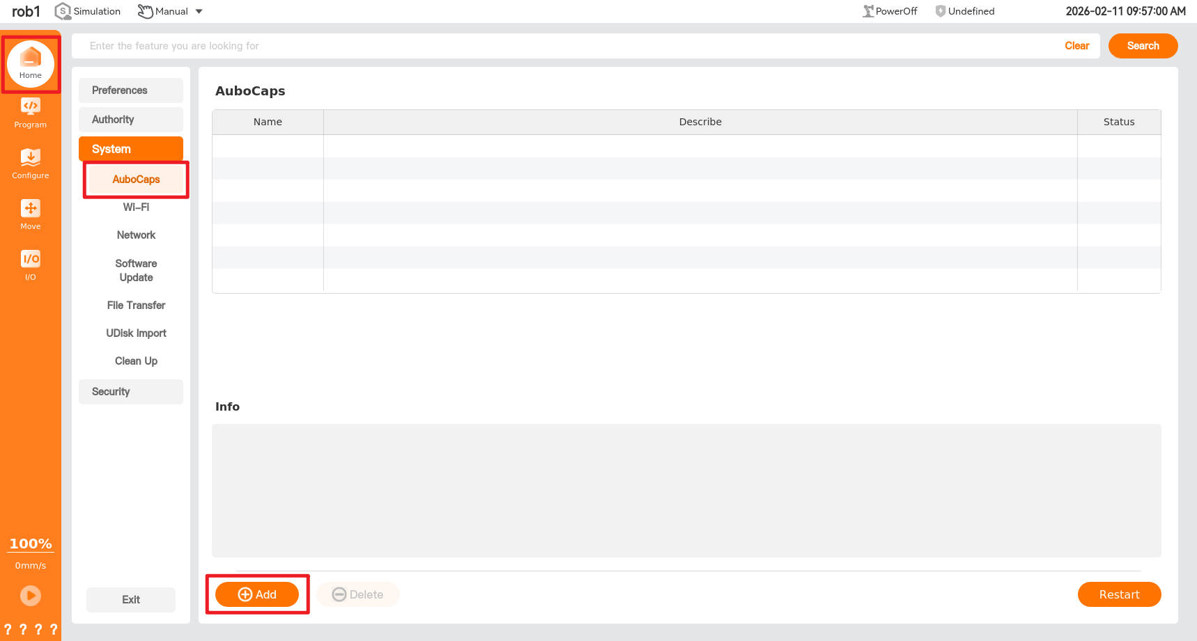
Set the status button of the process plugin "Welding" to green, and click [Restart] to restart the control box.
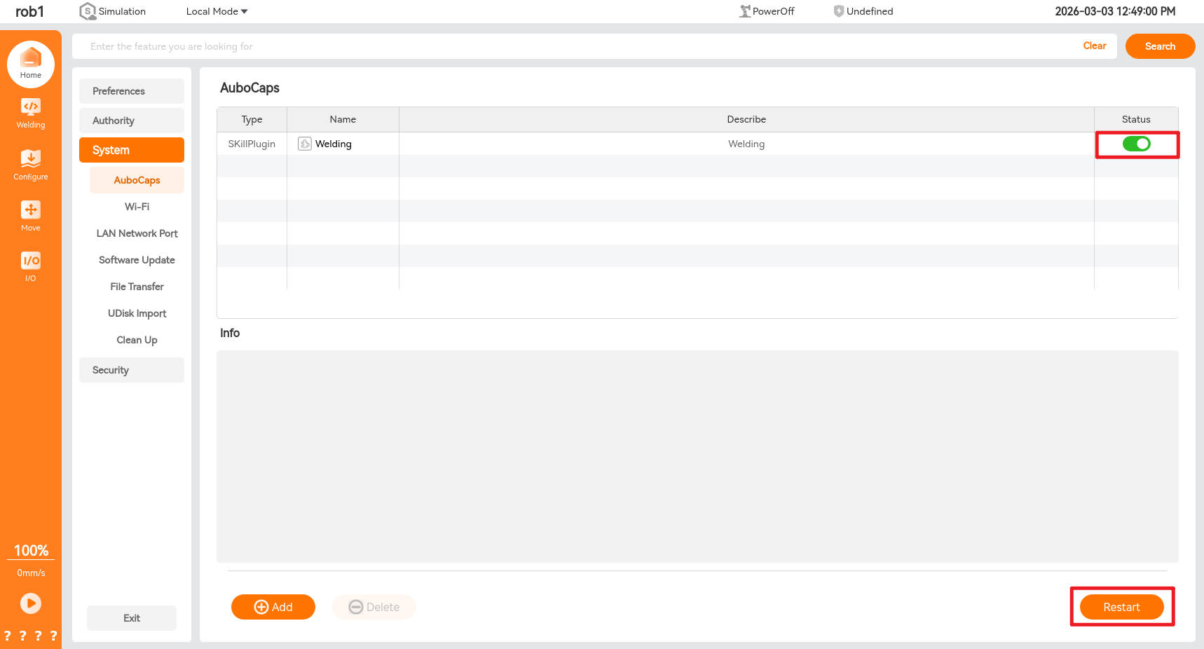
After the control box restarts successfully, you can view the newly added plugin functions in [Plug-in] and "Configure > Welding".

6 Basic configuration
When using the welding process package for the first time or after replacing the welding machine, you must first perform parameter configuration for the robot and welding machine, including configuring the robot’s tool center point (TCP), load, welding machine’s communication mode, etc. Users can manually configure these functions themselves or import an existing installation profile for configuration, as shown in the figure below.
Note:
After completing the configuration, you must save the configuration file before writing the program file to ensure that the set parameters take effect.
If the configuration file is modified and is already bound to a program file, you must save the configuration file first and then save the program file to avoid program execution errors.
6.1 Tool center point (TCP)
6.1.1 TCP position calibration
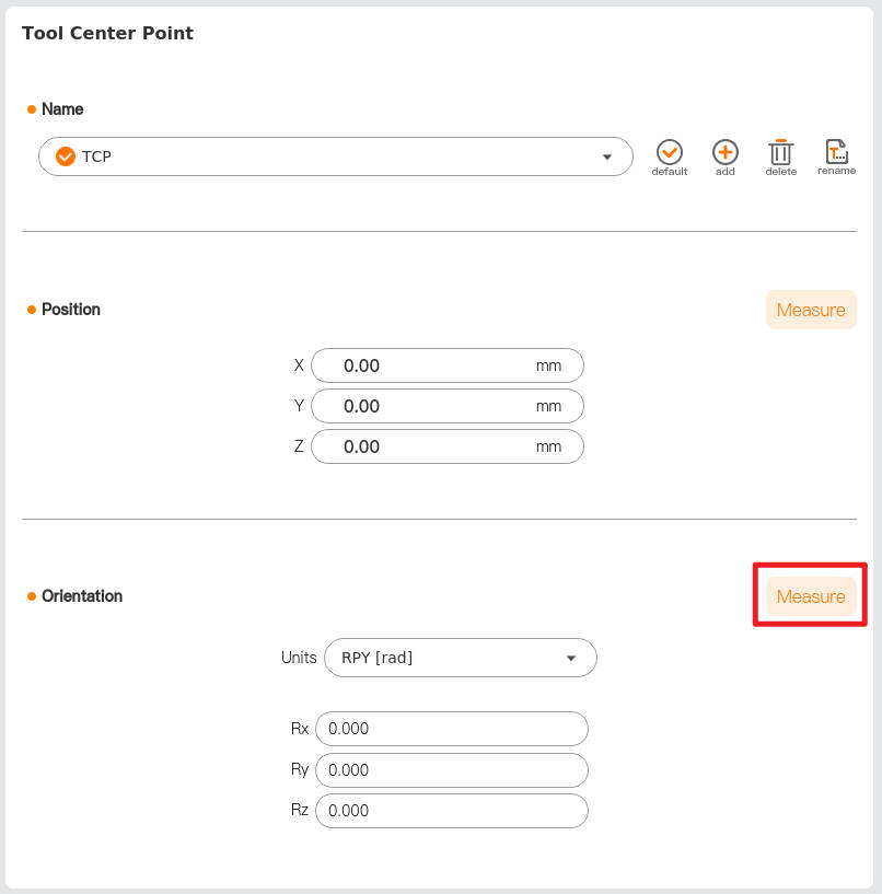
Open the teach pendant and click "Configure > Generally > TCP".

Click [Add] to create TCP_0, click [Rename] to rename the tool coordinate system, and click "Position > Measure" to enter the [Teach TCP Position] wizard.

The TCP position is determined by the four-point method, i.e., locating a fixed reference point (usually a sharp point) and teaching four different poses of the robot tool's end tip around this reference point. The system automatically calculates the TCP position based on the data from these four positions. The differences in the poses of these four positions should be as large as possible, and after setting the four points, you can add waypoints to improve calculation accuracy.

Click to set waypoint 1, and you will enter the following interface. Follow step 1 to change the robot arm attitude so that the tool tip contacts the tip of the calibration tool. After setting the waypoint, click to [OK]. Proceed to set the next waypoint. The remaining waypoints follow the same method.

6.1.2 TCP direction calibration
Click "Orientation > Measure" to enter the [Teach TCP Orientation] wizard.
Select a coordinate system, and click [Set point] to enter the teaching interface. After setting the waypoint, click to view the direction calculated by the system.

- Use the teaching interface or HandGuide to change the robot arm attitude so that the welding torch is vertically upward, which is the positive direction of the Z-axis.

Click [Default] and [Save] in sequence to apply and save the newly created TCP.

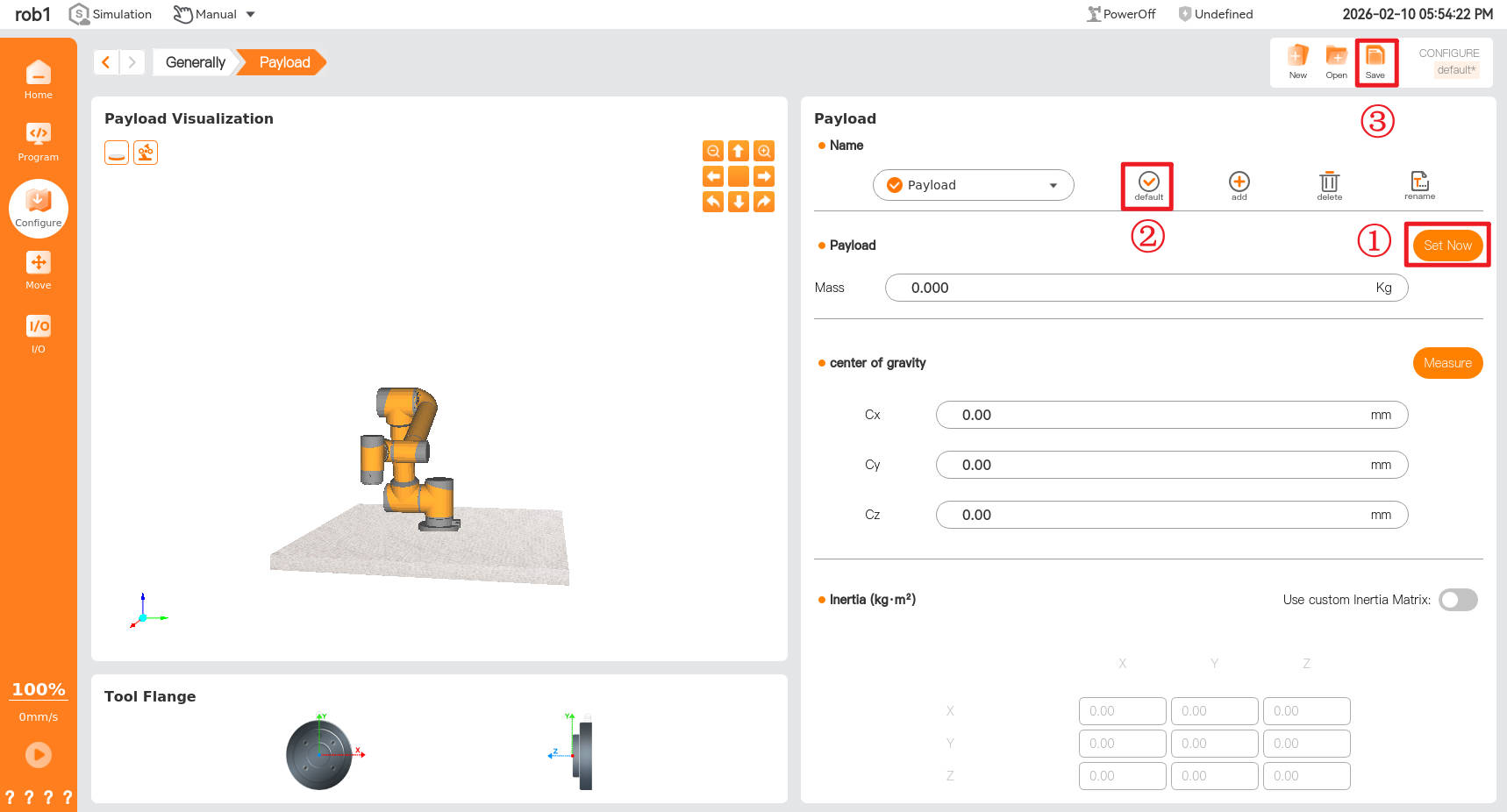
6.2 Payload
Open the teach pendant and click "Configure > Generally > Payload".

Click [Add] to create a new payload, and click [Rename] to rename the new payload.
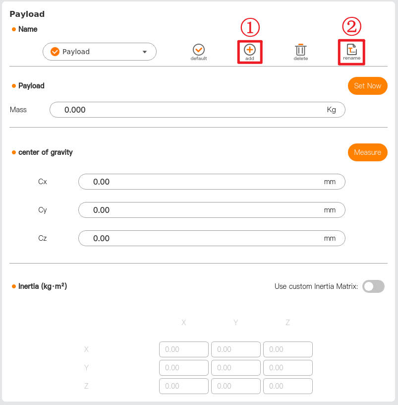
Click [Measure] to enter the payload identification wizard, and measure the payload parameters according to the wizard prompts.

Click [Set Now], [Default], and [Save] in sequence to apply and save the newly created payload.
7 Welding configuration
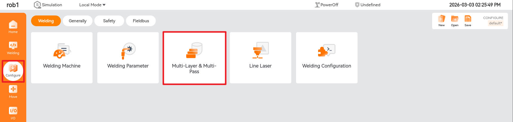
Click "Configure > Welding" to enter the welding configuration interface. The welding configuration currently includes five parts: "Welding Machine" configuration, "Welding Parameters" configuration, "Multi-layer and Multi-pass Welding" configuration, "Line Laser" configuration, and "Welding Configuration" configuration.
7.1 Welding machine
Click [Welding Machine] to enter the welding machine configuration interface, which contains three modules: "Welding Machine Configuration," "Communication Status," and "Welding Machine Operation."

7.1.1 Welding machine configuration
When using for the first time or replacing the welding machine, you can configure "Welding Type," "Welding Machine Type," "Communication Settings," and "Operation Mode" in the dropdown box according to actual needs, set "Communication Configuration" according to actual application requirements, and test parameters in "Simulation Curve."
- Welding type: Select the welding type of the welding machine, such as arc spot welding, laser welding, etc.
- Welding machine type: Select the corresponding welding machine brand and model and communication settings.
- Select the communication method between the welding machine and the robot, such as robot I/O, Modbus TCP, etc.

I/O communication address configuration:
Click [Communication Settings] to configure the robot I/O signal address corresponding to the welding machine as needed. As shown in the figure below, click [Save] after completing the configuration.

Click [Simulation Curve] to set the current and voltage analog signals given by the robot to the welding machine and set the current and voltage analog signals fed back from the welding machine to the robot, as shown in the figure below. Click [Save] after completing the settings to finish the configuration.


7.1.2 Communication status
The communication status of the welding machine includes connection status, welding machine ready, arc start success, wire feed, wire retract, gas supply, feedback current, and feedback voltage. In the communication status, a green icon indicates successful communication, while a red icon indicates communication failure.

7.1.3 Welding machine operation
The welding machine operation function can manually test actions such as "wire feed," "wire retract," "tackweld," and "gas feeding." Clicking "Manual Tack Weld" can test arc initiation, and you can view the welding effect of the actual welding current and voltage in the "Set Current" and "Set Voltage" display boxes.

7.2 Welding parameters
The welding parameters are parameters related to the robot's motion and welding process when the robot performs welding actions. They are mainly divided into global motion parameters, welding process parameters, and swing parameters.
- Global motion parameters: These are the motion parameters of the robot's preparatory actions before and after the welding action.
- Welding process parameters: These are the robot's running speed and the welding machine's operating current, voltage, and other process parameters set during the welding action.
- Swing parameters: These are the relevant parameters of the robot's swing process when the robot performs a welding swing (zigzag swing, crescent swing, etc.).
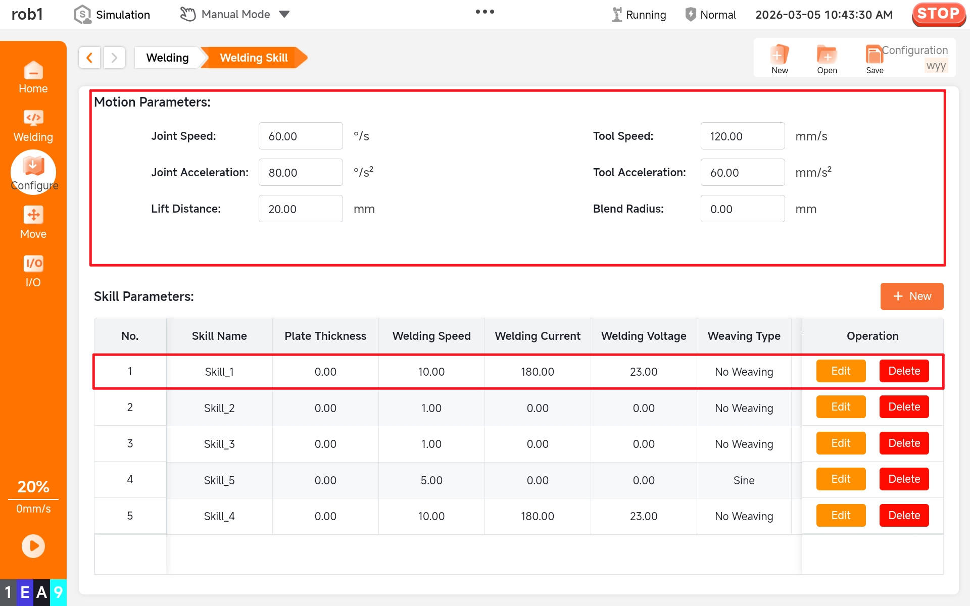
7.2.1 Global motion parameter
The global motion parameter settings are shown in the figure below, including joint speed, joint acceleration, tool speed, tool acceleration, lifting distance, and blend radius. The lifting distance is the preparation distance automatically generated in the opposite direction of the initial posture when TCP enters the weld start point or leaves the weld end point.


Joint/tool speed: Set the movement speed of the joint when the [Move] node is set to "MoveJ." Set the movement speed of the tool when the [Move] node is set to "MoveL."
Joint/tool acceleration: Set the movement acceleration of the joint when the [Move] node is set to "MoveJ." Set the movement acceleration of the tool when the [Move] node is set to "MoveL."
Use of blend radius: Set the default blend radius of the [Waypoint] node under the [Move] node when the [Move] node is set to "MoveL."
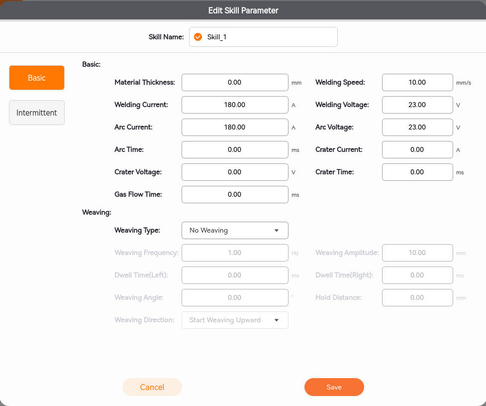
7.2.2 Welding process parameters
Click [New] to add process parameters. Click [Edit] to set process parameters. After setting process parameters, you can select or deselect [Default Parameters]. Once selected, click [Save] to complete the welding parameter settings.

The welding process parameters include plate thickness, welding speed, welding current, welding voltage, arc extinguishing voltage, arc extinguishing current, arc extinguishing time, and gas supply time, which can be configured according to actual process requirements.
- Plate thickness: The thickness of the welding plate, in millimeters (mm);
- Welding speed: The speed at which the welding torch moves along the welding direction during the welding process, expressed in millimeters per second (mm/s);
- Welding current: The current intensity during welding, measured in amperes (A);
- Welding voltage: The voltage used during welding, measured in volts (V).

- Arc ignition voltage: The voltage value of the electric arc at the start of welding, which is usually lower than the normal welding voltage;
- Arc ignition current: The current value of the electric arc at the start of welding, which is usually lower than the normal welding current;
- Arc initiation time: The time from the start of the arc ignition procedure (such as the current/voltage starting to decay) to the electric arc reaching the set voltage and current, in milliseconds (ms);
- Arc extinguishing voltage: The voltage value of the electric arc at the end of welding, which is usually lower than the normal welding voltage;
- Arc extinguishing current: The current value of the electric arc at the end of welding, which is usually lower than the normal welding current;
- Arc extinguishing time: The time from the start of the arc extinguishing procedure (such as the current/voltage starting to decay) to the electric arc reaching the set voltage and current, in milliseconds (ms);
- Gas supply time: The delivery time of welding shielding gas, which usually includes two stages: "pre-supply" and "delayed gas stop," measured in milliseconds (ms).

7.2.3 Swing parameters
- Swing parameters: Swing type, swing frequency, swing amplitude, dwell time, holding distance, angle, and direction.
- Swing type: Including non-swing, sine, spiral, crescent, and zigzag.
- Swing frequency: The swing frequency is the number of cycles per second, measured in Hz.
- Swing amplitude: The maximum value of the swing (as shown in the figure below).
- Dwell time: The time the robot arm stays when it swings to its peak value. The figure below shows the dwell time at points 1 and 2.
- Holding distance: The distance the robot arm moves in the forward direction after the robot arm swings to its peak value. This is the holding distance, as shown in the figure below, specifically the distance moved in the direction of the arrow at points 1 and 2.
- Weaving angle: The direction of the robot arm rotating counterclockwise around the X axis of the motion tool coordinate system is positive.
- Swinging direction: Upward swinging and downward swinging (the swinging direction in the figure below is upward).

The figure below shows the motion track of a robot arm with a sine swing frequency of 1 Hz, an upward swing direction, a dwell time of 0 ms, a holding distance of 0 mm, and a swing angle of 0°.

- Figure [1] shows the motion track of the robot arm with a zigzag swing frequency of 1 Hz, an upward swing direction, a dwell time of 0 ms, a holding distance of 0 mm, and a swing angle of 0°.
- Figure [2] shows the motion track of the robot arm with a zigzag swing frequency of 1 Hz, an upward swing direction, a dwell time of 0 ms, a holding distance of 0 mm, and a swing angle of 20°.
- Figure [3] shows the motion track of a robot arm with a zigzag swing frequency of 1 Hz, an upward swing direction, a dwell time of 0 ms, a holding distance of 0 mm, and a swing angle of 90°.
- Figure [4] shows the motion track of the robot arm with a zigzag swing frequency of 1 Hz, a downward swing direction, a dwell time of 0 ms, a holding distance of 0 mm, and a swing angle of 0°.
Click [Edit] to configure the process parameters as shown in the figure below. After setting, click [Save] to complete the configuration.
7.3 Multi-layer and multi-pass welding
7.3.1 Add and save processes
Click [Add] to create a new multi-layer and multi-pass welding project.

7.3.2 Basic configuration of multi-layer and multi-pass welding
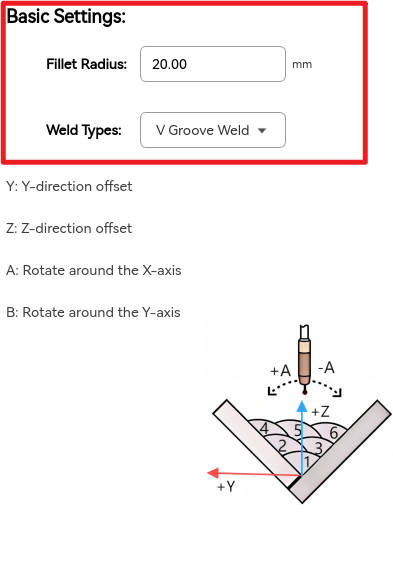
The basic multi-layer and multi-pass welding configuration includes "fillet radius" configuration and "weld type" selection. The transition radius generally does not need to be modified, and the weld types include V-type welds and fillet welds.
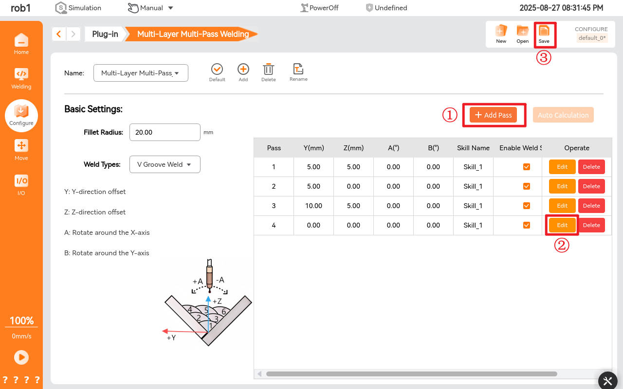
7.3.3 Add pass for multi-layer and multi-pass welding
Click [Add Pass] to offset the track of the newly added weld relative to the base weld. Click [Edit] to configure the offset. Select [Enable Weld] to activate the offset weld settings. After completing the selections, click [Save] to finalize the multi-layer and multi-pass welding process configuration.
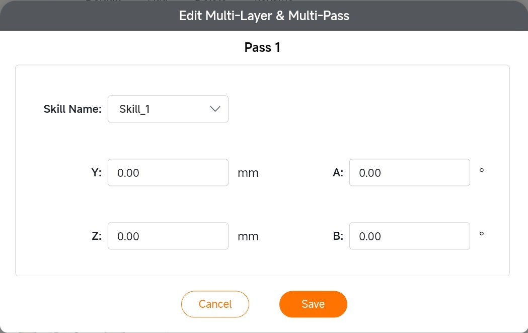
7.3.4 Offset of multi-layer and multi-pass welding and end-of-arm rotation angle
V-type weld:
Y represents the horizontal leftward offset, Z represents the vertical upward offset, and the direction from the weld start point to the weld end point is the positive direction of the X axis. A is the angle of rotation about the X axis, with rotation about the X axis to the Y axis being positive, and B is the angle of rotation about the Y axis. Click "Edit" to enter the settings for offset of multi-layer and multi-pass welding and end-of-arm rotation angle. Select the process name and offset of the specific pass you want to edit. After setting, click "Save."
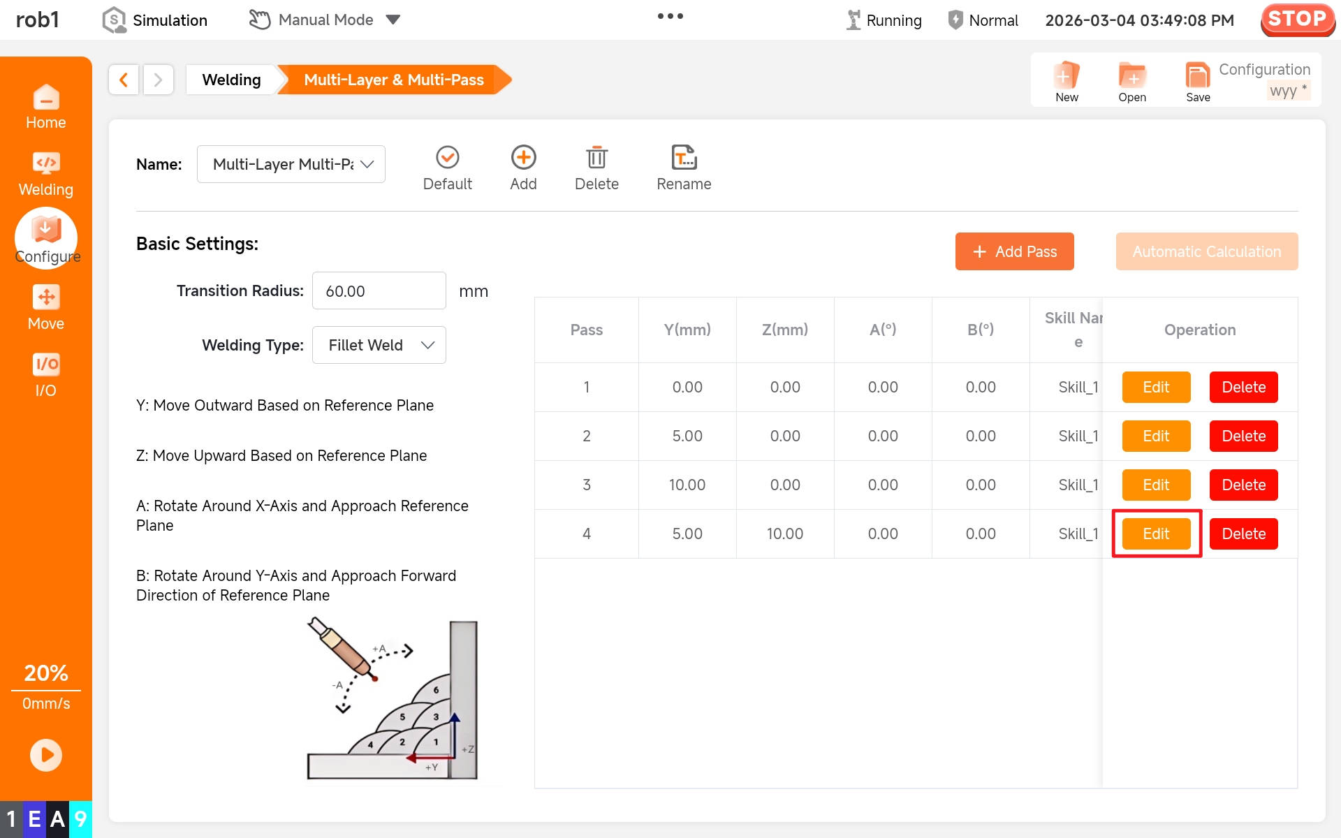
Fillet weld:
First, set the weld type to fillet weld.

When weld type is selected as fillet weld, the system will automatically recognize the reference plane based on welding torch posture. The Y axis shifts outward away from the weld, the Z axis shifts upward away from the weld, and the direction from the weld start point to the weld end point is the positive direction of the X axis. A is the angle of rotation about the X axis, with rotation about the X axis to the Y axis being positive, and B is the angle of rotation about the Y axis.

7.4 Line laser
Click [Line Laser] to enter the line laser configuration interface. The left side of this interface contains three modules: "Set Sensor," "Operate Sensor," and "Recognition Results." The right side contains two modules: "Hand-Eye Calibration" and "Configuration."


7.4.1 Set sensor
First, select the sensor manufacturer. Currently, line laser sensors from Full-V are supported. If using a Full-V sensor, select Full-V in the manufacturer field. If using a sensor from another manufacturer, select "Other" in the manufacturer field.
After selecting the sensor manufacturer, enter the sensor IP address. The following example uses the Full-V sensor. First, ensure that the sensor IP address and robot arm IP address are on the same network segment. At this point, the robot arm address is 192.168.10.51, the sensor address is 192.168.10.30, and the port number is 502.

After confirming the sensor IP address and port number, click [Connect]. The status bar will turn green, indicating a successful connection.

7.4.2 Operate sensor
After connecting the sensor, open the Full-V sensor APP interface and click [Laser Switch] to control the laser's on/off status. In the [Job Management], you can set different job numbers to configure the weld types requiring recognition.

After setting the job number, set the corresponding job number in the "Operate Sensor," and click [Set] to successfully set the job number.

7.4.3 Recognition results
Direct the laser onto the weld surface requiring recognition, ensuring that the camera can recognize the light bar. After setting the job number and sensor position, the sensor can recognize the feature points, and the recognition results are shown below.


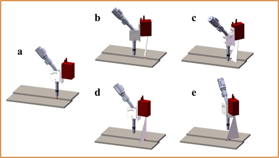
7.4.4 Hand-eye calibration
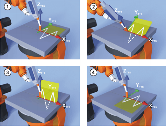
Click [Hand-Eye Calibration] to enter the following interface. First, set the calibration points by touching them with the tip of the TCP end-of-arm effector, as shown in subfigure a. Then, position the robot arm in four different attitudes to ensure that the sensor's laser beam illuminates each calibration point and the sensor successfully recognizes the calibration points, as shown in subfigures b-e. After setting the calibration points and recognition points, click on [Calculate] to complete the hand-eye calibration.

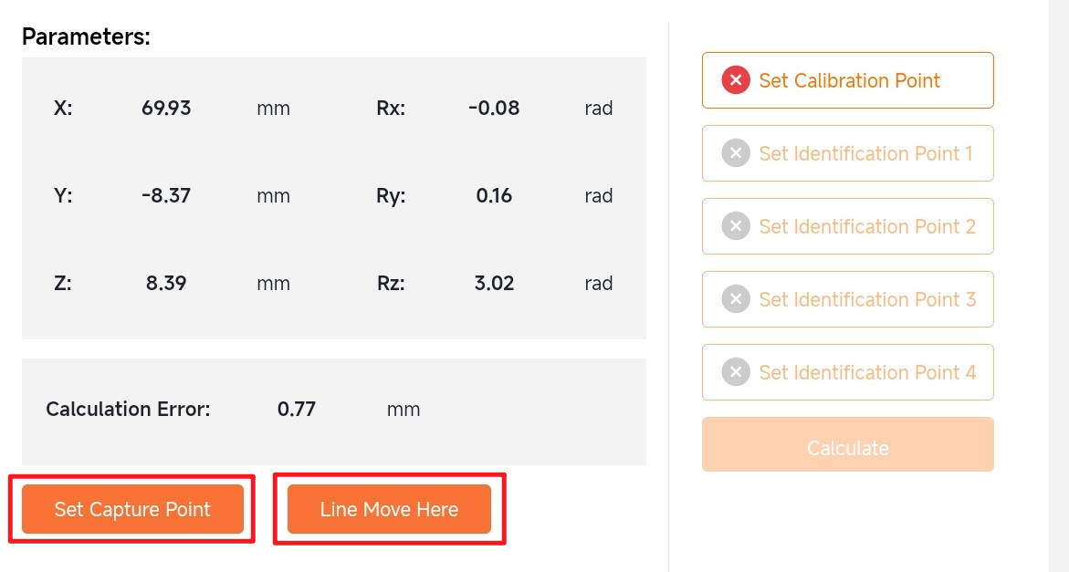
After completing hand-eye calibration, direct the laser onto the weld type corresponding to the job number while observing the sensor's recognition results. Upon successful recognition, sequentially click [Set Capture Point] -> [Line Move Here]. Long-press to automatically move the robot arm to the recognition point, verifying whether the hand-eye calibration accuracy meets operational requirements.
7.4.5 Configure
After completing hand-eye calibration, click [Configure] to enter the following interface. This interface consists of two parts: "Global Offset" and "Default Parameters."
Global offset:
X: The offset of the feature point obtained by the sensor in the x-direction relative to the robot arm base coordinate system, measured in millimeters.
Y: The offset of the feature point obtained by the sensor in the y-direction relative to the robot arm base coordinate system, measured in millimeters.
Z: The offset of the feature point obtained by the sensor in the z-direction relative to the robot arm base coordinate system, measured in millimeters.
Default parameters:
Seam Finding Hold time: The duration that the robot arm stays at the positioning point when laser positioning is used, measured in milliseconds.
Search Speed: The movement speed of the robot arm during laser search, measured in millimeters per second.

7.5 Welding configuration
Click [Configuration] -> [Welding Configuration] to enter the welding configuration interface. This interface includes two modules: “Control Mode” and “Run Prevention Prompt.”

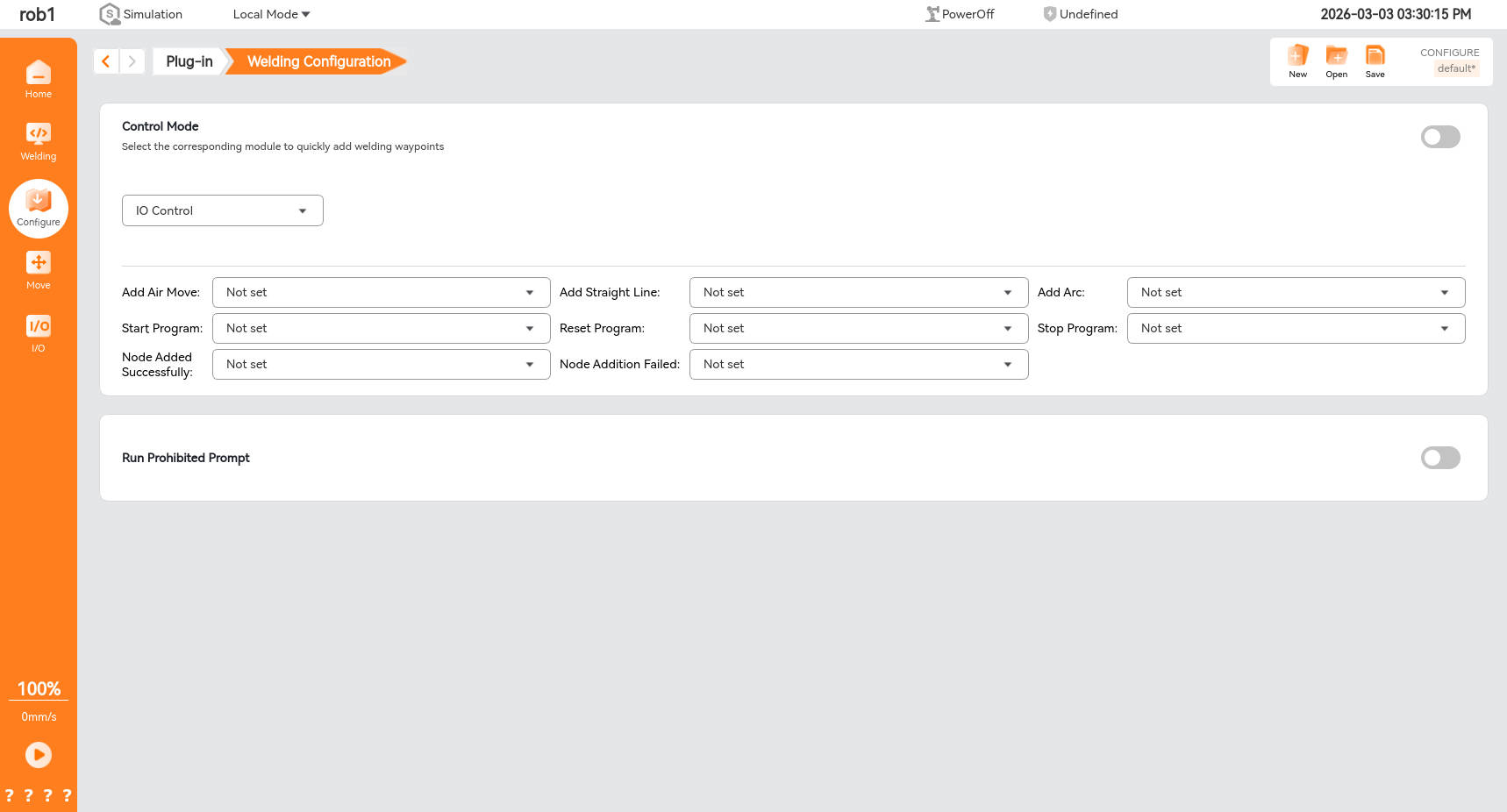
7.5.1 Control mode
To use either [I/O Control] or [Joystick Control], first turn on the control mode switch, then select the desired control mode.

7.5.2 I/O control
After selecting the control mode as [I/O Control], the route point editor below becomes editable. To add different route points, select different I/O port inputs. Connect the button to the corresponding I/O port on the control cabinet, and you can add route points by clicking the external button.

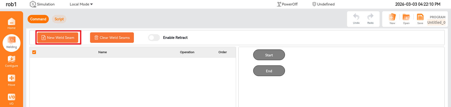
7.5.3 Creating new weld seams via I/O control
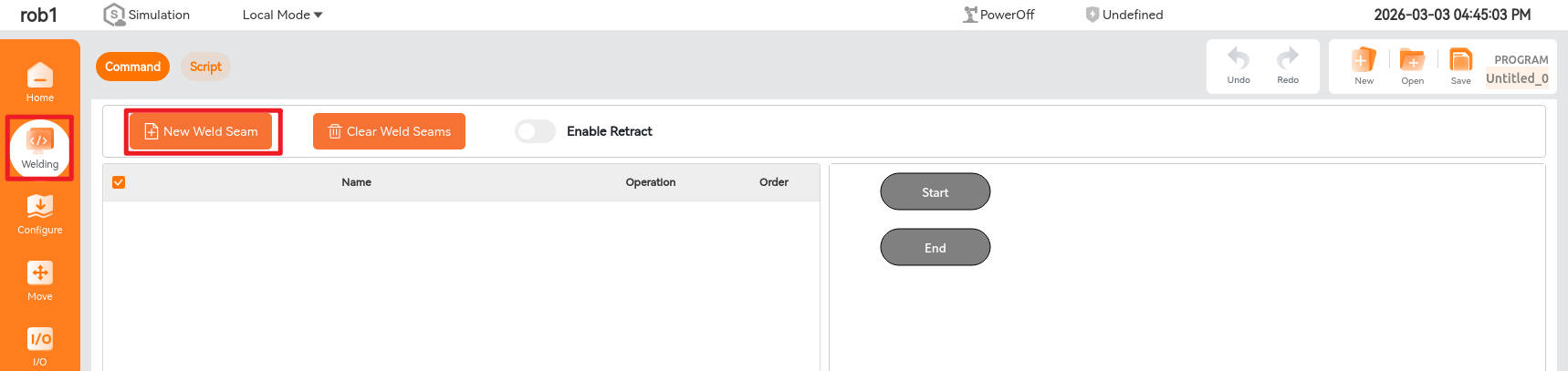
After clicking [Welding] -> [New Weld Seam], you can begin adding path points. Click the corresponding buttons for [Add Empty Point], [Add Straight Point], [Add Straight Point], and [Add Empty Point] in sequence to generate the following path. Note that path points can only be successfully added when the teach pendant interface is in the [Welding] screen.


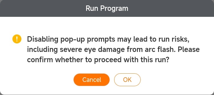
7.5.4 Run, reset, and stop programs via I/O
After establishing the welding program, click the button corresponding to the [Run Program] I/O port. A program execution prompt window will appear. Select the desired simulation mode and click [Confirm] to start the program. Clicking the button corresponding to the [Reset Program] I/O port will clear the welding program. To stop the program mid-execution, click the button corresponding to the [Stop Program] I/O port, and the robotic arm will halt its movement.

7.5.5 Operation prohibited alarm
To prevent the teach pendant from displaying the program run prompt window when the operator clicks the [Run Program] button and instead execute the program directly, enable the Run Prompt Disable switch. When the button corresponding to the [Run Program] I/O port is clicked, the teach pendant will not display the program run prompt window, and the program will begin execution immediately.

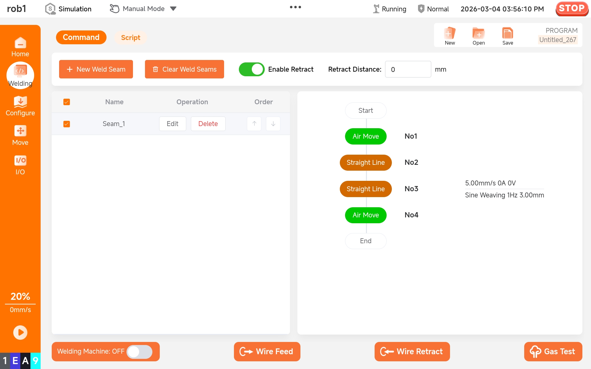
7.5.6 Enable rollback
The retract button can only be enabled after the user stops the program during the robotic arm's motion. Once enabled, the retract distance can be configured. After setting the retract distance, when the program is run again, it will retract a specified distance from the robotic arm's position when the program was last stopped. The subsequent path will then resume from this retracted point. This distance is the retract distance.

8 Welding project
8.1 Welding interface
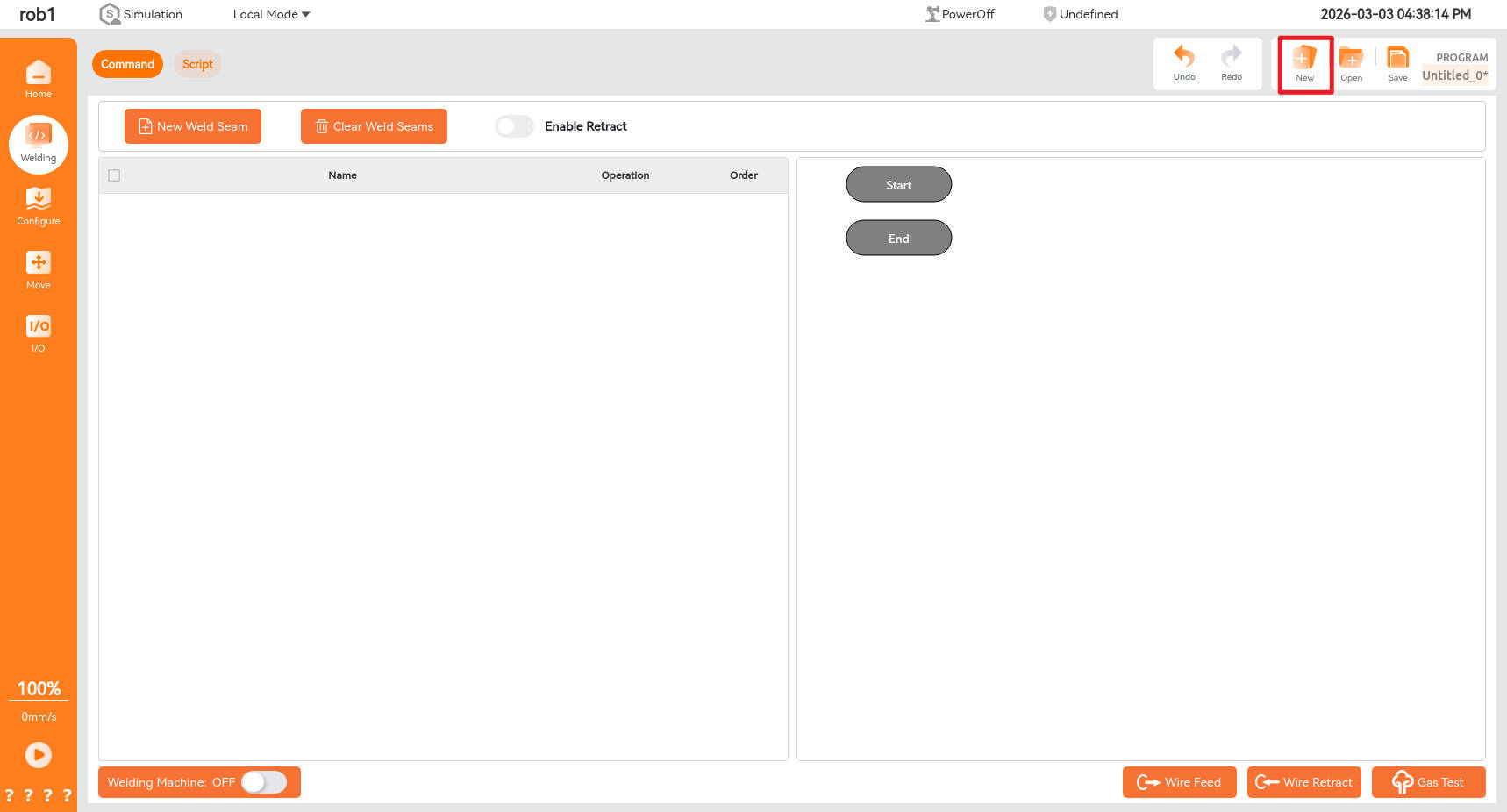
Click [Welding] to enter the welding project interface, which consists of two parts: the first part is the functional area for establishing welding projects, while the second part is the functional testing area for the welding machine.
*Welding Machine: Turn the welding machine switch to "ON" to establish communication between the welding machine and the robot arm. Once the welding route is determined, click the start program button to begin welding. *Wire Feed: Turn the welding machine switch to "ON," click [Wire Feed] button, and the welding wire will be fed through the welding torch. *Wire Retract: Turn the welding machine switch to "ON," click [Wire Retract] button, and the welding wire will be retracted through the welding torch. *Gas Test: Turn the welding machine switch to "ON," click [Gas Detection] button, and the gas will be sent out from the welding torch.

8.2 Create and open a welding project
8.2.1 Create welding project
Click the [New] button shown below to create a new welding project.
8.2.2 Open welding project
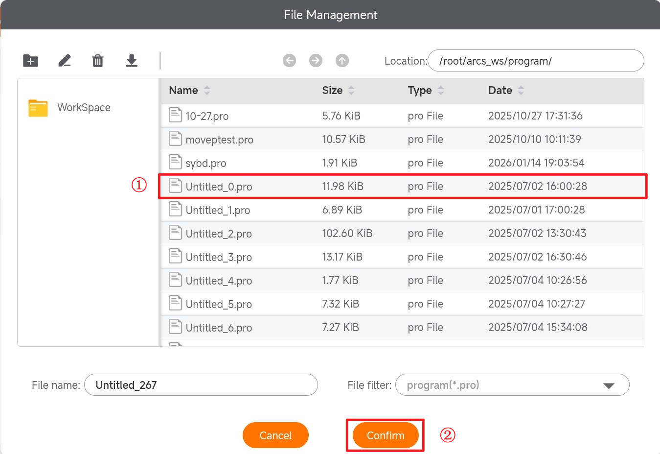
Click the [Open] button shown below to display the project options dialog box.

Click [Confirm] to display the unlock dialog box. The default password is q.

After clicking [Unlock], the following welding project list will appear. Select the project file you want to open from this list, and then click [Confirm] to open the welding project.
8.3 New weld
8.3.1 Welding project and weld
After a new welding project is created, one or more welds can be created within the welding project. As shown below, we have created welds under the welding project.

8.3.2 Edit weld
Click [Welding] -> [New Weld Seam] to enter the weld editing interface.

8.3.3 Instructions for weld node commands
The basic options on the right side of the newly created weld include weld project node commands such as empty pass, straight weld, arc weld, and fillet weld. By clicking the desired node command, you can load it into the weld. The following is an explanation of the functions of node commands:

- Air Move: Set the TCP attitude of robot obstacle avoidance points before and after welding;
- Straight Line: Set the TCP attitude for the start or end point of a straight weld;
- Arc: Set the TCP attitude for the start point, intermediate points, and end point of an arc weld;
- Boxing: Set the TCP attitude for the start or end point of a fillet weld;
- Start multi-layer and multi-pass welding: Execute the start command for multi-layer and multi-pass welding;
- End multi-layer and multi-pass welding: Execute the end command for multi-layer and multi-pass welding. Obstacle avoidance points must be added before the end point of multi-layer and multi-pass welding.
- Laser positioning: The laser beam illuminates the weld, and the positions of the weld points are recognized, obtaining their coordinates in the base coordinate system.
8.3.4 Set commanded joint attitude
Based on project requirements, click the node command to add it to the weld. Select the node command, click the [Waypoint] button, and then click [Update Position] to jump to the robot arm movement interface.

Move the robot arm to the desired attitude and click [OK] to complete the setting of commanded joint attitude.

8.3.5 Move to commanded joint attitude
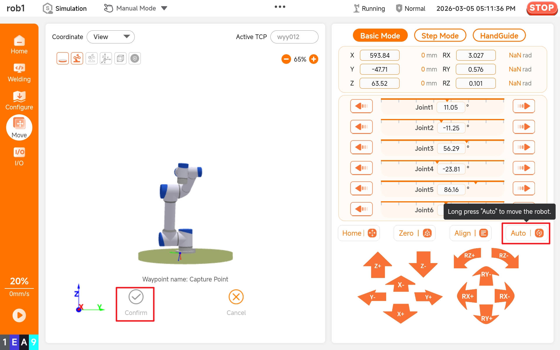
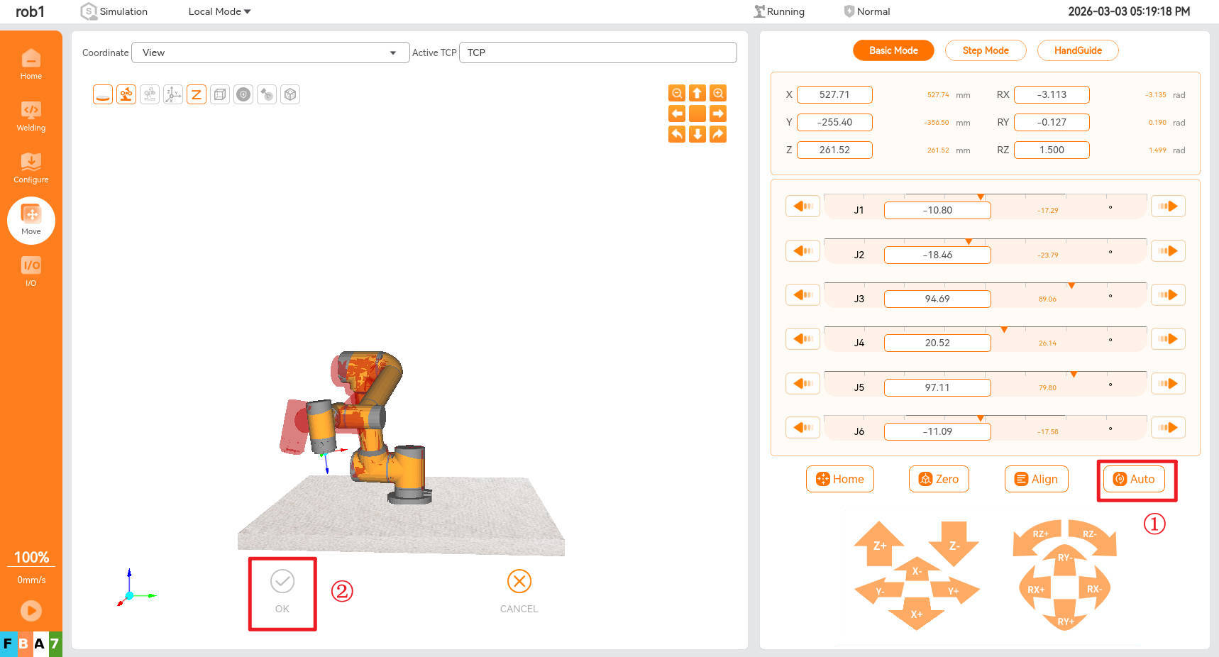
Select the node command, click the [Waypoint] button, then click [Move Joint Here] or [Move Line Here] to jump to the robot arm movement interface.

Long press the [Auto] button to have the robot arm move to the set attitude using the selected "Line" or "Joint" motion mode. After stopping the motion, click [OK] to complete moving to the commanded joint attitude.
8.4 Set weld welding parameters
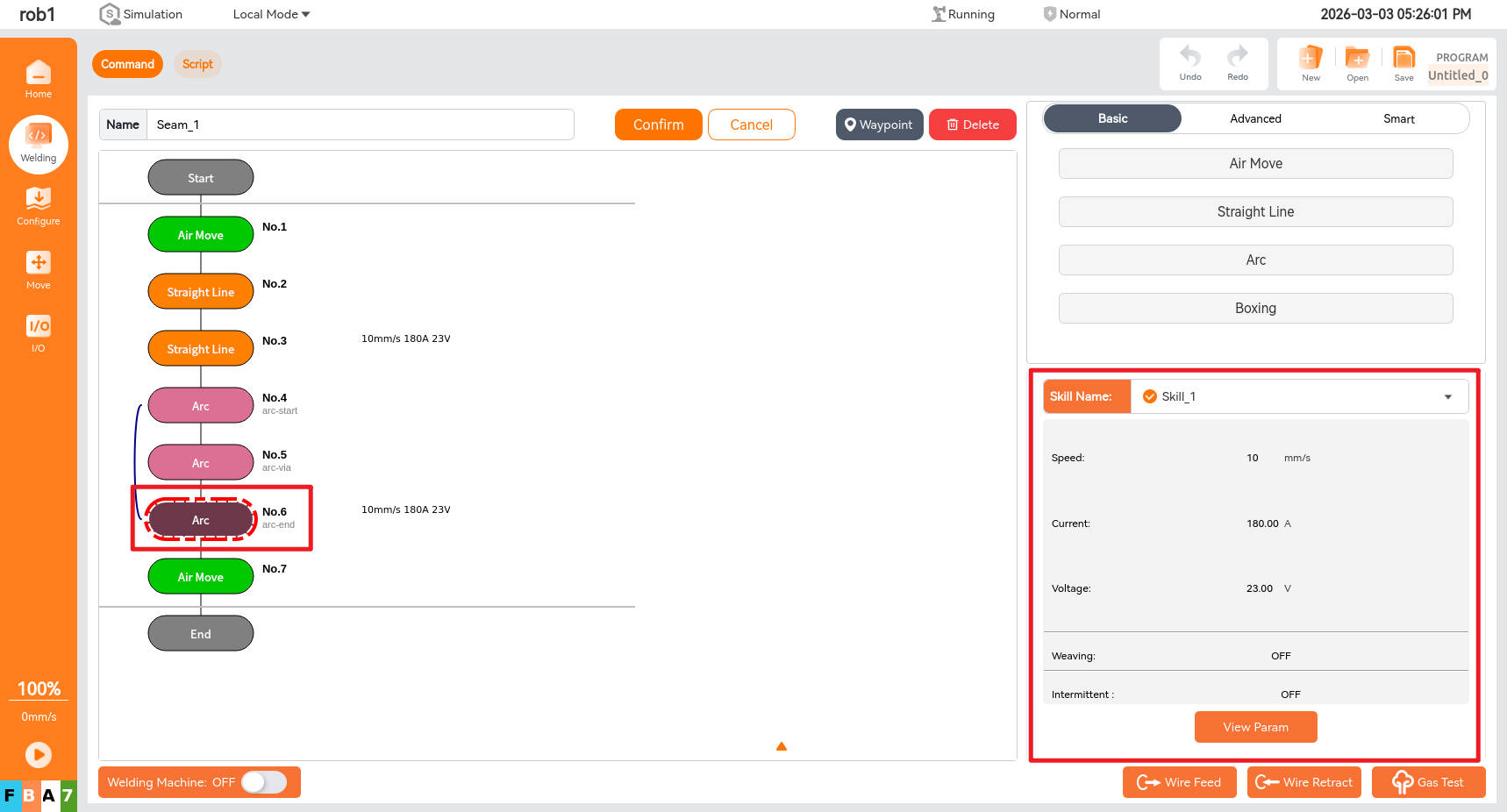
8.4.1 Location of parameter settings
Clicking the last node command for each type of weld allows you to set or view the welding parameters for that type of weld, as shown in the figure below.
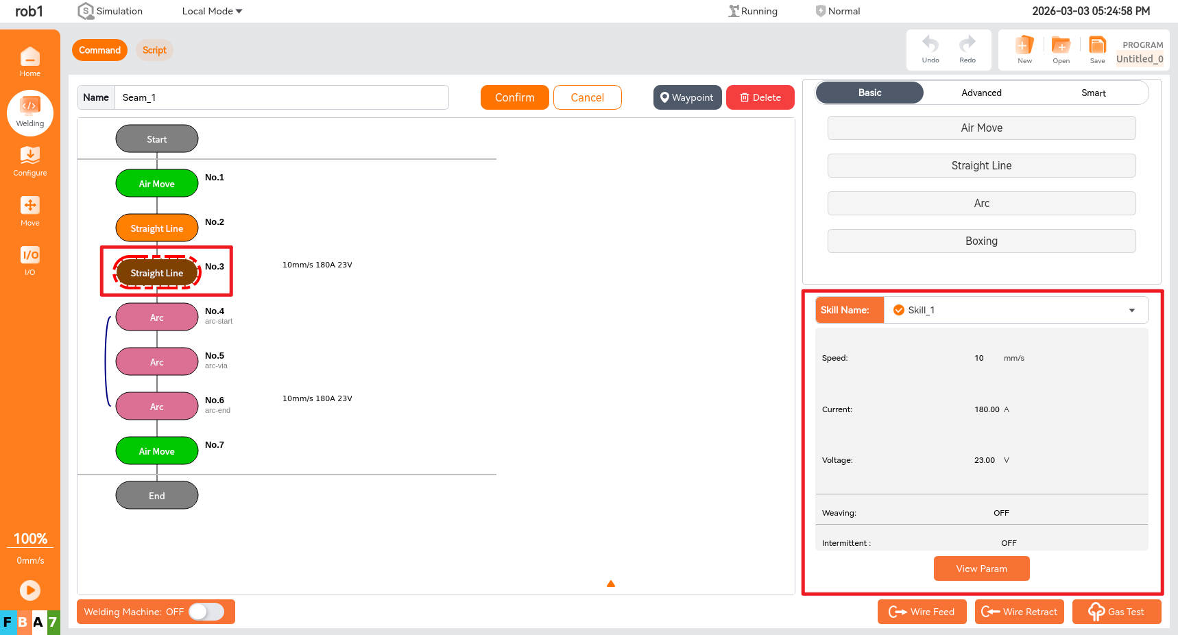
8.4.2 Selection of process parameters
Welds can be configured with two types of welding process parameters. One type consists of global welding process parameters set in the welding configuration interface, which can be used by different welds. For specific configuration methods, refer to Section 6.2.2. The other type consists of "custom process" parameters that can be configured individually for each weld. These parameters can only be used exclusively by the current weld.
- Global process parameters
Click the [Welding Skill] dropdown box to select the name of the configured process parameters, thereby completing the configuration. Clicking the parameter view button allows you to view the specific parameter configuration, but you cannot modify the parameters.


- Custom process parameters
Click the [Welding Skill] dropdown box, select [Custom Skill], then click [View Parameters] for the parameter configuration. After making modifications, click [Save].


8.5 Weld examples
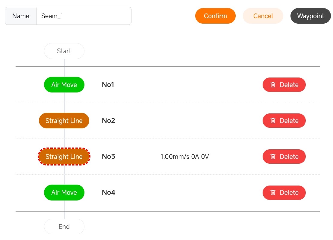
8.5.1 Example of a straight weld
8.5.2 Example of arc weld

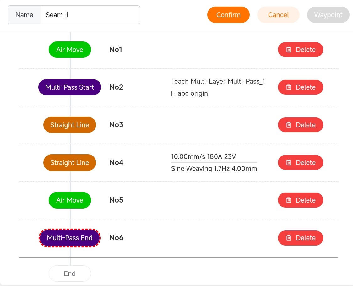
8.5.3 Example of multi-layer and multi-pass welding weld
- Single straight line
- Single arc

- Multiple lines

- Straight line and arc
- Arc and straight line

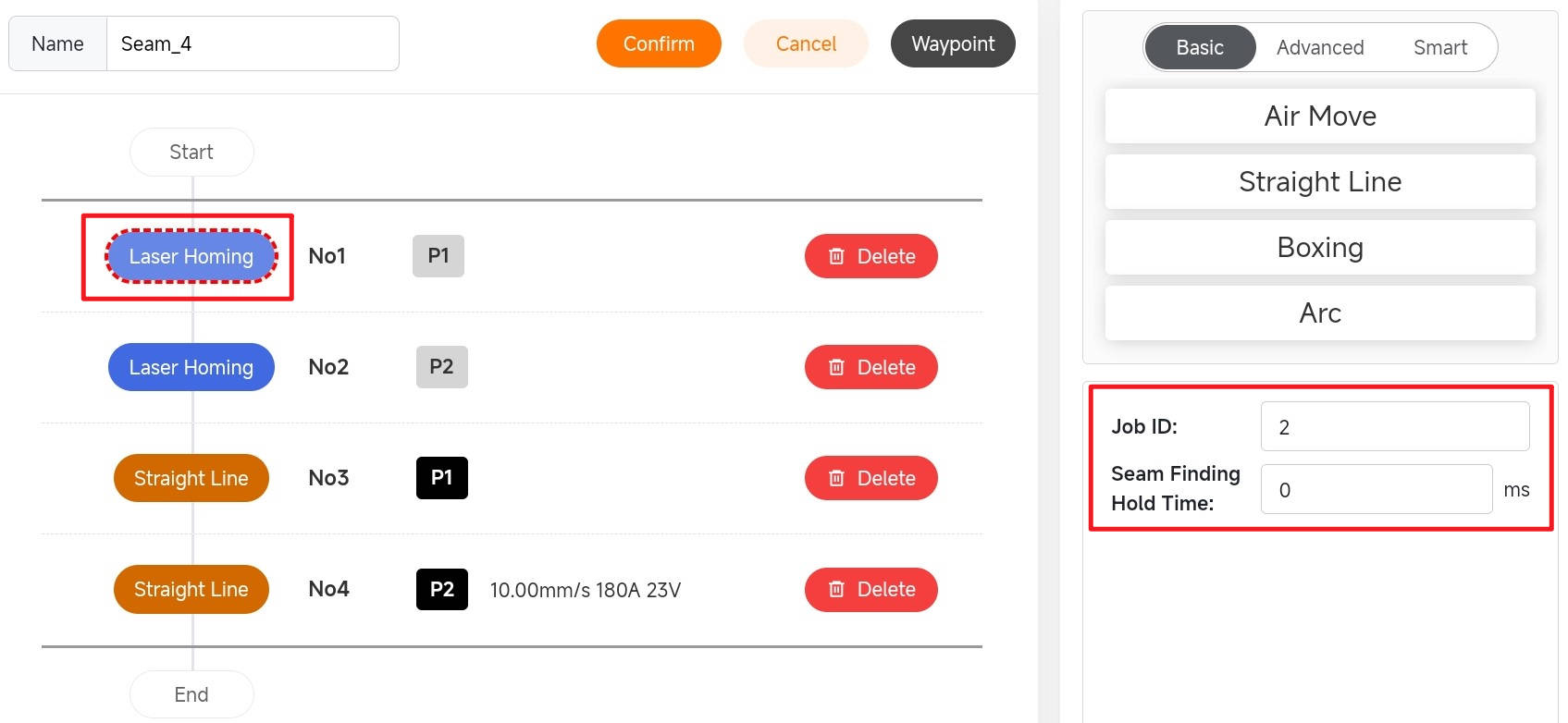
8.5.4 Example of laser positioning weld
After setting the laser positioning attitude, the job number in the laser positioning parameter is the job number of the corresponding weld type, and the holding time is the positioning holding time. The weld point obtained by positioning is stored in variable P. Taking a straight weld as an example, the start and end points of the straight weld are determined via laser positioning. Subsequently, the waypoints for the straight weld are set as P1 and P2, respectively, obtained through laser positioning.

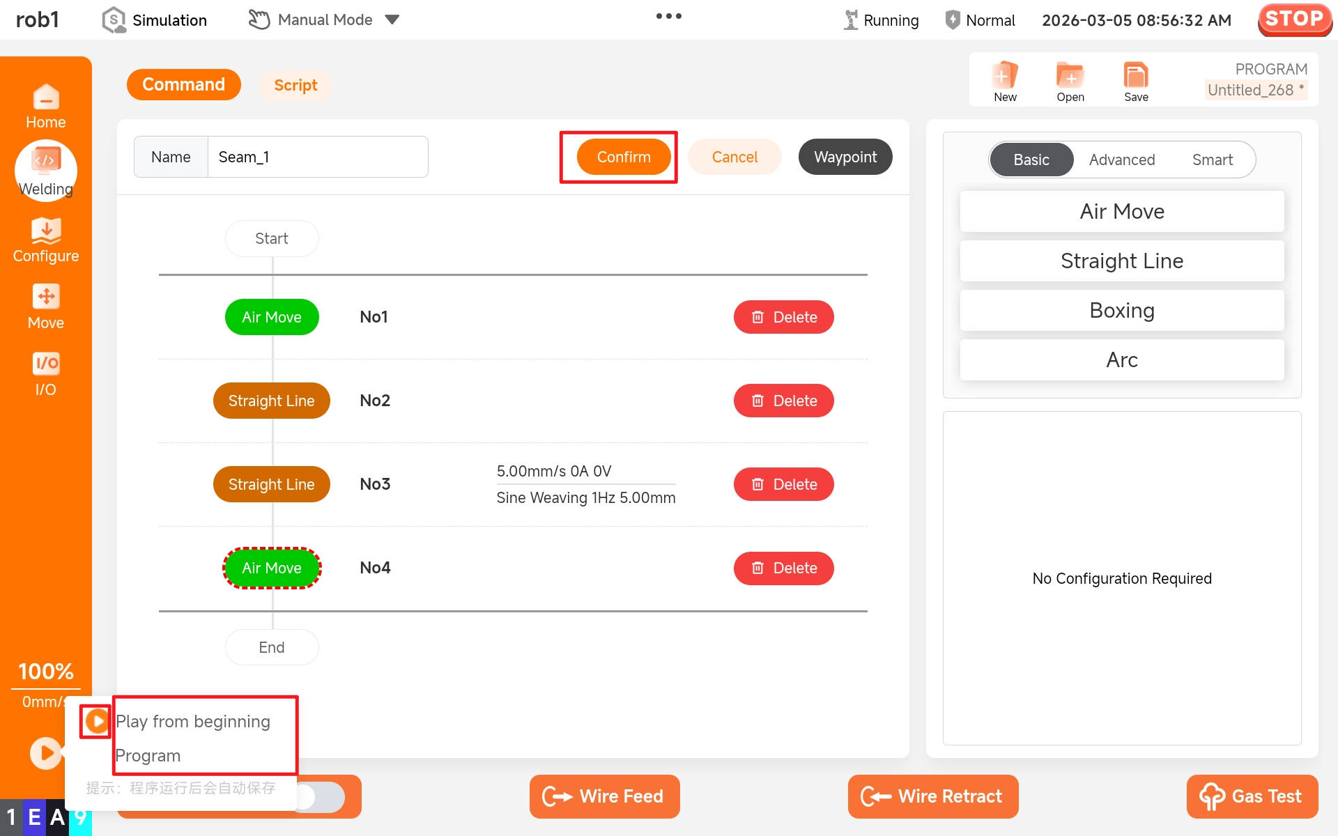
8.6 Run weld
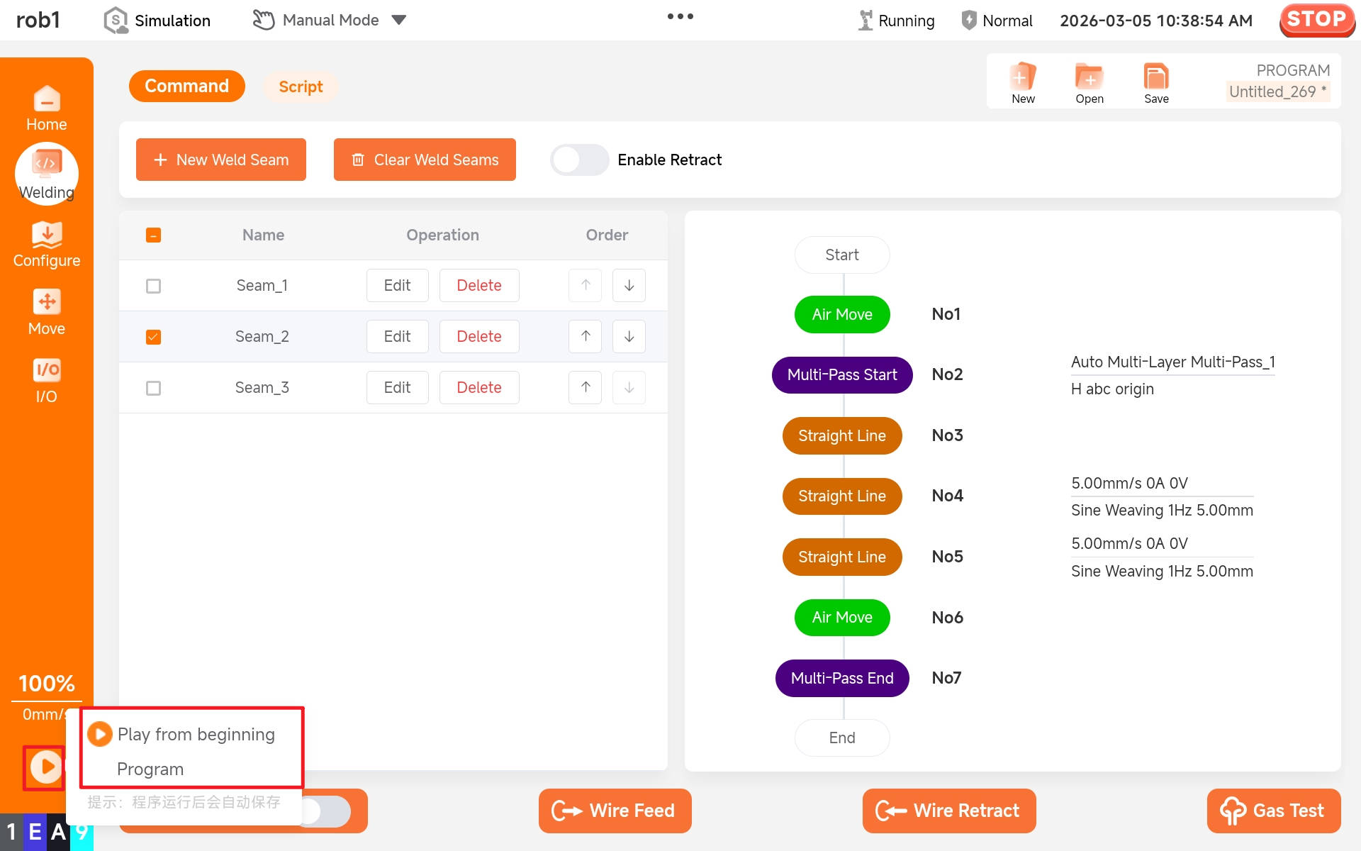
After editing the project, click the buttons in sequence: "Confirm > Play > Play from beginning Program" to run the weld.
8.7 Save weld
Click [Save] to save the weld. Multiple welds can be saved within a single project file.

8.8 Select multiple welds
A welding project may contain multiple welds. Only when the checkbox preceding a weld is selected will that weld be executed when the program starts. If multiple welds are selected, they will be executed sequentially in the order they were selected.

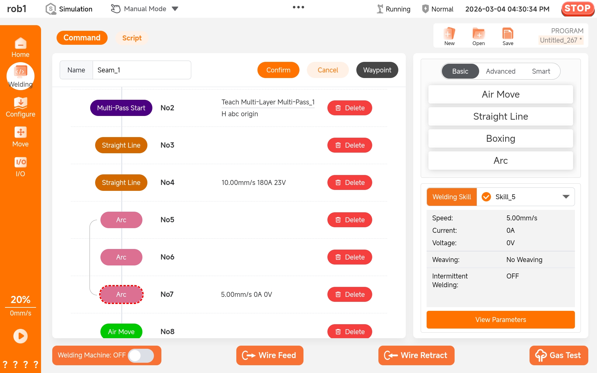
8.9 Configure multi-layer and multi-pass welding parameters
8.9.1 Load process parameters
Click the [Multi-Pass Start] node command. A parameter settings dialog will appear in the lower right corner. Select the name of the configured multi-layer and multi-pass welding process parameters from the [Multi-Pass Skill] dropdown box to complete the parameter configuration.

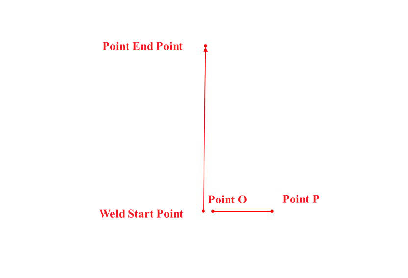
8.9.2 Configure O and P points
After completing the parameter configuration, you must also set the O and P points. For arc weld or multi-weld scenarios, enable the automatic detection of O and P points. For a single straight line, manually set the O and P points separately. Click the [Set Point O] button to enter the robot arm movement interface. Move to the desired position and click [Apply] to complete the O point setting. The P point is set in the same manner.


Setting methods of O and P points on a single straight line: The directions of O and P shall be perpendicular to the weld's progression direction. For an X-weld, the direction from the weld start point to the weld end point is the positive direction of the X axis.
8.10 Original track simulation and fast simulation
Once the welding project is established, the original track simulation and rapid simulation can be used to check whether the robot arm runs according to the user's expected track. First, click [Confirm] to activate the welding project. (The welding project will not take effect unless confirmed.)

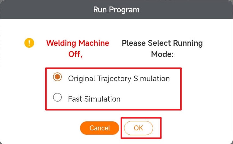
Click the "Start Program" button, and a running program selection box will pop up (the welding machine remains off during this step).
First, select original track simulation/fast simulation. If the [Fast Simulation] is selected, the robot arm will simulate the weld program track using motion parameters. If the [Original Track Simulation] is selected, the robot arm will simulate the weld program track using process parameters.

9 Link mode
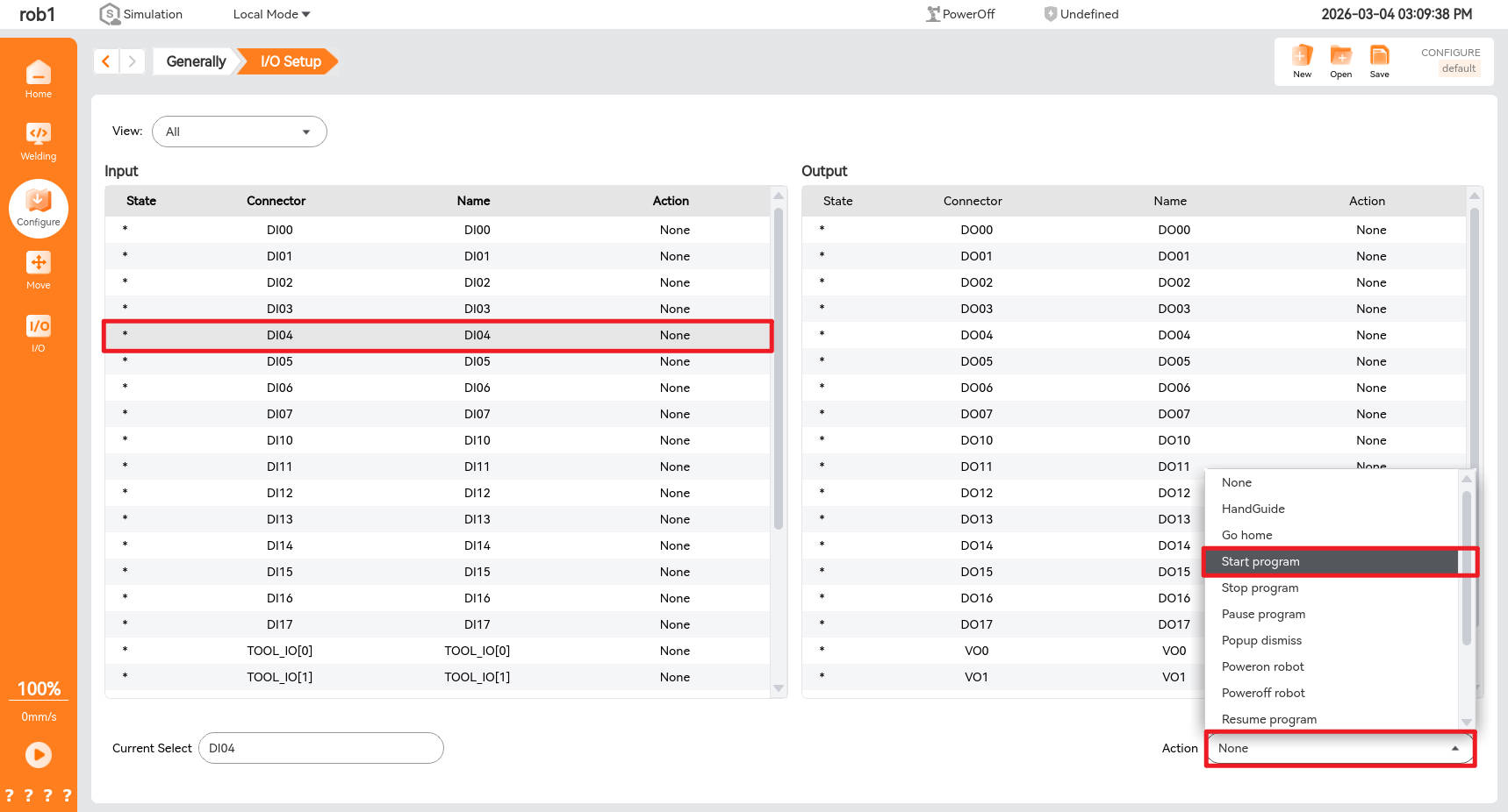
9.1 External I/O setting
Click the [Configure] shown below, and then select [I/O Setup] to enter the I/O setup interface.

Users can connect external buttons to the corresponding I/O ports of the control box and assign the function of the control box I/O port to which the button is connected on the [I/O] setup interface.
9.2 Switch to link mode
After the user has created a weld program, select the corresponding weld and turn on the welding machine switch.

As shown in the figure below, switch the teach pendant to the link mode.

At this time, the robot arm cannot be controlled; the welding project can only be started by pressing an external button.

10 Common Questions
Question: How to handle when the welding IO signal function is ineffective?
Solution:
Check if the IO wiring is secure.
Check if the function settings of the Megmeet welding machine are correct.
The main function table of the welding machine is as follows:
Code Function Name Unit Adjustment Range Step Default Value FA0 Robot / Group Control Function Switch / OFF: Manual Welding Mode
GP: Manual Group Control Mode
OB: Robot Mode/ OFF FA1 Proximity Control Switch / OFF: Proximity control disabled
ON: Proximity control enabled/ OFF FA2 JOB Switch Time s 0.01~9.99 0.01 0.1 FA3 Welding Power Supply MAC ID / 0~63 1 ABB: 20
CANOPEN: 10
Others: 10FA4 Robot Search Success Signal Polarity Selection / OFF: Output low level / "1"
ON: Output high level / "0"/ OFF FA5 Welding Power Supply Ready Signal Polarity Selection / OFF: Output low level / "1"
ON: Output high level / "0"/ OFF FA6 Robot Arc Start Success Signal Polarity Selection / OFF: Output low level / "1"
ON: Output high level / "0"/ OFF FA7 Robot Setpoint Signal Type Selection / OFF: Welding power supply receives wire feed speed setpoint
ON: Welding power supply receives current setpoint/ OFF FA8 High Voltage Search Function Enable Switch / OFF: High voltage search disabled
ON: High voltage search enabled/ OFF FA9 Robot Communication Protocol Option / See Table 4-4 / OFF (Analog Communication) FAA Robot Digital Communication Baud Rate Option / 0: 125kbps
1: 250kbps
2: 500kbps1 0 FAB Robot Ready Reverse Function Switch / OFF: Reverse function disabled
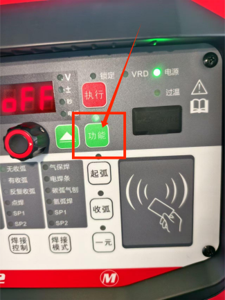
ON: Reverse function enabled/ OFF FAC Arc Tracking Current Filter Coefficient / 0~63 1 20 Steps for checking the functions of the welding machine:
- Press and hold the function key.
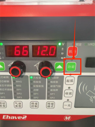
- Enter the welding machine's function mode, and rotating the left knob allows you to switch and view the welding machine's configurations.
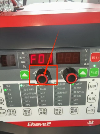
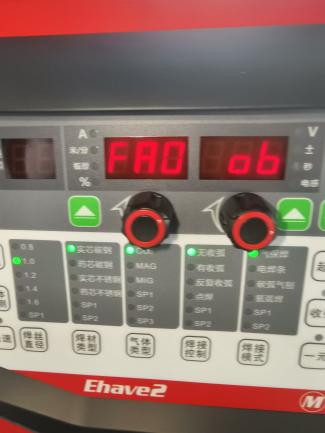
- Increase the rotation angle, turn the knob until FA0 is displayed on the left side of the screen, then check if "ob" is displayed on the right side of the screen. If it is displayed, it is normal.
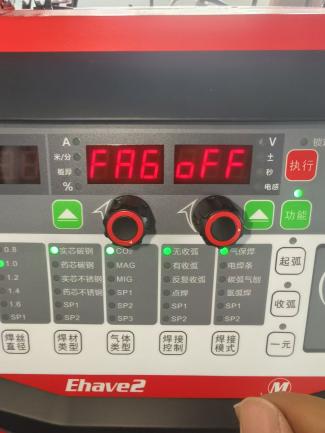
- Increase the rotation angle, turn the knob until FA6 is displayed on the left side of the screen, then check if "oFF" is displayed on the right side of the screen. If it is displayed, it is normal.
- Increase the rotation angle, turn the knob until "FA9" is displayed on the left side of the screen, then check if "oFF" is displayed correspondingly on the right side. If it corresponds, it is normal.
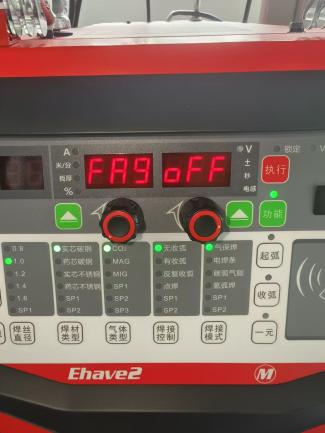
- Click the function to exit the function mode, and the test is completed.
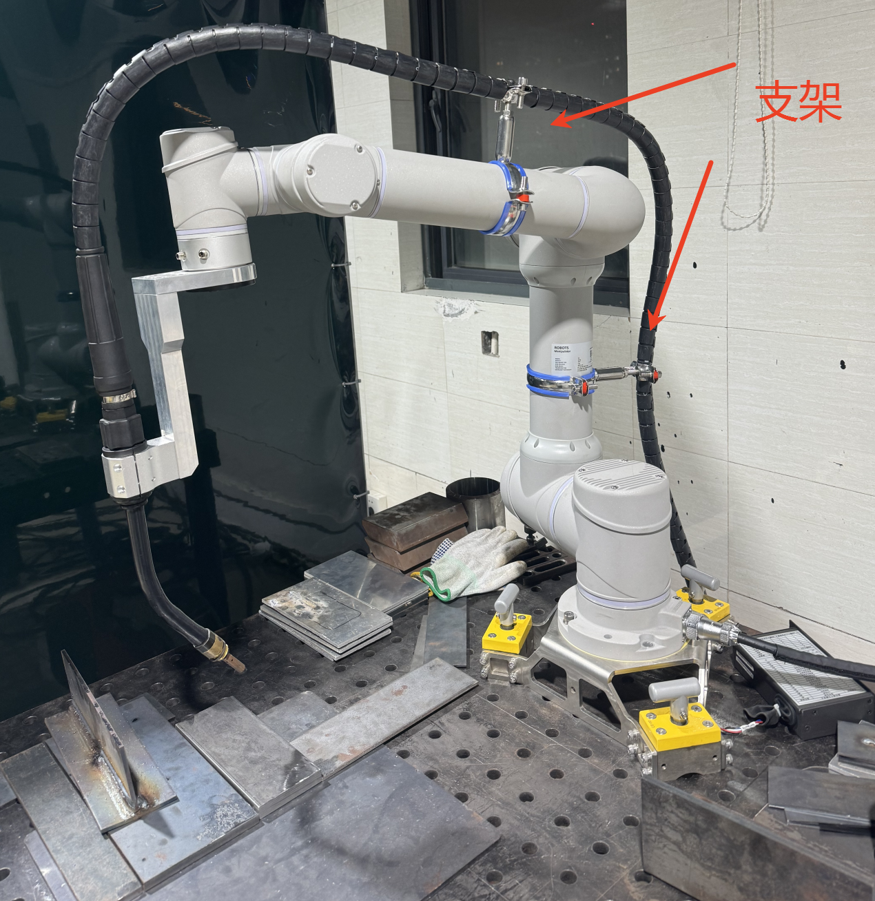
Question: How to handle abnormal arc breakage during the welding process? Solution:
Wire feeding resistance may cause unsmooth wire feeding. Please straighten out the welding torch cable without twisting it, as shown in the figure below:
Check if the used contact tip is clogged.
Question: How to handle the deviation in the control accuracy of the output voltage and current of the welding machine?
Solution:
Check whether the correct corresponding welding machine model is selected (different welding machines and models have different voltage and current curve relationships. For example, for the Megmeet 500 model, the analog voltage 1 of the control cabinet = actual welding machine current / 55, and the analog voltage 2 of the control cabinet = actual welding machine voltage / 5).
Check if the welding machine is in the synergic state. If it is in the synergic state, please turn off the synergic function and use the separate mode to control the operation of the welding machine.
Check whether there is a phase loss in the corresponding three-phase electrical wiring.
Question: How to solve the problem of porosity in welding?
Solution:
- Perform an air supply check on the protective gas to ensure that the gas supply pipeline is unobstructed.
- Check the dry extension, which is generally 10-15 times the diameter of the welding wire. Within this range, the shielding gas can protect the welding process from excessive oxygen participating in chemical reactions, thus preventing the formation of nitrogen pores.