Product Manual for AUBO Haina Series Composite Robot
1 About this manual
1.1 Copyright and disclaimer
Version information
v1.0.0
The User Manual will be subject to regular check and revision, and updated content will appear in new versions. The content or information in this manual is subject to change without prior notice. AUBO (Beijing) Robotics Technology Co., Ltd. is not responsible for any errors or omissions that may appear in this manual, or for any accidental or indirect damages resulting from the use of this manual and the products described herein. Please read this manual before installing and using the product. Please keep this manual properly for reading and reference at any time. All figures in this manual are for illustrative purposes only. The actual product received shall prevail. This manual is the exclusive property of AUBO (Beijing) Robotics Technology Co., Ltd. It may not be photocopied, reproduced in whole or in part, or converted into any other form without the written permission of AUBO (Beijing) Robotics Technology Co., Ltd.
Copyright © 2015-2026 AUBO All rights reserved.
This is the User Manual for the mobile collaborative robot. It is intended to provide users with guidance for the safe and effective use of the mobile collaborative robot. Please be sure to read this manual carefully before use. All figures in this manual are for reference only. The actual product shall prevail.
All safety information contained in this manual shall not be considered a guarantee by AUBO (Beijing) Robotics Technology Co., Ltd. Personal injury or equipment damage caused by the operator may still occur even if all safety instructions are followed.
AUBO (Beijing) Robotics Technology Co., Ltd. is committed to continuously improving the reliability and performance of its products and therefore reserves the right to upgrade its products without prior notice. AUBO (Beijing) Robotics Technology Co., Ltd. strives to ensure the accuracy and reliability of the content in this manual, but is not responsible for any errors or omissions. The company is not liable for any personal injury or equipment damage caused by the improper use of this equipment not in accordance with the manual.
1.2 Scope of application
This manual is the product instruction document for AUBO Haina series composite robots. It is applicable to the following products: AMR-300-S。
This manual is for operation guidance only and does not serve as a guarantee of product functions and performance. For specific product functions and performance specifications, please refer to the actual product.
1.3 How to use this manual
Please use this manual when installing the composite robot.
1.4 Target audience
This manual is intended for users of the AUBO Haina series composite robot (wireless version), such as customers, programmers, technical support personnel, and operators.
1.5 Operation prerequisites
Readers should have a basic understanding of the following: None
1.6 Related documents
- Operation Manual for AUBO Haina Series
- Composite Robot (Wireless Version) ARCS Teach Pendant Software User Manual
2 Safety
2.1 Introduction
This section describes the safety principles and regulations that should be followed for operating the robot or robotic system. Integrators and users must read this manual carefully. The content marked with warning signs needs to be fully understood and strictly followed. Due to the complexity and high risk of the robotic system, users need to be fully aware of the operational risks and strictly abide by and implement the specifications and requirements in this manual.
2.2 Safety warning signs
The safety-related content in this manual is illustrated using the following warning signs. The descriptions of the warning signs in the manual indicate important information that must be followed.
| Sign | Description |
|---|---|
 | A potentially hazardous electrical situation which, if not avoided, could result in death or serious injury. |
 | A potentially hazardous electrical situation which, if not avoided, could result in personal injury or serious equipment damage. |
 | A potentially hazardous situation which, if not avoided, could result in minor personal injury or equipment damage. Matters marked with this symbol may, depending on the specific circumstances, sometimes have the potential for serious consequences. |
 | A situation which, if not avoided, could result in personal injury or equipment damage. Matters marked with this symbol may, depending on the specific circumstances, sometimes have the potential for serious consequences. |
2.3 Safety precautions
2.3.1 Overview
This manual contains safety measures to protect operators and prevent equipment damage. Users must read all relevant content of the manual to fully grasp the safety precautions. This manual has covered various usage scenarios as much as possible. However, due to the multiple variables in actual situations, it cannot exhaust all prohibited operations and potential risk scenarios.
2.3.2 Usage notes
The following basic information needs to be understood and followed before starting the robot or robotic system for the first time. Other safety-related information is introduced in other parts of the manual.
| Warning | precautions |
|---|---|
| Please be sure to install the robot and all electrical equipment in accordance with the requirements and specifications in this user manual. 2. Initial tests and inspections on the robot and its protective system are required before the first use and commissioning. 3. Before starting the system and equipment for the first time, be sure to check whether the equipment and system are complete, safe to operate, and free of any damage. During this inspection, it is necessary to observe compliance with national or regional production safety regulations, and all safety features must be tested. 4. The user must check and ensure that all safety parameters and user programs are correct, and that all safety features are functioning properly. Personnel qualified to operate the robot are required to check each safety feature. The robot can only be started after it has passed comprehensive and careful safety tests and reached the required safety level. 5. The robot must be installed and commissioned by qualified professionals in accordance with installation standards. 6. When the robot installation and construction are complete, a comprehensive risk assessment must be conducted again and documented. 7. Safety parameters must be set and changed by authorized personnel, and passwords or isolation measures must be used to prevent unauthorized personnel from changing or setting them. After the safety factor is modified, the relevant safety features need to be analyzed. 8. In case of an accident or abnormal operation, the emergency stop switch can be pressed to stop the robot's movement. 9. The joint modules of the AUBO iH series robot are equipped with brakes to maintain the robot's posture during a power outage. Do not frequently turn the power supply on and off. It is recommended that the interval between power cycles be greater than 10s. 10. The AUBO iH series robot has a collision detection function. When an external force on the powered-on robot exceeds the normal force range set by the user for safety, the robot will stop automatically to prevent damage or injury to the robot or operator from collision. This feature is specially designed for the safety of human-robot collaboration in the AUBO iH series robot. However, it requires the robotic system to be within its normal operating range and to be used with AUBO series AGV products. If the users develop their own controllers, the robot will not have the above functions. The user is solely responsible for any hazardous consequences arising therefrom. 11. The robot body and control cabinet generate heat during operation. Do not operate or touch the robot while it is working or immediately after it has stopped. 12. Turn off the power supply and wait for one hour for the robot to cool down. |
| 1. Ensure that the robot's arm and tool are correctly and securely installed. 2. Ensure that the robot's arm has enough space to move freely. 3. Do not use the robot if it is damaged. 4. Do not connect safety devices to normal I/O interfaces; only use safety interfaces. 5. Ensure correct installation settings (e.g., installation angle of the robot body, weight in TCP, TCP offset, safety configuration, etc). Save the installation file and load it into the program. 6. Tools and obstacles must not have sharp corners or pinch points. Ensure that everyone's head and face are outside the robot's reachable range. 7. Pay attention to the robot's movement when using the teach pendant software. 8. Any impact will release a large amount of kinetic energy, which is much higher than that in high-speed and high-payload situations. 9. Connecting different machines may increase existing hazards or create new ones. Always perform a comprehensive risk assessment of the entire installation. When different safety and emergency stop performance levels are required, always select the highest level. Always read and understand the manuals for all equipment used in the installation. 10. Never modify the robot. Modifications to the robot may create hazards that the integrator cannot foresee. Authorized robot reconfiguration must be performed in accordance with the latest version of all relevant service manuals. If the robot is changed or modified in any way, AUBO (Beijing) Robotics Technology Co., Ltd. disclaims all liability. 11. Before transporting the robot, the user needs to check the insulation and protective measures. 12. When handling the robot, comply with the transportation requirements and handle it with care to avoid collisions. |
| 1. When the robot is connected to or working with machinery that could cause damage to the robot, it is strongly recommended to check all robot functions and programs separately. It is recommended to use temporary waypoints outside of other mechanical workspaces to test the robot program. 2. AUBO (Beijing) Robotics Technology Co., Ltd. is not liable for any damage to the robot or personal injury caused by programming errors or improper operation on the robot. 3. Do not expose the robot to permanent magnetic fields. Strong magnetic fields can damage the robot. 4. Failure to correctly place or secure the load may cause the load to fall or the robot to tip over. 5. Ensure that the load is placed according to specifications and secured correctly. 6. The robot cannot observe descending stairs and holes in the floor. Please mark stairs and holes as forbidden zones on the map and update the map in a timely manner. 7. Please maintain the integrity of the AGV platform. If application development requires drilling, it may cause damage to the robot's electrical equipment. 8. Do not hit the robot's lidar shell to prevent radar wear or even damage, which could lead to the robot losing its autonomous driving capability. 9. Do not step on or place heavy objects on the robot's plastic shell to prevent shell damage. 10. Please use the provided key switch to open the robot's latch. Do not use external force to break the latch. |
2.3.3 Personnel safety
During operation of the robotic system, the safety of the operators must be ensured first. The following are general precautions. Please take appropriate measures to ensure the safety of the operators.
| Warning | precautions |
|---|---|
| 1. All personnel who use the robotic system shall be trained through the training courses organized by AUBO (Beijing) Robotics Technology Co., Ltd. Users must ensure that they have a full understanding of safe and standard operating procedures and are qualified to operate the robot. For training details, please contact our company at support@our-robotics.com. 2. All personnel using the robotic system shall not wear loose clothing or jewelry. Please ensure long hair is tied back when operating the robot. 3. While the equipment is running, even if the robot appears to have stopped, it may be in a state of imminent motion, waiting for a start signal. Even in this state, the robot shall be considered active. 4. During use of the wireless teach pendant, operational errors may occur if you are wearing gloves, so be sure to remove them before operation. 5. In emergency and abnormal situations, such as when a person is trapped or surrounded by a collaborative robot, force the joints to move by pushing or pulling the robot arm firmly. Manually moving the robot arm without power is limited to emergency situations and may damage the joints. 6. The high-speed rotating parts of the robot (universal wheels or driving wheels) can cause personal injury. 7. Do not over-rely on the robot's autonomous obstacle avoidance function. Please proactively avoid the operating robot. |
2.4 Responsibilities and specifications
The AUBO AMR series robot can be combined with other equipment to form a complete machine, but it is not complete by itself. Therefore, the information in this manual does not cover how to comprehensively design, install, and operate a complete robot, nor does it exhaust all possibilities that could affect the safety of the peripheral equipment of this complete system. The safety of a complete robot installation depends on how the robot is integrated. The integrator must conduct a risk assessment for the design and installation of the complete system in accordance with the laws, regulations, safety specifications, and standards of their country. The risk assessment is one of the most important tasks that the integrator must complete. The integrator can refer to the following standards to perform the risk assessment process.
- ISO 12100:2010 Safety of Machinery - General Principles for Design - Risk Assessment and Risk Reduction
- ISO 10218-2:2011 Robots and Robotic Devices - Safety Requirements for Industrial Robots - Part 2: Robot Systems and Integration
- RIA TR R15.306-2014 Technical Report for Industrial Robots and Robot Systems - Safety Requirements - Task-based Risk Assessment Methodology
- ANSI B11.0-2010 Safety of Machinery; general Requirements and Risk Assessment
The integrator of the AUBO robot is required to fulfill the following responsibilities, including but not limited to:
- Conduct a comprehensive risk assessment on the complete robotic system;
- Confirm that the design and installation of the entire system are correct;
- Provide training to users and staff;
- Create operating specifications for the complete system and clarify the instructions for use;
- Establish appropriate safety measures;
- Use appropriate methods to eliminate hazards or minimize all hazards to an acceptable level during final installation;
- Communicate residual risks to the end user;
- Mark the integrator's logo and contact information on the robot;
- Archive relevant technical documents.
To consult applicable standards and legal guidelines, please visit the website: www.aubo-robotics.cn.
All safety information contained in this manual shall not be considered a guarantee by AUBO (Beijing) Robotics Technology Co., Ltd. Personal injury or equipment damage caused by the operator may still occur even if all safety instructions are followed.
AUBO (Beijing) Robotics Technology Co., Ltd. is committed to continuously improving the reliability and performance of its products and therefore reserves the right to upgrade its products without prior notice. AUBO (Beijing) Robotics Technology Co., Ltd. strives to ensure the accuracy and reliability of the content in this manual, but is not responsible for any errors or omissions.
2.5 Hazard identification
The risk assessment should consider all potential contact between the operator and the robot during normal use, as well as foreseeable misuse. The operator's neck, face, and head shall not be exposed to avoid contact. Using the robot without peripheral safety guards requires a prior risk assessment to determine if the associated hazards pose an unacceptable risk, for example:
- Potential hazards from using sharp end effectors or tool connectors;
- Potential hazards from handling toxic or other harmful substances;
- The risk of the operator's fingers being pinched by the robot base or joints;
- The hazard of being struck by the robot;
- The hazard of the robot or the tool connected to the end not being securely fastened;
- The hazard of impact between the robot payload and a solid surface.
The integrator must measure such hazards and their associated risk levels through a risk assessment, and must identify and implement corresponding measures to reduce the risks to an acceptable level. Please note that other significant hazards may exist for specific robot equipment.
By combining the inherent safety design measures applied to AUBO robots with the safety specifications or risk assessments implemented by the integrator and end-user, the risks associated with the collaborative operation of the AUBO series robots are reduced to a reasonably practicable minimum. This document serves to communicate any residual risks present before the robot's installation to the integrator and end-user. If the integrator's risk assessment determines that there are hazards in their specific application that may pose an unacceptable risk to the user, the integrator must take appropriate risk reduction measures to eliminate or minimize these hazards until the risk is reduced to an acceptable level. It is unsafe to use the robot before appropriate risk reduction measures, if required, have been taken.
If the robot is installed for non-collaborative use (e.g., when using hazardous tools), the risk assessment may conclude that the integrator needs to connect additional safety devices (e.g., a safety start device) during its programming to ensure the safety of personnel and equipment.
2.6 Emergency handling
2.6.1 Emergency stop device
This is a secondary protective device. If multiple emergency stop buttons need to be connected, this must be included in the risk assessment of the robot application. The emergency stop button complies with the requirements of IEC 60947-5-5.
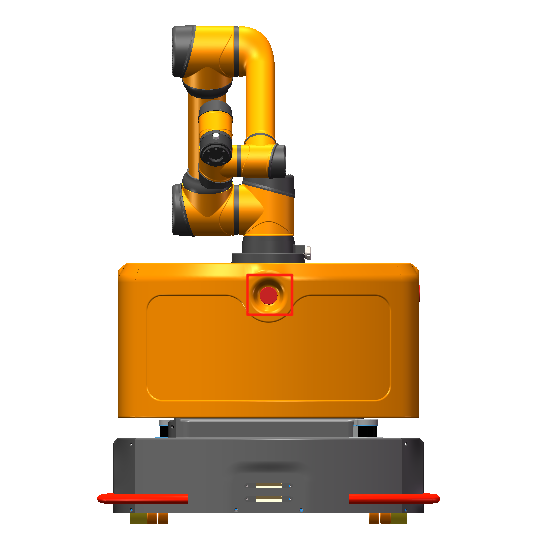
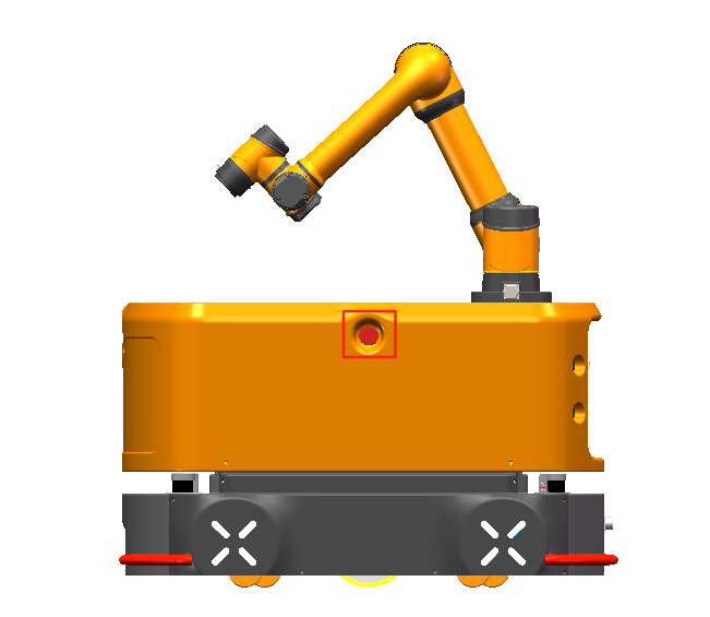
The AGV chassis is equipped with external emergency stop button ports on the right side, front, and left side, which the integrator or user can use according to the actual situation.

| Warning | Instructions |
|---|---|
| If a tool or device connected to the end poses a potential threat, it must be integrated into the system's emergency stop circuit. Failure to comply with this warning may result in death, serious personal injury, or significant property damage. |
| 1. The Emergency Stop button is for emergency use only and must not be used to stop the robot's operation. 2. When the Emergency Stop button is pressed, the robot immediately stops all motion. |
2.6.2 Recovering from an emergency state
All push-button type emergency stop devices have a "lock" function. This "lock" must be released to end the device's emergency stop state.
Rotate the Emergency Stop button to release the "lock".
| Warning | Instructions |
|---|---|
| Recovering from an emergency stop state is a simple but very important step, which can only be performed after ensuring that all hazards in the robotic system have been completely eliminated. |
2.6.3 Forced emergency movement of joints
In rare cases, it may be necessary to move one or more robot joints during a power failure or in an emergency where you do not want to use the power supply. This can be done by forcing the robot joints to move using the following method:
Forced back-driving: Push or pull the robot arm firmly to force the joints to move.
| Warning sign | Descriptions |
|---|---|
| Forcibly moving the robot arm manually is limited to emergency situations and may damage the joints. |
2.6.4 Over-force safety protection of collaborative robot
The robot body is equipped with an over-force safety protection feature. When the robot body is powered on and stationary, if an operator or other object accidentally collides with the robot body and the collision force exceeds the safety threshold, the robot body will move passively in the direction of the collision force. This feature can reduce injuries to operators and damage to other objects and the robot body in the event of a collision.
| Warning | Instructions |
|---|---|
| This feature can reduce collision damage. A risk assessment is required when this feature is used for other purposes. |
2.6.5 Collision protection
The robot body is equipped with a collision protection feature. During robot body operation, if an operator or other object accidentally collides with the robot body and the collision force exceeds the safety threshold, the robot body will enter a collision protection state. Different post-collision handling strategies can be set through the host computer. For details on post-collision measurements, see the table below. This feature can reduce injuries to operator and damage to other objects and the robot body in the event of a collision, while also saving time on restarting the program, improving work efficiency. The safety threshold for collision force can be changed by setting the collision level.
2.6.6 Over-force safety protection of collaborative robot
The overall safety system of the mobile collaborative robot includes two features: overall safety emergency stop and overall safety deceleration.
The safety emergency stop feature means that the mobile collaborative robot can immediately trigger an emergency stop action upon detecting an obstacle, and the safety deceleration feature means that the mobile collaborative robot can immediately trigger a deceleration action upon detecting an obstacle. Both safety emergency stop and safety deceleration are safety features designed to protect personnel and on-site facilities.
The difference between these two features lies in the detection distance. The typical value for the emergency stop distance is 0-50 cm. The typical value for safety deceleration is 30-500 cm. Note that the emergency stop distance is shorter than the deceleration distance. The overall safety system acts on both the collaborative robot and the automated guided vehicle (AGV). Once a safety emergency stop or safety deceleration is triggered, both the collaborative robot and the automated guided vehicle (AGV) will respond accordingly.
When a safety emergency stop is triggered, the automated guided vehicle (AGV), the collaborative robot, and all equipment on the complete vehicle will stop working. The online programming project of the mobile collaborative robot will enter an emergency stop state to ensure all equipment is stopped. When safety deceleration is triggered, the automated guided vehicle (AGV) and the collaborative robot will enter a half-speed motion state to protect nearby personnel and equipment.
The overall safety system uses lidar as a sensor for real-time perception of the surrounding scene. The mobile collaborative robot controller will analyze the environmental data perceived by the lidar, extract obstacle information, and determine whether the obstacle has entered the detection distance for safety emergency stop or safety deceleration. Based on the judgment result, the controller sends the corresponding emergency stop or deceleration command to the automated guided vehicle (AGV), collaborative robot, and other equipment simultaneously to ensure that the mobile collaborative robot performs the corresponding action.
3 Product introduction
3.1 Introduction
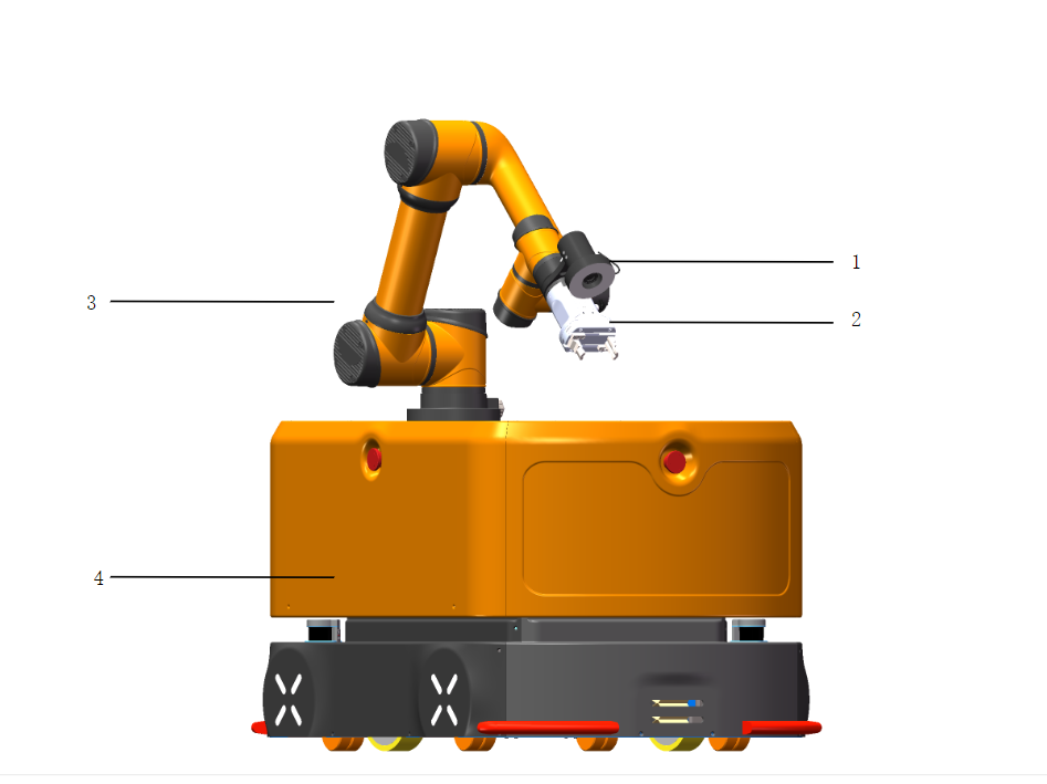
As shown in the figure above, the names of all modules are as follows:
| No. | Name |
|---|---|
| 1 | Visual camera |
| 2 | Gripper |
| 3 | AUBO collaborative robot |
| 4 | AUBO AMR 300 S |
The AUBO Haina series mobile collaborative robot can flexibly control tools such as the collaborative robot, automated guided vehicle (AGV), vision system, and end gripper. The all-in-one control system provides a simple, convenient, safe, reliable, flexibly expandable, and efficient collaborative full-scenario interactive experience. It can flexibly adapt to various working environments, eliminating complicated operations. It achieves object sorting and transportation in a mobile space through hand-eye-foot coordination. It can be used for workpiece grasping, assembly, handling, loading, and unloading, and can also be quickly deployed in automated factories, warehouse sorting, automated supermarkets, and many other scenarios, providing automated and flexible operational support for automated material handling and sorting.
3.2 Automated guided vehicle (AGV)
3.2.1 Basic functions
The automated guided vehicle (AGV) mainly has the following functions:
- Simultaneous localization and mapping (SLAM)
- Station creation and path planning
- Path navigation
- Automatic docking for charging
- Safety emergency stop and safety deceleration
- A variety of function buttons and components
- Mechanical, hardware, and software interfaces for development
3.2.2 Buttons and components
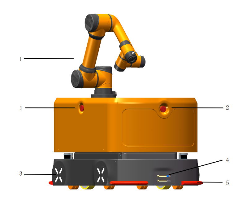

| No. | Button/Component | Description |
|---|---|---|
| 1 | AUBO collaborative robot | AUBO six-axis collaborative robot arm |
| 2 | Emergency Stop button | Press to achieve an emergency stop of the robot. To restore to normal mode, rotate this button in the direction shown on it |
| 3 | Ambient light | Indicates the robot's current status and battery level |
| 4 | Automatic charging port | Port for connecting to the automatic charger |
| 5 | Anti-collision safety edge | Used for AGV collision protection |
| 6 | Teach pendant laptop | Used to control and operate the robot |
| 7 | Compartment door keyhole | Used to open the AGV compartment door |
| 8 | Manual charging port | Port for connecting to the manual charger |
| 9 | Battery holder keyhole | Used to release or lock the battery holder latch |
| 10 | Power button | Press and hold this button to turn the AGV on or off |
| 11 | Brake release switch | Rotate the brake release switch clockwise to push the AGV manually |
| 12 | Battery holder handle | Used for battery replacement |
3.2.3 Status descriptions of power button lights
| Indicator lamp status | Robot status | Remarks |
|---|---|---|
| Solid green | Robot is powered on and standby, and motor is not powered on | After pressing and holding the power button for 3s, the green light turns on |
| Flashing green | Robot is powered on and standby, motor is not powered on, and brake release knob is in ON position | |
| Solid blue | Robot is powered on, and motor is powered on | |
| Flashing blue | Robot is powered on, motor is powered on, and brake release knob is in ON position | |
| Solid red | Only the Emergency Stop button is pressed | |
| Flashing red | Brake release mode is enabled | the brake release knob is ON, and at least one Emergency Stop button is pressed |
3.2.4 Status descriptions of ambient lights
| Light status | Equipment status | Remarks |
|---|---|---|
| Rainbow gradient | Powering on/Battery communication not established | |
| Solid green | Robot is powered on and standby, and motor is powered on | |
| Flashing green | Robot is powered on and standby, motor is not powered on, and brake release knob is in ON position | |
| Solid blue | Motor is powered on | |
| Flashing blue | Robot is powered on, motor is powered on, and brake release knob is in ON position, but emergency stop button is not triggered | |
| Breathing blue | Executing a task | |
| Solid red | Only the Emergency Stop button is pressed | |
| Flashing red | Brake release mode is enabled The indicator lamp is flashing red | The indicator light flashes red. |
| Flashing pink | Brake release knob is OFF, and Emergency Stop button is pressed The indicator lamp is solid red | The indicator light flashes pink. |
| Solid yellow | Battery level is below 50% and above 30% | |
| Breathing red | Battery level is below 30% | |
| Breathing orange | Charging | |
| Breathing red | Motor error | |
| Breathing pink | Equipment is stopped by an obstacle |
3.2.5 Technical parameters
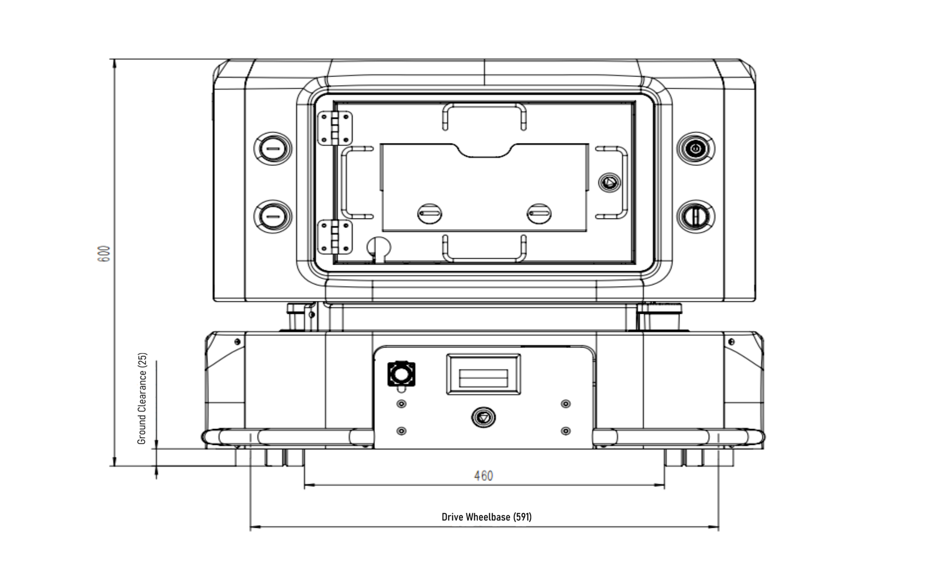
Rear view of AGV:
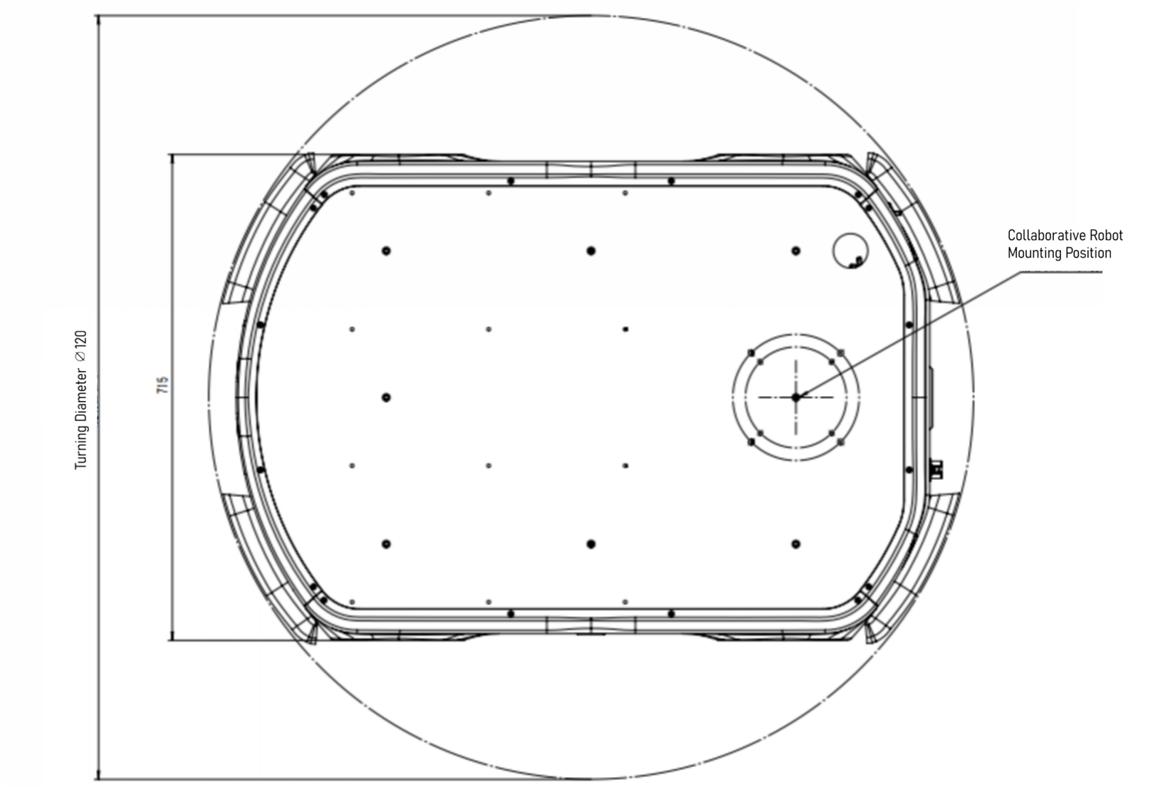
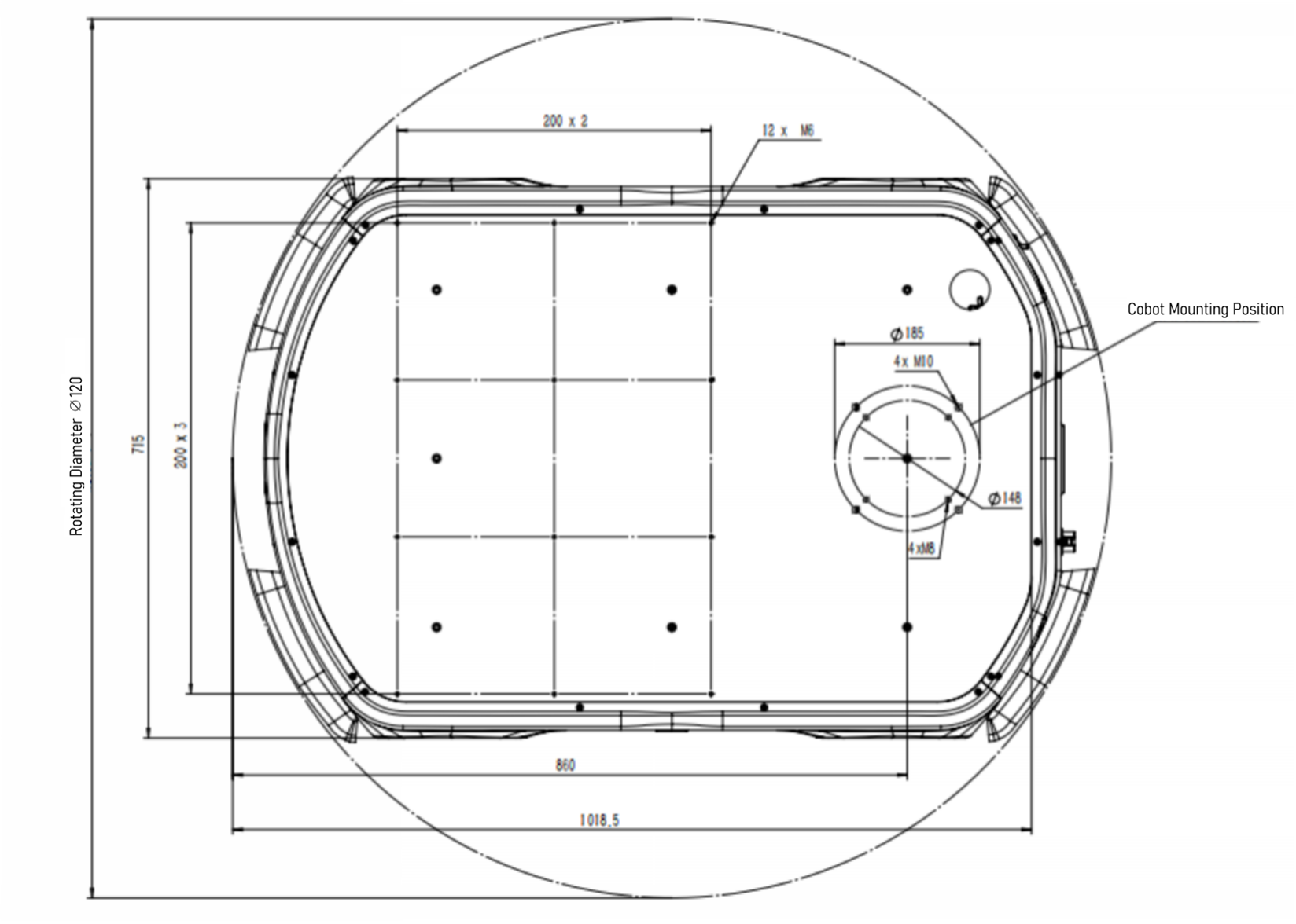
Top view of AGV:
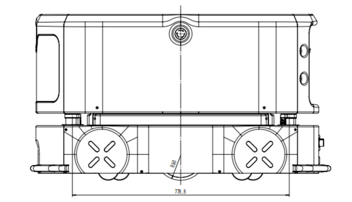
Side view of AGV:
| Category | Parameter details |
|---|---|
| Basic parameters | |
| Product model | AUBO-AMR300S |
| Dimensions (L×W×H) | 1100×715×600 mm (excluding robot arm height), tolerance: ±2 mm |
| Load surface dimensions (L×W) | 650×620 mm, tolerance: ±2 mm |
| Dead weight | 250 kg (excluding robot arm) |
| Maximum payload | 300 kg (including robot arm and carrier weight) |
| Drive type | Two-wheel differential drive |
| Motion parameters | |
| Maximum speed | 1.3 m/s |
| Operating speed | Forward: 1.0 m/s (configurable), backward: 1.0 m/s (configurable) |
| Turning radius | 0 mm |
| Rotation radius | 550 mm |
| Gradeability | 6° |
| Obstacle clearance height | 10 mm |
| Gap crossing width | 30 mm |
| Ground clearance | 25 mm |
| Travel aisle width | ≥ 900 mm |
| Turning aisle width | ≥ 1300 mm |
| Station locating accuracy | ±10 mm |
| Ground flatness | 6 mm |
| Battery performance | |
| Battery capacity | 48V 40Ah, Lithium Iron Phosphate (LFP) battery |
| Charger power supply parameter | 220V, 800-1000W |
| Battery life | 6h (with 300 kg full load) |
| Battery cycle life | 800 cycles at 100% DOD, with 80% capacity retention |
| Charging method | Manual or automatic charging optional: Maximum charging current 15A |
| Charging time | 3h (from 15% to 95%) |
| Optional equipment | |
| Robot arm | Optional AUBO-i5H, AUBO-10H, AUBO-12H, and AUBO-16H. |
| 2D camera | Adaptable to industrial 2D cameras. It adopts an eye-in-hand form, enabling 2.5D positioning with a locating accuracy of up to 0.5 mm. |
| Gripper | Adaptable to electric grippers, supporting fast loading and unloading of materials such as boxes, plates, and precision components. |
| Dual-point stable control architecture | Adopts a dual-point support structure to ensure stability in precision assembly scenarios and high-speed handling of heavy loads. |
3.3 Interfaces
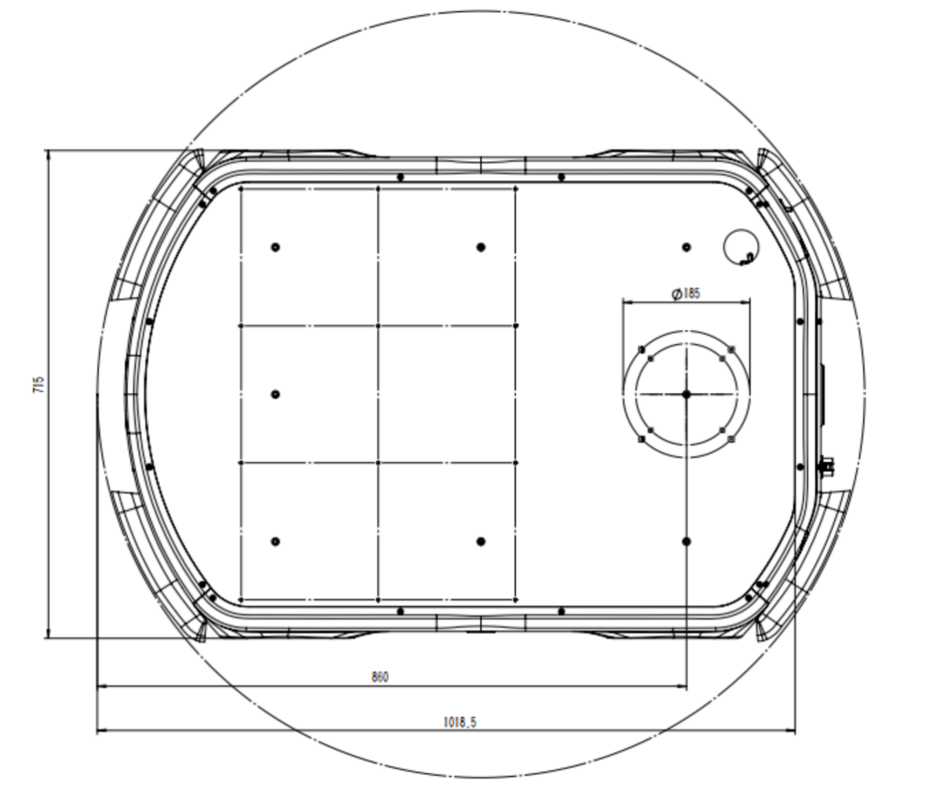
3.3.1 Mechanical interface
The mechanical interface of the mobile collaborative robot refers to the interface reserved for users, including bolt holes, locating pin holes, etc., which are used as interfaces for equipment installation in the user's application development. The mechanical interface of the AGV is located on the top surface of the AGV, as shown in the figure below.

Plannable bin area
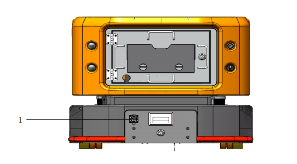
3.3.2 Electrical interface
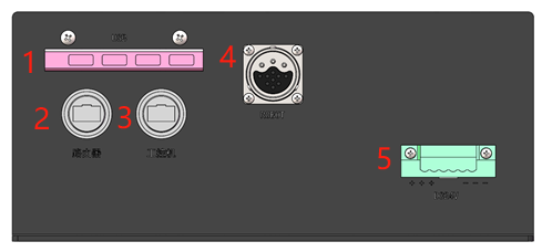
| No. | Button/Component | Description |
|---|---|---|
| 1 | USB 3.0 HUB | Led out from the USB 3.0 port of the AGV's internal IPC, used for USB devices such as USB flash drives, mice, and keyboards, and is compatible with USB 2.0. |
| 2 | Router network port | Led out from the LAN3 port of the AGV's internal router, communication rate: 100Mb/ms. |
| 3 | IPC external network port | Led out from the RJ45-3 port of the AGV's internal IPC, communication rate: 1000 Mb/s, this is a dedicated network port for the visual camera. |
| 4 | ROBOT aviation connector port | The aviation connector port for the collaborative robot cable, used for 48V power supply and communication of the collaborative robot. |
| 5 | DC24V external power supply interface | Provides external regulated 24V DC power for the visual camera and customer-selected optional equipment, with a total power of 100W. |
3.4 AUBO collaborative robot
The mobile collaborative robot uses the AUBO collaborative robot, which is characterized by its light weight, high payload-to-weight ratio, safety, and high repeated locating accuracy. It can perform high-precision assembly and installation tasks, and is suitable for tasks such as loading and unloading CNC lathes and equipment installation in industrial scenarios.
The mobile collaborative robot is adaptable to a variety of collaborative robot models, typically including: AUBO-i5H (payload 5kg) and AUBO-i10H (payload 10kg).
3.5 Optional equipment
The end effector is the device of the robot that directly comes into contact with materials, fixtures, and equipment. Typical end effectors include electric grippers, pneumatic grippers, electric suction cups, and pneumatic suction cups. Electric grippers are used more frequently on mobile collaborative robots because they do not require an air source, such as an air compressor, making them convenient to use and easy to debug.
In industrial scenarios, typical end effector tasks include gripping, sucking, and placing materials or fixtures. Materials include raw materials and finished materials, and fixtures refer to equipment used to secure materials.
A visual camera is a device for object recognition and positioning from the environment. Its components include a visual camera, a light source, a vision IPC, etc. It can be divided into 2D visual camera, 2.5D visual camera, and 3D visual camera according to the imaging and positioning principles. The visual camera is generally installed at the end of the robot arm, forming an "eye-in-hand" structure with the robot arm, and works together with devices such as electric grippers, forming the robot arm end component.
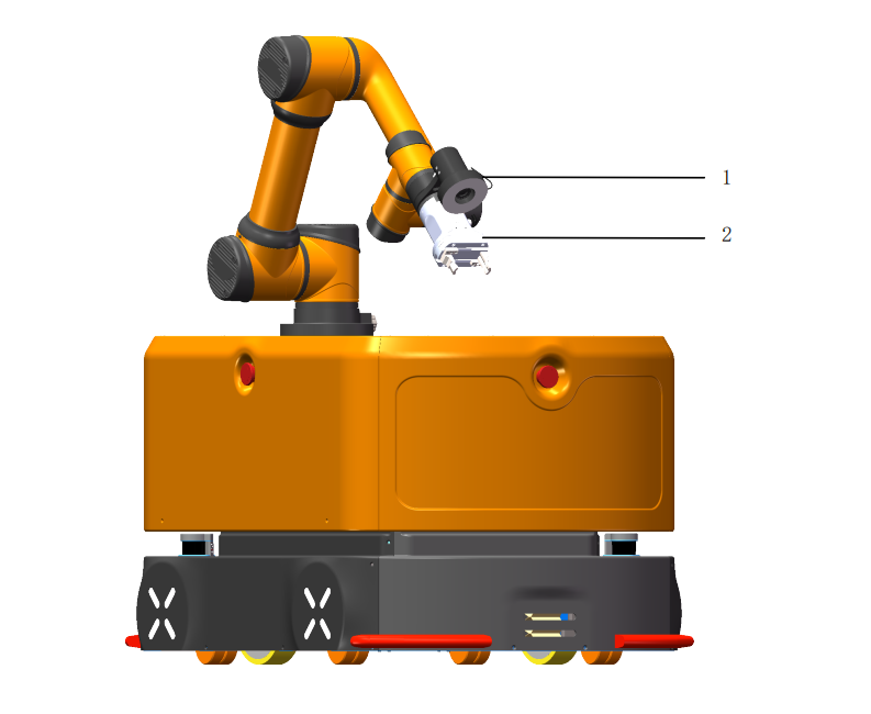
| No. | Name |
|---|---|
| 1 | Visual camera |
| 2 | Gripper |
3.6 Shipping list
The shipping list of the product is as follows (for reference only, if there are any discrepancies, please refer to the actual product):
| No. | Product | Quantity | Remarks |
|---|---|---|---|
| 1 | AUBO collaborative robot | 1 | Carton packaging |
| 2 | Composite robot chassis (AMR-300S) | 1 | Wooden case packaging |
| 3 | Robot arm connecting cable | 1 | |
| 4 | Battery manual charger | 1 | |
| 5 | Automatic charging pile | 1 | Optional |
| 6 | Laptop | 1 | Optional |
| 7 | Gripper | 1 | Optional |
| 8 | Visual camera | 1 | Optional |
| 9 | Accompanying documents | / |
4 Use of the mobile collaborative robot
4.1 Important safety instructions
4.1.1 Working environment requirements
- No corrosive gases or liquids, no oil mist, no salt spray, no dust or metal powder.
- No mechanical shock/vibration, no electromagnetic noise, no radioactive materials, low humidity, and no flammable materials.
- Ambient temperature: 0°C ~ 50°C; Relative humidity: 90% RH (non-condensing); atmospheric pressure: 86kPa ~ 106kPa。
4.1.2 Ground requirements
| Parameter Name | Parameter Value |
|---|---|
| Obstacle clearance height (the maximum height of an obstacle that the mobile collaborative robot can cross) | 10mm |
| Ground flatness (the degree of ground undulation) | 6mm |
| Gradeability (the degree of ground slope) | 6° |
| Gap crossing width (the maximum width of a gap that the mobile collaborative robot can travel over) | 30mm |
| Ground clearance (the ground clearance of the mobile collaborative robot) | 25mm |
| Warning | Precautions |
|---|---|
| 1. The ground must be flat, without grooves, damage, hollows, or contaminants such as oil or glue. 2. The ground must be free of foreign objects that can easily get stuck in or tangled with the wheels, such as screws, rags, gloves, threads, and cables. 3. The sections of the working area shall be protected or marked with warning signs to remind other personnel of the robot's presence. |
4.1.3 Travel aisle requirements
| Parameter Name | Parameter Value |
|---|---|
| Turning radius (the mobile collaborative robot uses dual-wheel differential drive and can adjust its direction in place) | 0mm |
| Rotation radius (the in-place rotation range of the mobile collaborative robot, determined by its length) | 550mm |
| Travel aisle width (the aisle width when the mobile collaborative robot travels in a straight line) | ≥900mm |
| Turning aisle width (the aisle width for the mobile collaborative robot to turn while traveling) | ≥1300mm |
4.2 Installation of robot
Take the AGV and the collaborative robot out of the packing box. The mounting hole dimensions of the AUBO-i5H collaborative robot base are shown in the figure below. Use 4 M8 bolts to fix the AUBO-i5H collaborative robot to the top surface of the AGV. The robot arm mounting point shown in the mechanical interface diagram is the installation position for the collaborative robot. During installation, ensure that the aviation connector port of the collaborative robot faces the cable hole to prevent the cable from interfering with the robot's movement. After the collaborative robot is installed, insert one end of the robot arm connecting cable into the aviation connector port of the collaborative robot base and the other end into the ROBOT aviation connector port shown in the electrical interface diagram.
少图
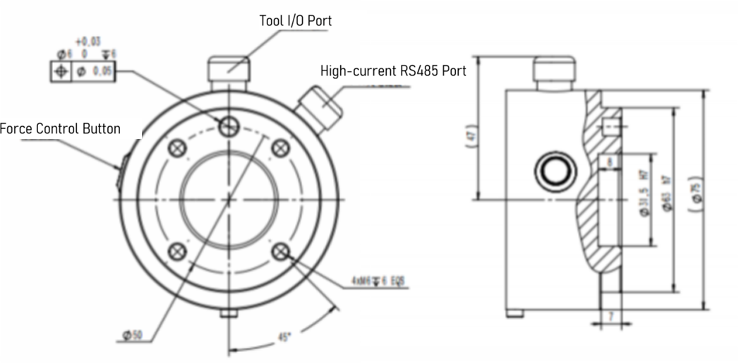
4.3 Installation of end effector
The end of the tool flange of the AUBO-i5H/i10H collaborative robot has 4 M6 threaded holes and 1 Ф6mm positioning hole, which allow for easy installation and connection of the end effector to the end of the robot. The mechanical dimensions of the tool flange are shown in the figure below.
| Warning | Precautions |
|---|---|
| 1. Ensure that the tool is correctly and securely installed. 2. Ensure the tool's safety structure is correct to prevent any parts from accidentally falling and causing danger. 3. If additional components, such as cables, that are not part of the scope of supply from AUBO (Beijing) Robotics Technology Co., Ltd. are integrated into the robot, the user is responsible for ensuring that these components have no adverse effects and do not compromise the safety features. 4. A safety assessment must be conducted after each robot installation, and safety instructions must be strictly followed. |
4.4 Power-on/off of robot
4.4.1 Powering on
Steps to power on the equipment:
- The lithium battery switch is in the ON position;
- Press and hold the Power button with light until the indicator lamp turns green, then release it (Note: Release the button quickly after the indicator lamp turns green, otherwise the equipment will initiate the shutdown procedure);
- The equipment will start the power-on procedure. When the indicator lamp turns blue, the equipment has finished powering on, and the motors are powered.
4.4.2 Powering off
Steps to power off the equipment:
- Press the switch on the side case of the lithium battery;
- Press and hold the Power button with light until the indicator lamp flashes green, and then release it. The equipment will initiate the shutdown procedure;
- When the button indicator lamp goes off, the equipment shutdown is complete;
- If the equipment will not be used for a long time after shutdown, the metal button switch on the side of the battery must also be turned off (in the popped-out state), otherwise it may easily cause over-discharge of the lithium battery. If the lithium battery level is already low at shutdown, it is recommended to fully charge the lithium battery before turning off the side metal button. It is required to perform a charge-discharge cycle for the battery pack every 28 days.
4.4.3 Emergency stop
Red Emergency Stop buttons are installed on the front, left, and right shells of the composite robot's mobile chassis. To stop the equipment in an emergency, press any of these three buttons to bring the composite robot to an emergency stop.
After the equipment fault is cleared, rotate the Emergency Stop button clockwise to complete the reset and release the equipment from the emergency stop state.
4.4.4 Brake release
The brake release for the composite robot includes brake release in the powered-off state and brake release in the powered-on state.
After the brake release, the brakes of the drive motors are disengaged, and the AGV can be pushed by a single person.
Brake release in the powered-off state: The following three conditions must be met:
- The lithium battery switch is in the ON position;
- Turn the brake release knob to the right;
- Press at least one Emergency Stop button;
Brake release in the powered-on state: The following three conditions must be met:
- The AGV is in the powered-on state;
- Turn the brake release knob to the right;
- Press at least one Emergency Stop button;
As can be seen, to release the brake of the AGV, be sure to press at least one Emergency Stop button and simultaneously turn the brake release knob to the right.
4.5 Charging of robot
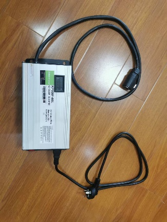
The composite robot's lithium battery charging is divided into two modes: automatic charging and manual charging. The automatic charging mode needs a charging pile (the charger is installed inside the charging pile housing), while the manual charging mode needs a charger.
Charger model: KP900F-60L-1h
Refer to the table below for the technical parameters of the automatic charging pile/charger:
| No. | Product | Remarks |
|---|---|---|
| 1 | Maximum output voltage | 54.6V+0.2V |
| 2 | Output current | 15A+5% |
| 3 | Maximum output power | 900W |
| 4 | Input voltage | 180-260Vac |
| 5 | Rated input voltage | 220Vac |
| 6 | Rated output | 15A |
| 7 | Input frequency | 50-60Hz |
| 8 | Conversion current | 0.75A |
Environmental condition requirements:
| No. | Parameter type | Technical parameter |
|---|---|---|
| 1 | Operating temperature | -20-45°C |
| 2 | Relative humidity | 5%-95% |
| 3 | Storage temperature | -40-70°C. |
| 4 | Cooling method | Forced air cooling |
| 5 | Altitude | 0-3000m |
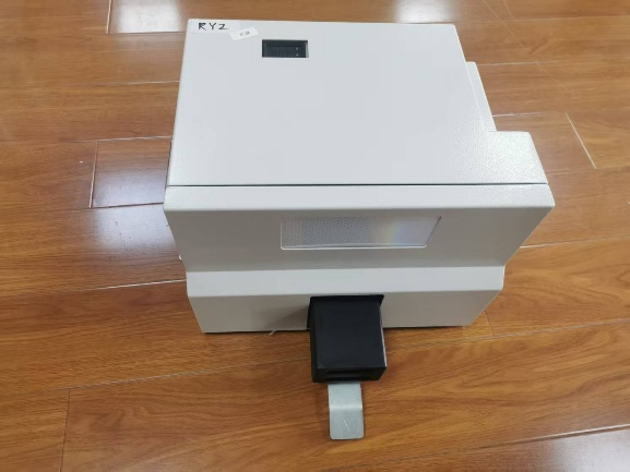
The actual charging pile and charger are shown in the figure below: Charging pile:
Charger:
4.5.1 Automatic charging
The composite robot/mobile chassis AGV is controlled by the upper-level software or scheduling system to automatically drive to the charging pile for charging.
4.5.2 Manual charging
The composite robot/mobile chassis AGV is manually charged by an operator using a charger.
The location of the manual charging port is shown in the figure:
When charging, ensure that the plug and socket are fully and tightly connected. Poor connections are strictly prohibited to avoid serious consequences such as sparking, melting of the port, or even equipment damage.

When performing manual charging, ensure that the charger plug and the charging port socket are fully connected to prevent dangers and losses caused by poor connections.
| Warning | Safety regulations for charging |
|---|---|
| 1. Please use the original charger. Do not use chargers from other brands, as this may cause irreversible damage to the battery. 2. The battery poses risks of fire, explosion, etc. Do not disassemble, crush, incinerate, heat, or throw the battery into a fire. 3. Do not immerse the battery in water or get it wet. 4. Do not allow the positive and negative terminals of the battery to come into contact with the metal casing at the same time. 5. Do not short-circuit, overcharge, or over-discharge the battery. 6. Do not use or store the battery near heat sources (such as fire and heaters). 7. Do not reverse the positive and negative terminals of the battery. | 8. Do not pierce the battery casing with nails or other sharp objects. Do not hammer or step on the battery. 9. Do not disassemble or modify the battery in any way without authorization. 10. Do not hit, throw, or subject the battery to mechanical vibrations or drops. 11. Do not mix batteries of different types or brands. 12. If the battery emits an unusual odor, becomes hot, deforms, changes color, or exhibits any other abnormal phenomena, stop using it and move it away from the operating environment. 13. If the battery catches fire, use a dry powder or foam fire extinguisher, sand, etc., to extinguish the fire and move the battery away from the operating environment. |
4.6 Optional equipment
4.6.1 Vision module
Electrical wiring
For the hardware installation, refer to the IO trigger camera light source wiring and configuration method of the Hikvision industrial camera.
The camera pin numbers are as follows:

The camera pin functions are as follows:
| Pin | Signal | I/O Signal Source | Description | Cable Color |
|---|---|---|---|---|
| 1 | DC\PWR | - | Camera power supply | Orange |
| 2 | OPTO\IN | Line 0+ | Optocoupler isolated input | Yellow |
| 3 | GPIO | Line 2 | Configurable input or output | Purple |
| 4 | OPTO\OUT | Line 1+ | Optocoupler isolated output | Blue |
| 5 | OPTO\GND | Line 0/1- | Optocoupler isolated signal ground | Green |
| 6 | GND | Line 2- | Camera power ground | Gray |
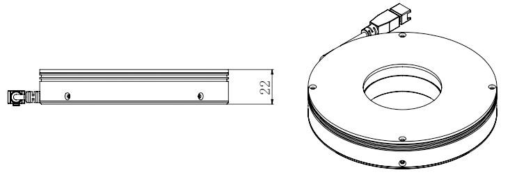
The appearance of the light source is shown in the figure below:
Electrical wiring of AUBO AMR300 composite robot vision module:
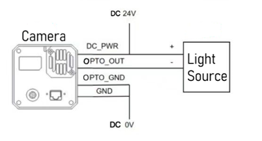
- Connect the camera power DC\PWR (orange) and the positive terminal of the light source (usually blue, but may vary with the light source batch) to DC24V;
- Connect the camera power ground GND (gray) and the optocoupler isolated signal ground OPTO\GND (green) to DC0V;
- Connect the optocoupler isolated output OPTO\OUT (blue) to the light source power ground (usually black, but may vary with the light source batch);
- Connect the input and output ends of the network cable to the robot network port and the camera communication network port respectively.
The vision module shall be wired when the power is off. After checking that everything is correct, you can turn on the power for testing.
4.6.2 Electric gripper
Model: Junduo RD75-300, Power supply: DC24V; Communication: RS485。
Electrical wiring:
The gripper is installed at the end of the iH series robot arm and supports two wiring methods:
- Connect the gripper cable to the P6 interface at the end of the robot arm to achieve 24V power supply and 485 communication;
- Connect the gripper cable to the robot's 2.3.2 electrical interface, draw power from the DC24V external power supply interface, and connect the 485 communication signal to the USBHUB interface via a USB converter.
5 Transportation and storage
5.1 Transportation
The robot can only be transported in its original packaging. If you need to move the robot in the future, please keep the packaging materials in a dry place. During packaging for transportation, the robot shall be packed according to the packaging standards, and the required marks shall be placed on the outside of the packing box. For hoisting the robot, appropriate measures shall be taken to position the moving components to prevent them from causing hazards due to unexpected movements during hoisting and transportation. During transportation, ensure that the robot is stable and fixed in a proper position.
| Warning Sign | Transportation Requirements |
|---|---|
| 1. During transportation, the AGV needs to be packed with wooden boxes and foam, which are already provided with the product. 2. The robot's brakes need to be locked during transportation to prevent battery loss. Failure to do so will lead to battery consumption and risk of battery damage. 3. Ensure that your back or other body parts are not overstrained when lifting the equipment. 4. All regional and national guidelines shall be followed. AUBO (Beijing) Robotics Technology Co., Ltd. is not responsible for any damage caused during equipment transportation. 5. Keep the original packaging intact after transportation is complete. Store the packaging materials in a dry place in case you need to repack and move the robot in the future. |
5.2 Storage
5.2.1 Storage of robot
For robots that are out of service for a long time, take anti-corrosion measures during storage, disconnect the battery from the robot (turn off the battery switch), and ensure that the battery is recharged once a month.
5.2.2 Storage of battery
- The battery pack shall be stored at an ambient temperature of 0-40°C and a relative humidity of 10%-90% RH;
- Avoid contact with corrosive substances or magnetic environments;
- The battery pack shall be stored in a clean, dry, and ventilated environment, away from fire or heat sources;
- When storing the battery for a long time without use, turn off the battery switch and fully charge the battery pack once a month.
5.2.3 Storage of charger
- It shall be placed in the packaging box when not in use;
- Storage temperature: -40°C to 70°C, relative humidity: 5% to 95%, and the warehouse must be free of harmful gases, flammable materials, explosives, corrosive chemicals, strong mechanical vibrations, shocks, and magnetic field effects;
- The packaging box shall be placed at least 20 cm above the ground and 50 cm away from walls, heat sources, and vents;
- It can be stored for two years under these storage conditions, and must be re-inspected if it exceeds two years;
- It must be powered on once every three months for not less than 0.5 hours.
6 Maintenance and disposal of product
6.1 Maintenance of product
Maintenance and repair work must strictly comply with all safety instructions in this manual. Repairs must be performed by an authorized system integrator or AUBO (Beijing) Robotics Technology Co., Ltd. Parts returned to AUBO (Beijing) Robotics Technology Co., Ltd. shall be handled in accordance with the provisions of the service manual.
It is necessary to ensure the safety level specified for maintenance and repair work, comply with effective national or regional work safety regulations, and test all safety features to ensure they are functioning properly.
The purpose of maintenance and repair work is to ensure the normal operation of the system or to help restore it to a normal state in the event of a system failure. Repair includes fault diagnosis and physical repair.
Only authorized personnel who have received safety and other relevant training can maintain the robotic system. Other relevant training includes robotic system training and maintenance training conducted by the manufacturer, distributor, or local importer. Operators shall participate in safety training in accordance with national regulations. The following safety procedures and warnings must be followed during operation of the robot arm or control cabinet:
| Warning: Safety | Regulations for maintenance |
|---|---|
| 1. Please comply with ESD (Electrostatic discharge) regulations when disassembling the robot. 2. Prevent water or dust from entering the robot. 3. Replace faulty components with new components with the same part number or corresponding components approved by AUBO (Beijing) Robotics Technology Co., Ltd. 4. The company will not assume any responsibility for the unauthorized use of unapproved components. The company is not responsible for any damage to the robot, accessories, or any other equipment caused by the use of unapproved components. |
6.1.1 Replacement of battery
When the robot battery is damaged or reaches its specified service life, it can be replaced according to the following steps:
- Power off the robot and disconnect the equipment from the power supply;
- Unlock the battery holder and pull it out;
- Disconnect the manual charging cable connector and take out the battery;
- Place the new battery into the battery holder and plug in the manual charging cable connector;
- Push in the battery holder and lock the door to complete the battery replacement.
| Warning | Precautions for replacement |
|---|---|
| 1. When replacing the battery, be careful not to pinch your hands in the battery holder door. 2. After replacing the battery, please fully close and lock the battery holder door. Prevent the battery from sliding out of the vehicle body during operation. |
6.1.2 Safety contact edge
After the safety contact edge is installed, the normally closed signal cable connector needs to be plugged into the corresponding contact edge controller SEI SE2 signal connector.
6.1.3 Visual camera
The visual components (camera and light source) draw power from the 24V external power supply port on the electrical interface panel. Note that the positive and negative terminals of the equipment must correspond to the positive and negative terminals of the power supply.
6.2 Disposal
The AUBO robot must be disposed of in accordance with applicable national laws, regulations, and standards.
7 Quality assurance
7.1 Quality assurance of product
The AUBO mobile robot has a 18-month limited warranty.
If the new equipment and its components show defects due to poor manufacturing or poor materials within 36 months after being put into use, AUBO (Beijing) Robotics Technology Co., Ltd. shall provide the necessary spare components for replacement or repair the related components.
All equipment or components replaced or returned to AUBO (Beijing) Robotics Technology Co., Ltd. are owned by AUBO (Beijing) Robotics Technology Co., Ltd. If the product is no longer within the warranty period, AUBO (Beijing) Robotics Technology Co., Ltd. reserves the right to charge the customer for replacement or repair fees.
Outside the warranty period, if the equipment exhibits defects, AUBO (Beijing) Robotics Technology Co., Ltd. shall not be liable for any resulting damage or loss, such as production loss or damage to other production equipment.
7.2 Disclaimer
The "Product Quality Warranty" becomes void if the equipment defect is caused by improper handling or failure to follow the relevant information described in the User Manual.
Failures caused by the following situations are not covered by this warranty:
- Products purchased from channels not authorized by AUBO;
- Installation, wiring, or connection to other control equipment that does not comply with industrial standards or the requirements of the User Manual;
- Use beyond the specified conditions or standards of the product;
- Using this product for purposes other than those specified;
- Operating environmental conditions that exceed the product's specifications;
- Use in a grinding environment or other special environments without proper product protection; Product damage caused by improper transportation;
- Failures, damage, or indirect damage caused by accidents or human factors;
- Failures, damage, or indirect damage caused by modifications;
- Installation of parts or accessories that are not genuine;
- Damage caused by modification, commissioning, or repair of genuine parts by a third party other than AUBO (Beijing) Robotics Technology Co., Ltd. or its designated integrators;
- Failures, damage, or indirect damage caused by natural disasters or other force majeure events;
- Failures caused by reasons other than the responsibility of AUBO (Beijing) Robotics Technology Co., Ltd., in addition to the situations mentioned above.
The following situations are not covered by the warranty:
- The product traceability number cannot be identified.
- The production date or warranty start date cannot be identified.
- Changes to software or internal data.
- The failure cannot be reproduced or identified by AUBO (Beijing) Robotics Technology Co., Ltd.
- Use of this product with radioactive equipment, in biological testing equipment, or for purposes deemed hazardous by AUBO (Beijing) Robotics Technology Co., Ltd.
- Appearance parts and wearing parts.
According to the product quality warranty agreement, AUBO (Beijing) Robotics Technology Co., Ltd. only provides warranty commitments for flaws and defects in products and parts sold to distributors.
AUBO (Beijing) Robotics Technology Co., Ltd. disclaims any other express or implied warranties or liabilities, including but not limited to any implied warranty of merchantability or fitness for a particular purpose. Furthermore, AUBO (Beijing) Robotics Technology Co., Ltd. is not liable for any form of indirect or consequential damages arising from the related products.
7.3 List of wearing parts
| No. | List of Wearing Parts |
|---|---|
| 1 | Nameplate |
| 2 | Robot arm connecting cable |
| 3 | Battery manual charger power cord |
| 4 | AGV door panel key |
Appendix I: Fault Descriptions and Solutions
| Symptom | Fault Cause | Solution |
|---|---|---|
| The mobile collaborative robot cannot be charged. | The battery aviation connector cable has poor contact. | Replace the aviation connector cable or aviation connector. |
| The manual charger is damaged. | Replace the manual charger. | |
| The 24V power module is damaged. | Replace the power module. | |
| After the Emergency Stop button is pressed, the mobile collaborative robot sways back and forth, and the rear tends to lift off the ground. | The equipment on the AGV's upper platform is unevenly distributed. | Increase the load on the rear of the AGV. |
Appendix II: Parameter Information
| Category | Parameter details |
|---|---|
| Product model | AUBO-AMR300S |
| Dimensions (L×W×H) | 1,000×700×600 mm (excluding robot arm height), tolerance: ±2 mm |
| Load surface dimensions (L×W) | 650×620 mm, tolerance: ±2 mm |
| Dead weight | 250 kg (excluding robot arm) |
| Maximum payload | 300 kg (including robot arm and carrier weight) |
| Drive type | Two-wheel differential drive |
| Number of laser sensors | 2 |
| Motion parameters | |
| Maximum speed | 1.3 m/s |
| Operating speed | Forward: 1.0 m/s (configurable), backward: 1.0 m/s (configurable) |
| Turning radius | 0 mm |
| Rotation radius | 550 mm |
| Gradeability | 6° |
| Obstacle clearance height | 10 mm |
| Gap crossing width | 30 mm |
| Ground clearance | 25 mm |
| Travel aisle width | ≥ 900 mm |
| Turning aisle width | ≥ 1300 mm |
| Station locating accuracy | ±10 mm |
| Ground flatness | 6 mm |
| Battery performance | |
| Battery capacity | 48V 40Ah, Lithium Iron Phosphate (LFP) battery |
| Charger power supply parameter | 220V, 800-1000W |
| Battery life | 6h (with 300 kg full load) |
| Battery cycle life | 800 cycles at 100% DOD, with 80% capacity retention |
| Charging method | Manual or automatic charging optional: Maximum charging current 15A |
| Charging time | 3h (from 15% to 95%) |
| Optional equipment | |
| Robot arm | Optional AUBO-i5H, AUBO-10H, AUBO-12H, and AUBO-16H. |
| 2D camera | Adaptable to industrial 2D cameras. It adopts an eye-in-hand form, enabling 2.5D positioning with a locating accuracy of up to 0.5 mm. |
| Gripper | Adaptable to electric grippers, supporting fast loading and unloading of materials such as boxes, plates, and precision components. |
| Dual-point stable control architecture | Adopts a dual-point support structure to ensure stability in precision assembly scenarios and high-speed handling of heavy loads. |