User Manual for AUBO Haina Series Composite Robot
1 Copyright and disclaimer
Version information
v1.0.0
The User Manual will be subject to regular check and revision, and updated content will appear in new versions. The content or information in this manual is subject to change without prior notice. AUBO (Beijing) Robotics Technology Co., Ltd. is not responsible for any errors or omissions that may appear in this manual, or for any accidental or indirect damages resulting from the use of this manual and the products described herein. Please read this manual before installing and using the product. Please keep this manual properly for reading and reference at any time. All figures in this manual are for illustrative purposes only. The actual product received shall prevail. This manual is the exclusive property of AUBO (Beijing) Robotics Technology Co., Ltd. It may not be photocopied, reproduced in whole or in part, or converted into any other form without the written permission of AUBO (Beijing) Robotics Technology Co., Ltd.
Copyright © 2015-2026 AUBO All rights reserved.
2 Installation of hardware
2.1 Basic accessories
| No. | Accessory Name | Image |
|---|---|---|
| 1 | AUBO collaborative robot arm | 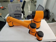 |
| 2 | Mobile chassis |  |
| 3 | 2D industrial camera |  |
| 4 | Automatic charging pile | 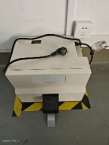 |
| 5 | Laptop |  |
| 6 | Manual charger | 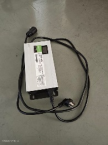 |
| 7 | Robot arm connecting cable | 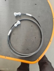 |
| 8 | Camera network cable | 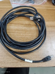 |
| 9 | Machine power cord and light source extension cable | 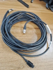 |
| 10 | Electric gripper | 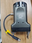 |
| 11 | Electric gripper cable | 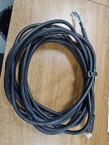 |
| 12 | Lithium battery | 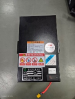 |
| 13 | USB to 485 module | 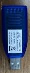 |
2.2 Introduction to buttons and interfaces
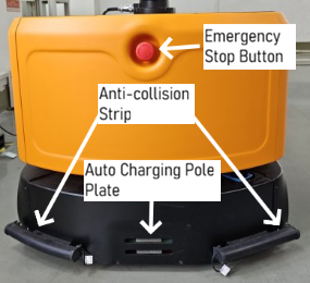
Figure 1
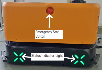
Figure 2
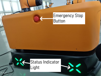
Figure 3
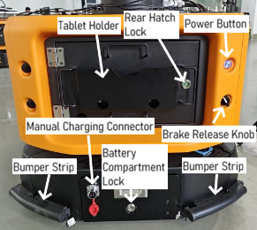
Figure 4
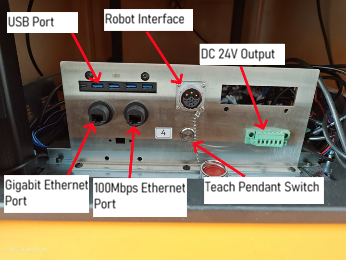
Figure 5
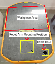
Figure 6
- Emergency Stop button: The Emergency Stop buttons are located on the front, left and right sides of the upper layer of the mobile chassis, as shown in Figure 1, Figure 2, and Figure 3. They are used for emergency stop of the equipment.
- Power button: The Power button is located at the rear of the equipment chassis, as shown in Figure 4. It is used to power the equipment on and off. Its indicator lamp shows the current status of the equipment.
- Brake Release knob: The Brake Release knob is located at the rear of the equipment chassis, as shown in Figure 4. It is used for emergency stop of the equipment.
- Bumper strip: This equipment has a total of 4 bumper strips, located at the four corners of the equipment chassis, as shown in Figure 1 and Figure 4. They are used for emergency stop after the chassis collides with an object during movement.
- Automatic charging port: The automatic charging port is located at the front of the mobile chassis, as shown in Figure 1. It is used for connection to a charging pile for automatic charging.
- Manual charging port: The manual charging port is located at the rear of the mobile chassis, as shown in Figure 4. It is used for connection to a manual charger for manual charging.
- Status indicator lamp: The status indicator lamps are located on both sides of the equipment, as shown in Figure 2 and Figure 3. They will show the current status of the equipment and the battery level.
- Laptop holder: The laptop holder is located on the rear compartment door of the equipment, as shown in Figure 4. It is used to hold a laptop computer.
- Rear compartment door lock: As shown in Figure 4, it secures the rear compartment door to prevent it from opening while the chassis is moving.
- Battery holder lock: As shown in Figure 4, it secures the battery holder to prevent it from sliding out while the chassis is moving.
- USB3.0: As shown in Figure 5.
- Robot arm aviation connector: As shown in Figure 5, it is used to connect the robot arm.
- 24V power output: As shown in Figure 5, it is used to provide 24V DC power to external equipment.
- Teach pendant switch: As shown in Figure 5, when a wired teach pendant is connected, this button must be pressed to enable the emergency stop function of the teach pendant.
- 100M Ethernet port: As shown in Figure 5, it is used for connection to a network interface.
- Gigabit Ethernet port: As shown in Figure 5, it is used for connection to a network interface.
- Equipment loading area: As shown in Figure 6, this area is used for installing material racks or placing materials carried by the vehicle.
- Robot arm mounting position: As shown in Figure 6, this position is used for installing the robot arm.
- Cable hole: As shown in Figure 6, this hole is used for passing through the cables of external equipment.
2.3 Status description of indicator lamps
| Status Category | Trigger Condition/Operation | Light Indication |
|---|---|---|
| Emergency stop status | Press the Emergency Stop button | ◉ Power indicator lamp: Solid red ◉ Chassis light: Flashing dark red |
| Power-on and standby | ||
| During power-on | Press and hold the power button until the green light turns on | ◉ Power indicator lamp: Solid green ◉ Chassis light: Rainbow gradient effect |
| Power-on complete | The system has finished starting up | ◉ Power indicator lamp: Solid blue ◉ Chassis light: Color changes with the battery level ✓ Sufficient >50%: Green ✓ Medium 30%: Orange ✓ Low battery(<30): red |
| Brake release status | Rotate the Brake Release Knob | |
| During AGV power-off | ◉ Power indicator lamp: Fast flashing red (2Hz) ◉ Chassis light: Synchronized fast flashing red | |
| During power-on | ◉ Power indicator lamp: Slow flashing green (1Hz) ◉ Chassis light: Slow flashing red | |
| Standby status | ◉ Power indicator lamp: Slow flashing blue ◉ Chassis light: Slow flashing red | |
| Task status | ||
| During navigation | Executing a path navigation task | ◉ Power indicator lamp: Solid blue ◉ Chassis light: Breathing blue effect (fading in and out) |
| During charging | Be connected to a charging pile | ◉ Power indicator lamp: Solid blue ◉ Chassis light: Breathing orange-yellow effect |
| Abnormal status | ||
| Power interruption | External power supply disconnected | ◉ Power indicator lamp: Solid blue (to be confirmed) ◉ Chassis light: Breathing pink effect |
| Fault alarm | System detects an abnormality | ◉ Chassis light: ✓ Rainbow cycle effect ✓ or rapid red flashing (3Hz) |
2.4. Installation of hardware
2.4.1 Installation of robot arm
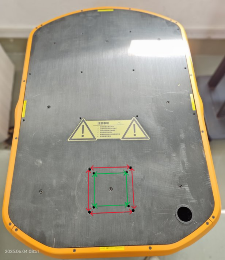
Figure 1
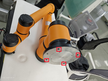
Figure 8
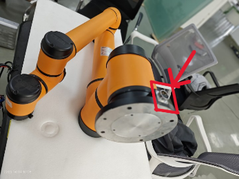
Figure 9
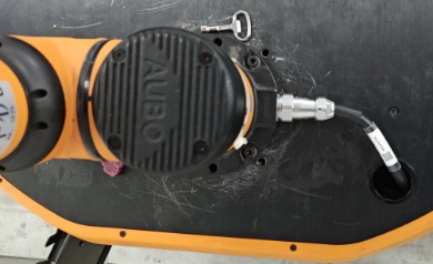
Figure 10
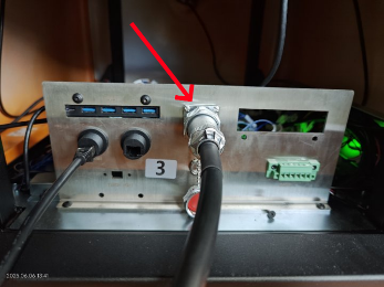
Figure 11
The red and green double-headed arrows in Figure 7 indicate the mounting holes for the robot arm on the top surface of the mobile chassis. The holes indicated by the red arrow are the mounting screw holes for the robot arms of models i10 and above. The screw holes indicated by the green arrow are the mounting screw holes for the robot arms of models i5 and i7.
Select the appropriate mounting holes according to the robot arm model and install the robot arm onto the chassis (see Figure 8 for the robot arm screw holes). Connect one end of the robot arm connecting cable to the aviation connector at the base of the robot arm (Figure 9), and pass the other end through the cable hole on the top surface of the chassis (Figure 10) for connection to the ROBOT interface aviation connector on the mobile chassis (Figure 11).
2.4.2 Installation of industrial camera
Use M6×14mm socket head cap screws (Figure 12) to install the camera module onto the robot arm flange (see Figure 13 for flange mounting holes, and Figure 14 for camera screw holes). The completed installation is shown in Figure 15.
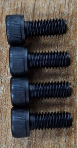
Figure 12
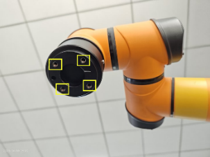
Figure 13
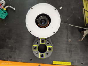
Figure 14
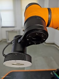
Figure 15
Using the camera network cable, insert one end into the camera's network port and tighten the crystal head fixing screw (Figure 16), then pass the other end through the cable hole on the top surface of the chassis and insert it into the Gigabit Ethernet port on the interface board (Figure 17).
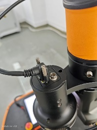
Figure 16
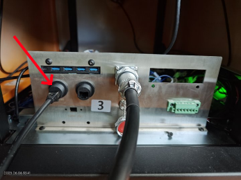
Figure 17
Using the camera power cord and the light source extension cable, connect one end to the camera's power port and the light source power cord (Figure 18, Figure 19), and pass the other end through the cable hole on the top surface of the chassis and insert it into the DC24V output interface on the interface board (Figure 20). Do not reverse the positive and negative poles.
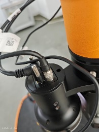
Figure 18
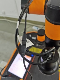
Figure 19
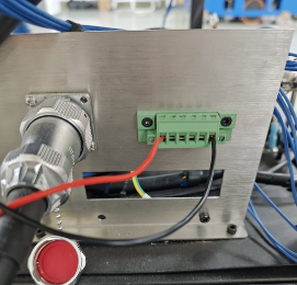
Figure 20
2.4.3 Installation of gripper
Remove the flange connecting block of the electric gripper (Figure 22);
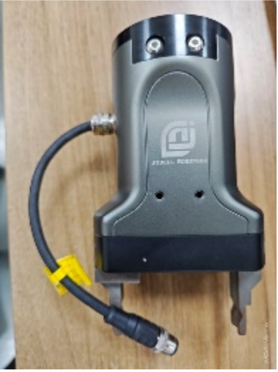
Figure 21
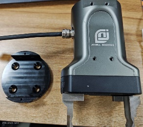
Figure 22
Use M6×14mm flat head socket screws (Figure 23) to install the gripper connector below the camera flange connector (Figure 24);
Figure 23
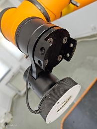
Figure 24
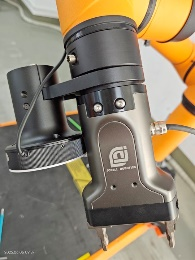
Figure 25
Install the main body of the electric gripper onto the gripper connector (Figure 25);
Insert one end of the electric gripper cable's aviation plug into the female aviation connector on the electric gripper, and rotate the fixing nut to tighten it (Figure 26); pass the other end of the cable through the cable hole on the top surface of the chassis. Insert the brown wire (positive pole) into the positive terminal of the DC24V output on the interface board, insert the blue wire (negative pole) into the positive terminal of the DC24V output on the interface board, connect the white wire (485A interface) to the A interface of the USB to 485 module, connect the black wire (485B interface) to the B interface of the USB to 485 module (Figure 27), and plug the USB male connector of the USB to 485 module into the USB port on the interface panel (Figure 28).
Figure 26
Figure 27
Figure 28
The electric gripper installation is complete.
3 Basic operation
3.1 Replacement of battery
- Shut down the equipment
- Unlock and pull out the battery holder
- Unplug the battery connector and take out the original battery
- Put in the new battery and plug in the battery connector
- Push in and lock the battery holder
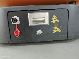
Figure 29
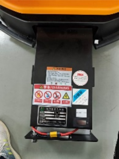
Figure 30
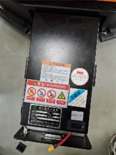
Figure 31
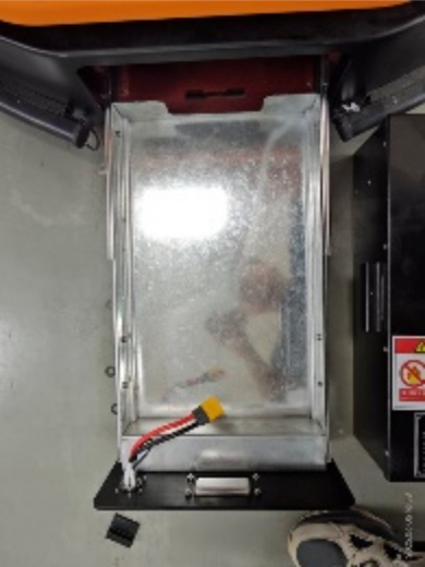
Figure 32
3.2 Brake release of equipment
When you need to manually push and move the equipment, first ensure that the equipment's battery has power before releasing the brake.
The steps for brake release are as follows:
- Turn the brake release knob to the right。
- Press the Emergency Stop button。
- Move the equipment。
- Turn the brake release knob to the left。
- Pull out the Emergency Stop button。
Note:
Unless absolutely necessary, do not keep the brake release knob in the right-turned position for an extended period!! After the equipment is shut down, turning the brake release knob to the right will cause the battery to continuously discharge, which can easily deplete and damage the battery.
3.3 Power-on/off of the equipment
- Power-on: When the equipment is off, press and hold the Power button until its indicator lamp turns solid blue;
- Power-off: When the equipment is on, press and hold the Power button until its indicator lamp flashes green.
3.4 Manual charging
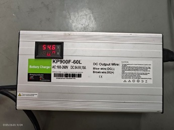
Figure 33
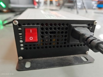
Figure 34
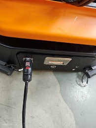
Figure 35
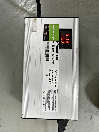
Figure 36
Insert the three-prong plug of the manual charger into a 220V three-hole socket. Wait until the manual charger's display shows a voltage of around 54.6V (Figure 33). Then, plug the charger's aviation connector into the equipment's manual charging aviation connector port (Figure 35). When the charger's display shows a current other than 0 (Figure 36), the manual charging operation is complete, and the equipment begins to charge normally.
3.5 24V power supply wiring for external equipment
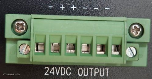
Figure 37
The equipment's 24V power supply interface is located on the equipment's interface panel, as shown in Figure 16. The specific interface is indicated by arrow 3 in the figure, as shown in Figure 37. Connect the positive terminal of the external equipment's power supply to the positive terminal on the left side of this interface, and connect the negative terminal of the external equipment's power supply to the negative terminal on the right side of this interface.
4 Software installation and update
4.1 Installation of Steering client
Download address of Steering client: https://download.aubo-robotics.cn/pre-release/amr/

Select the installation package named "Steering" and double-click to download it.
Import this installation package into the laptop, or download it using the laptop's browser.
Follow the Android software installation guide to proceed.
4.2 ARCS client update
Download address of ARCS client: https://download.aubo-robotics.cn/pre-release/android/
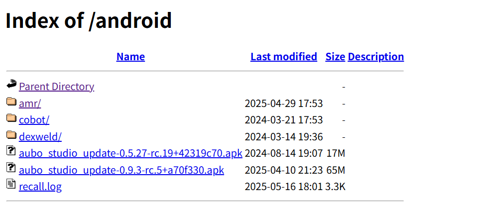
Select the installation package named "aubostudioupdate" and double-click to download it.
Import this installation package into the laptop, or download it using the laptop's browser.
Follow the Android software installation guide to proceed.
4.3 ARCS update
Go to the aubostudio page and click "Settings > System > Update" to display the following list.
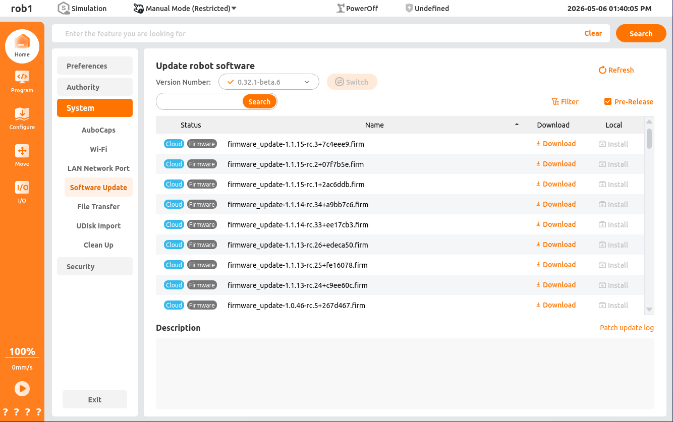
Select the version you want to update and click to download it.
Follow the guide to complete the installation.
5 Network configuration
5.1 Industrial gateway configuration of robot
Connect the laptop to the router and enter the URL 192.168.168.200 to access the router's web page.
Enter the account name admin and the password Admin-985#.
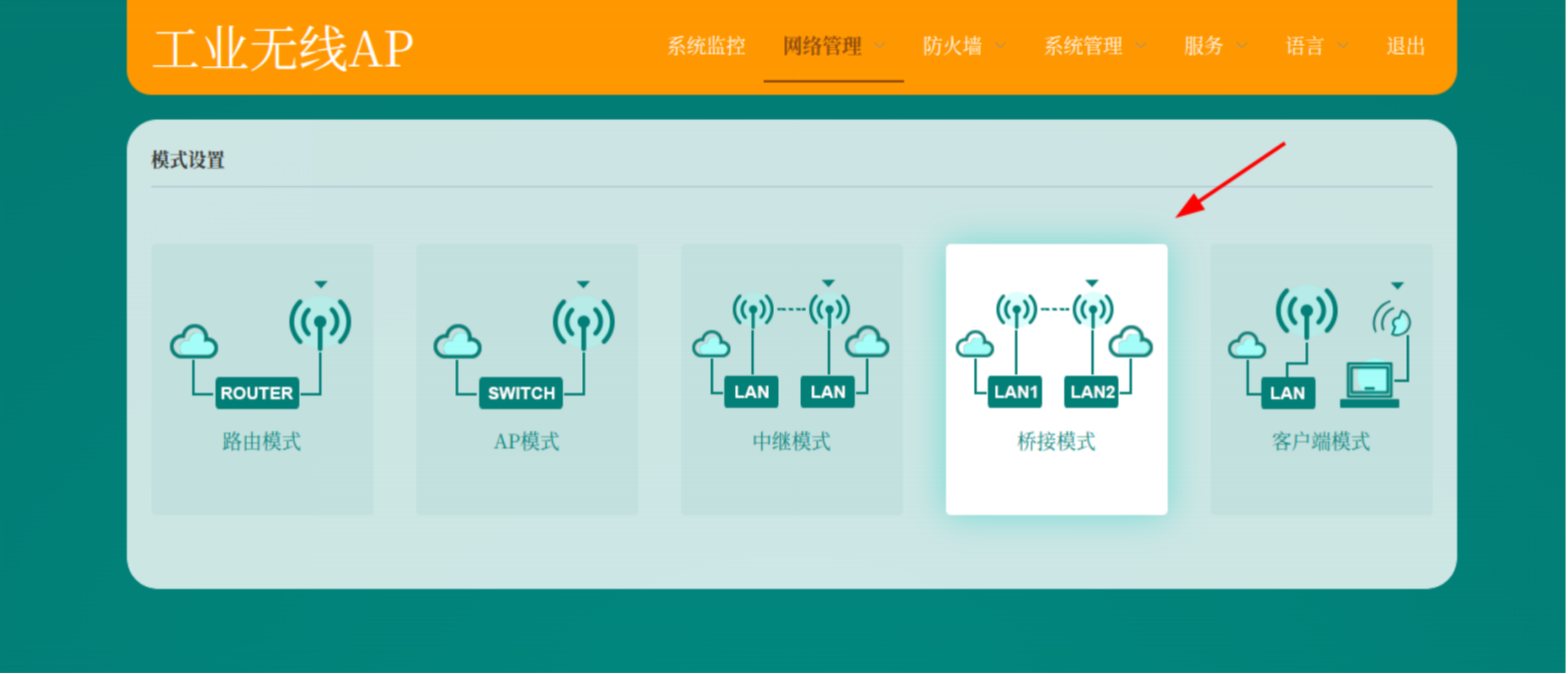
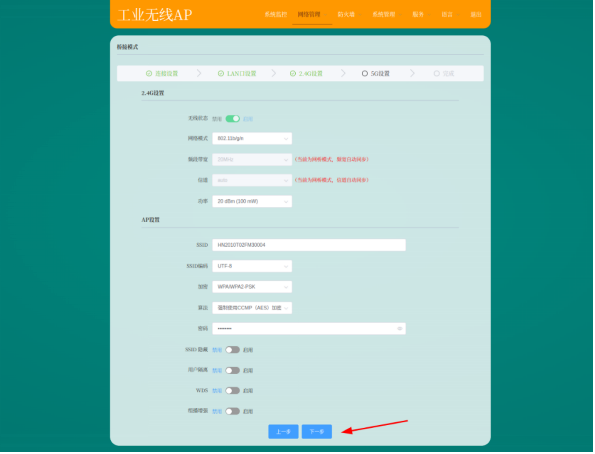
Enter "Network Management" and select "Bridge Mode".
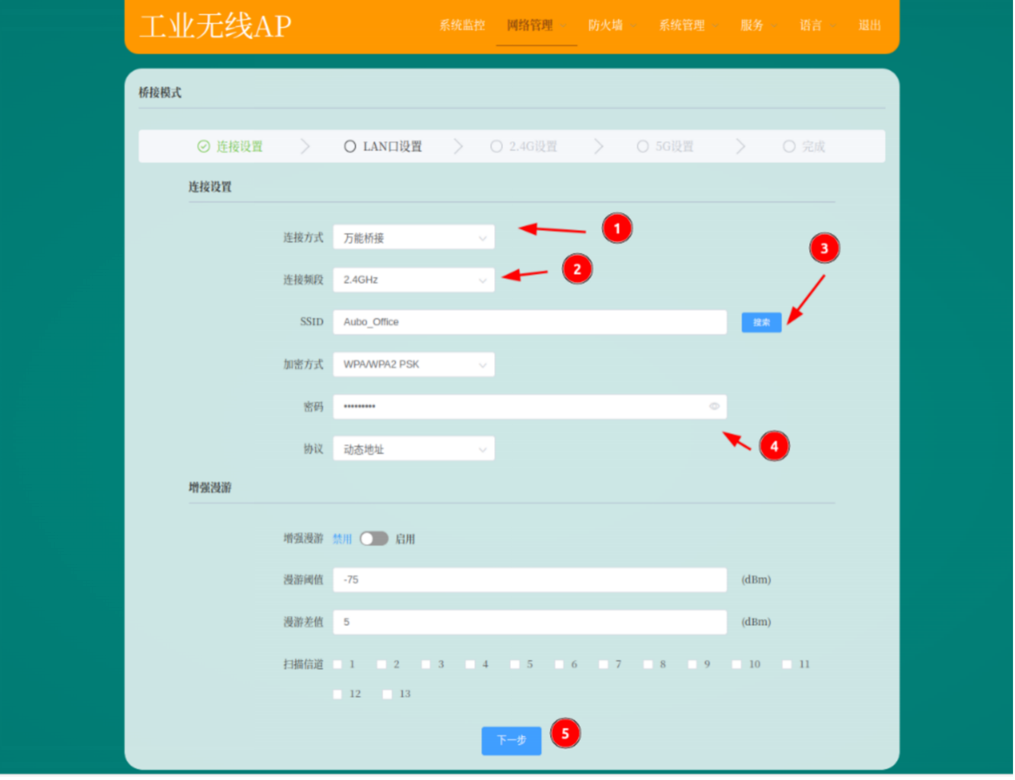
Search for the local Wi-Fi network, then enter the password and connect.
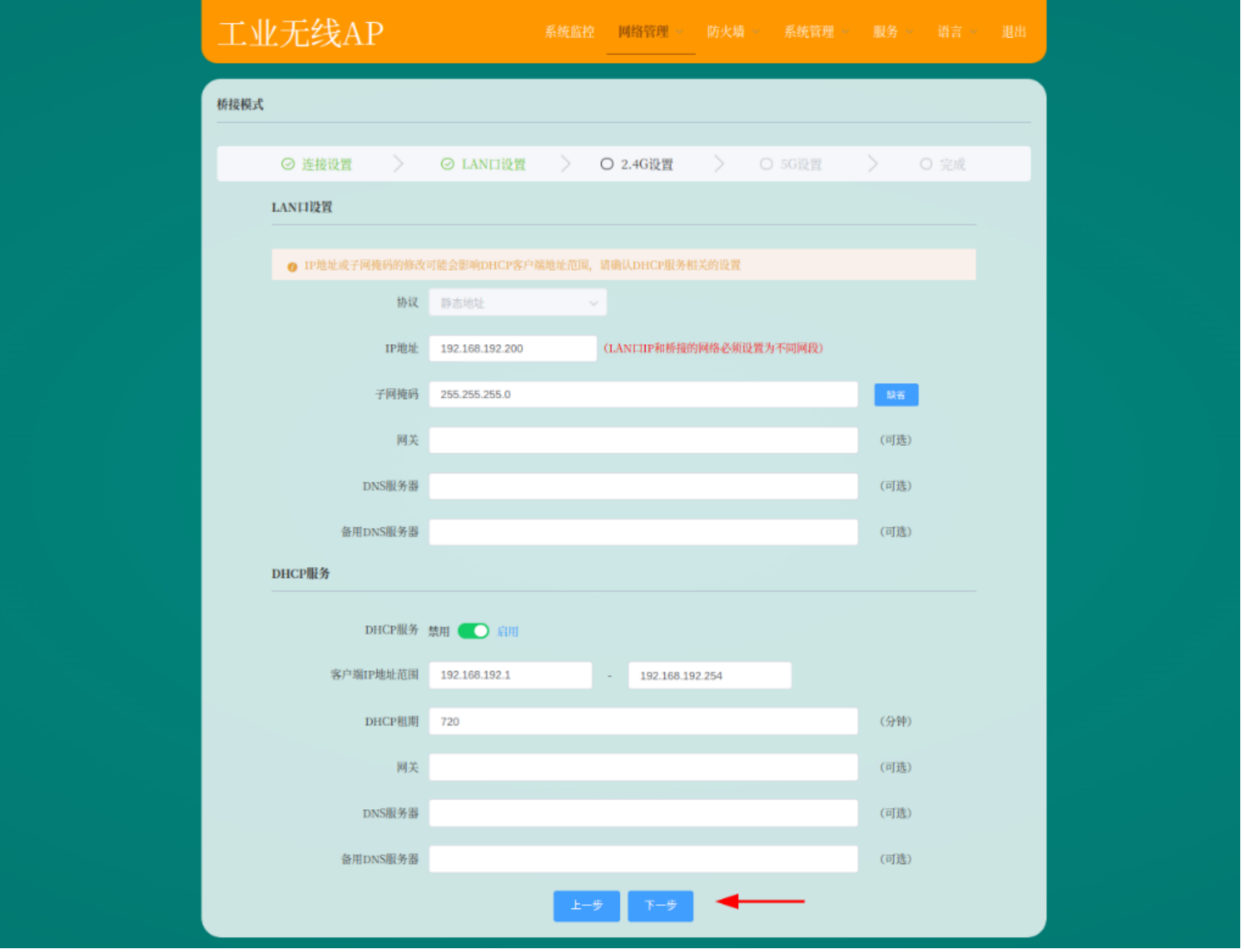
Configure the IP address and DHCP service as shown in the figure below.
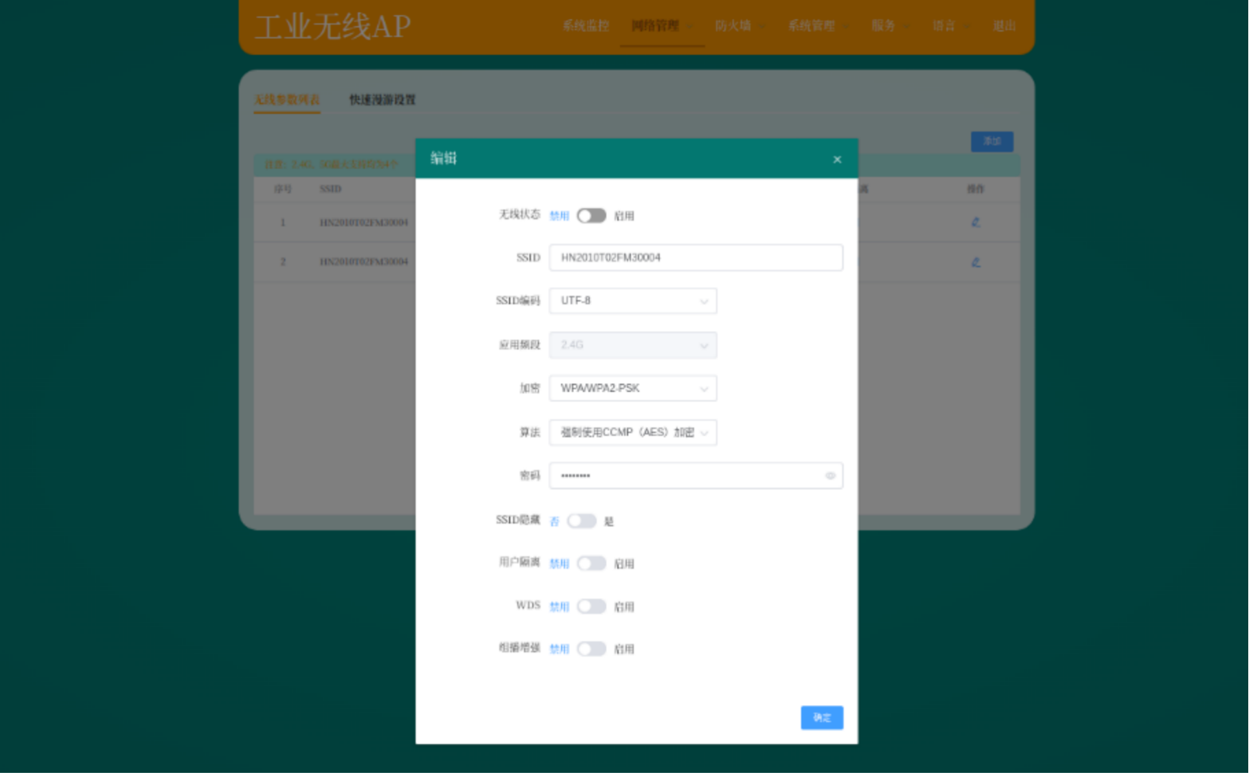
Set the SSID to the vehicle's SN code and the password to 12345678.
Similarly, you need to set the SSID to the SN code and the password to 12345678.
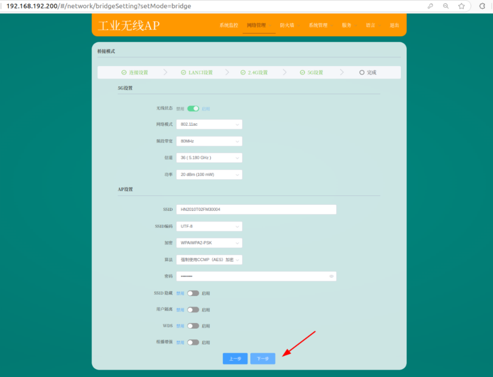
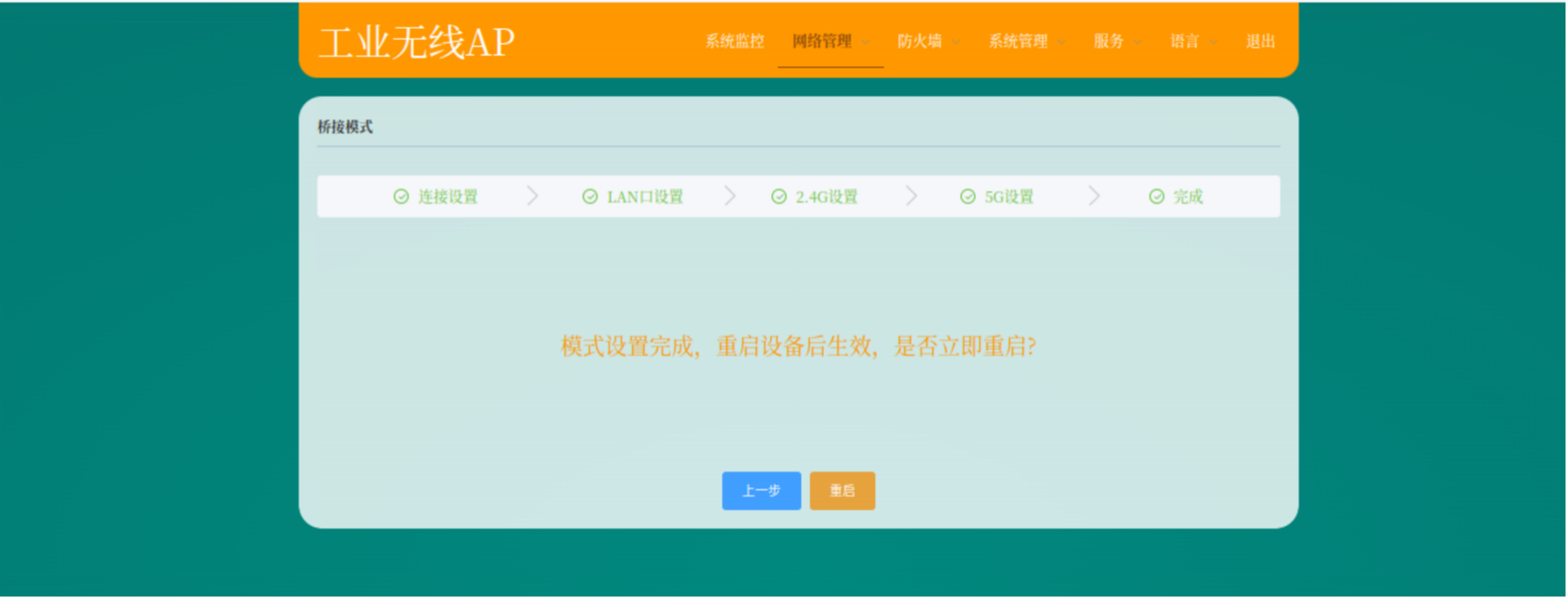
After confirming that the settings are correct, click "Restart":
If you are connected to a 5G band network, you need to disable the 5G band hotspot.


Note:
The band to be disabled here depends on the connected Wi-Fi. If you are connected to 5G, disable 5G.
6 Laser calibration
6.1 Preparation before calibration
Confirm that the basic functions of the vehicle are normal.
The vehicle has passed system tests and the program can be used normally. All nodes are running normally. The vehicle can be moved and used.
Replace the agvc.toml file.
bashcd /opt/agvc_ws/install/agvc_bringup/share/agvc_bringup/config cp agvc.toml /root/agvc/configStart the "laserodomcalibration" node.
Open a terminal and enter:
bashcd /opt/agvc_ws source install/setup.bash ros2 launch laser_odom_calibration laser_odom_calibration.launch.py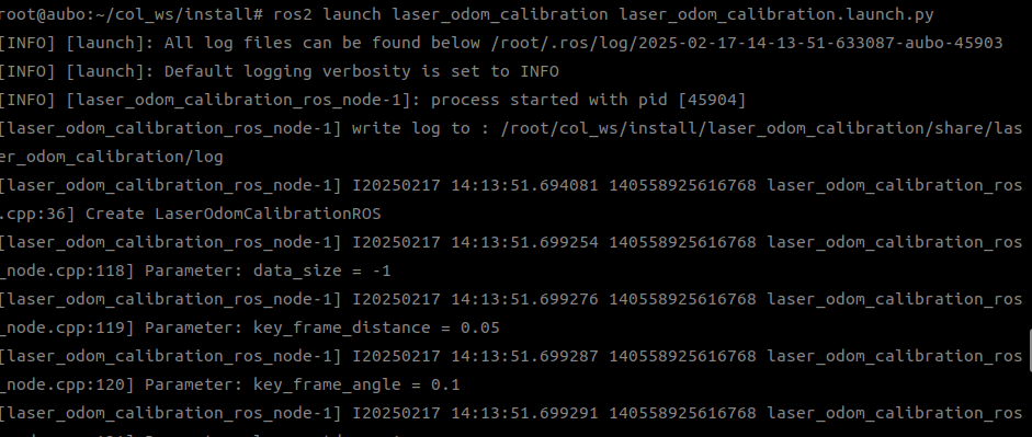
Start the "autocalibration" node.
Open a new terminal and enter:
bashcd /opt/agvc_ws source install/setup.bash ros2 launch auto_calibration auto_calibration.launch.py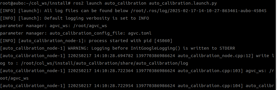
6.2 Start Calibration
Collect data Open a new terminal and enter:
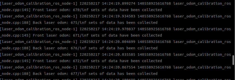
bashcd /opt/agvc_ws source install/setup.bash ros2 service call /auto_calibration/calibration_command agv_calibration_msgs/srv/CalibrationCommand "command: 2"Manually control the AGV to move in a 8-shaped pattern. You will see that the first terminal you started keeps refreshing. When the amount of calibration data exceeds 2,000, the data collection is complete.
Perform calibration Enter the following in the terminal:
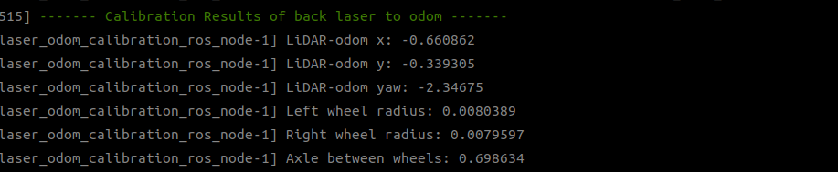
bashcd /opt/agvc_ws source install/setup.bash ros2 service call /auto_calibration/calibration_command agv_calibration_msgs/srv/CalibrationCommand "command: 4"After the calibration is complete, you can see the results, as shown in the figure below.
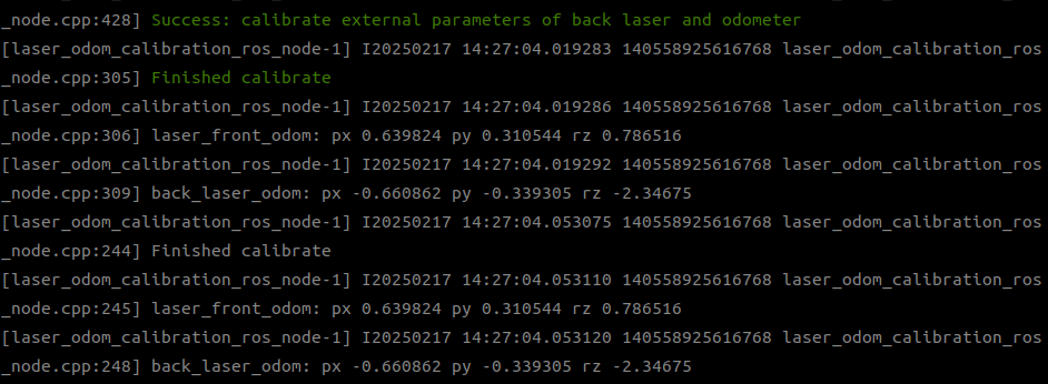
Compare the parameters. Check if the "left wheel radius" and "right wheel radius" of the front and rear lasers are similar.
 bash
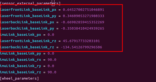
bashcd /root/agvc/config vim agvc.tomlCheck if the data has been written to the terminal.
6.3 Verification of calibration results
- Check whether the laser data from the front and rear lasers overlap;
- Check whether the values are close to the set values; Restart the equipment after the calibration is complete.
7 Map building
7.1 Map scanning
Connect the equipment
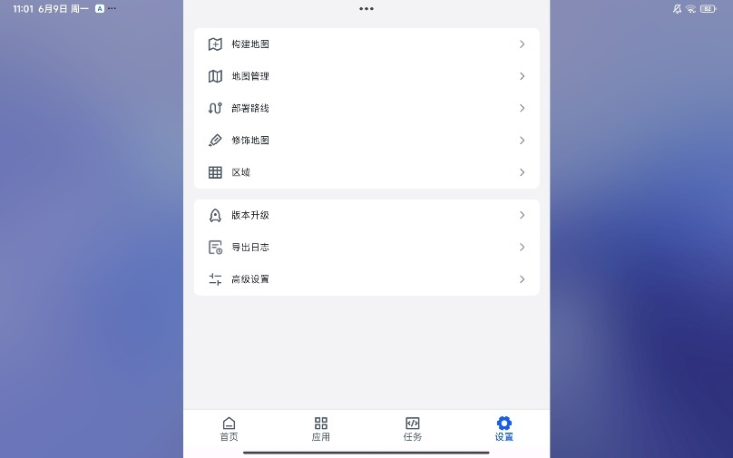
Click "Settings" and then "Build Map" to enter the map building mode.

Click "Start Building".
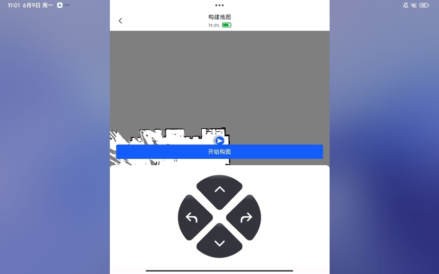
Move the AGV with open-loop control to scan the surrounding environment and form a closed loop.
Click "OK" to save the map.
7.2 Station and path configuration
Click "Settings" and then "Deploy Path" to enter the map editing mode.
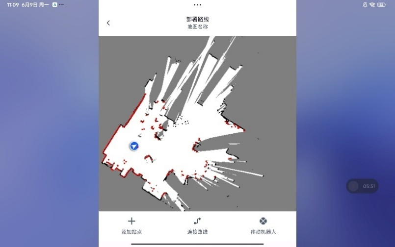
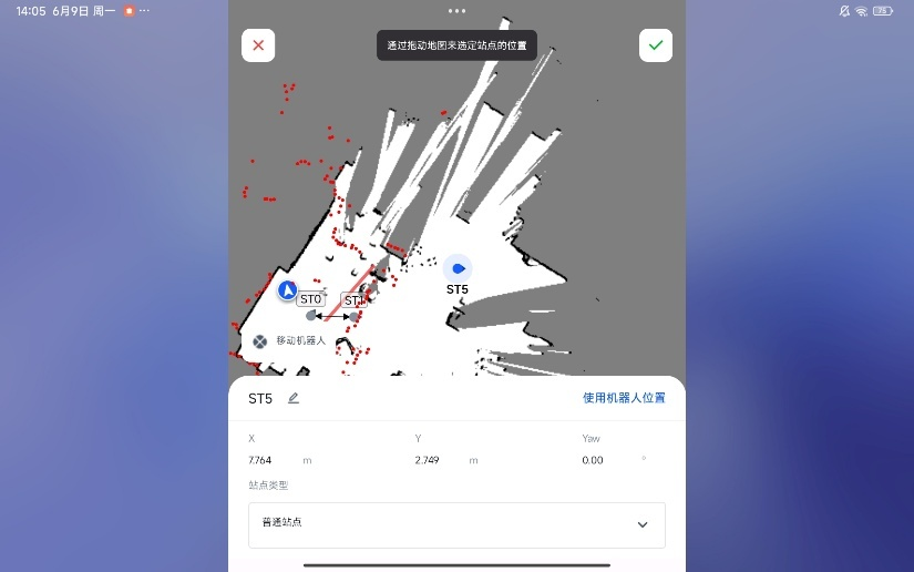
Click "Add Waypoint" and set it using the robot's current position or by manually entering coordinates.
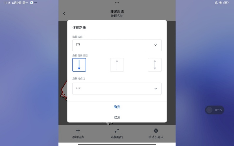
Click "Path", set the start and end stations, and select the path type.
8 Debugging of vision calibration plugin
8.1 Basic instructions
8.1.1 Description of each folder
The working directory of the vision server is /root/visual_position_ws.
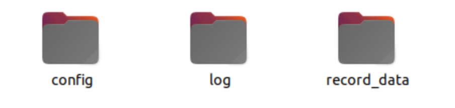
Working directory structure:
- Stores configuration files
- Stores log information
- Stores images and data captured in debug mode
8.1.2 Description of configuration file
visual_position.toml
version = "0.0.1"
virtual_env = false

# Camera parameters: intrinsic matrix, distortion coefficients, reprojection error
camera_intrinsics = [5276.246250, 0.0, 1607.094121, 0.0, 5275.387485, 1092.866504, 0.0, 0.0, 1.0]
camera_distortion = [0.001934, 0.070549, 0.003559, 0.002654, 0.000000]
re_projection = 0.21

# Hand-eye calibration parameters: eye-in-hand flag, rotation matrix, translation vector
eye_in_hand = true
hand_eye_R_cam2gripper = [0.026434, -0.999641, -0.00437334, 0.999568, 0.0264877, -0.0127271, 0.0128384, -0.00403502, 0.999909]
hand_eye_t_cam2gripper = [0.0849458, -0.000530306, -0.00371018]

# Charuco board parameters
squares_x = 5
squares_y = 7
square_len = 0.004
marker_len = 0.0024
refine = false
dictionary = "DICT_4X4_50"

# Aruco board parameters
arucos_x = 5
arucos_y = 7
aruco_len = 0.0032
aruco_interval = 0.0008
refind_strategy = true
aruco_dictionary = "DICT_6X6_250"

debug_data = false
8.2 Troubleshooting of common issues
Confirm whether the camera is working properly
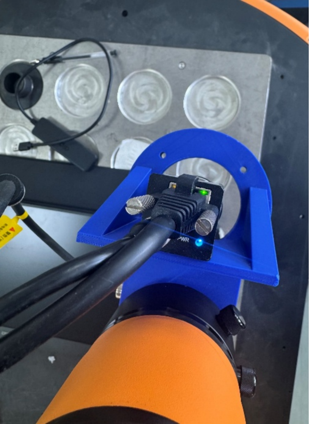
After the AGV is powered on, the camera's signal indicator lamp will flash as shown in the figure below. If the blue PWR indicator lamp is flashing, it means the camera is capturing images normally.
If the status is incorrect, you can check whether the camera driver has started normally:
bashsudo ps -aux | grep hik_camera_driver_nodeDuring visual grasping, the camera occasionally fails to recognize the object at the photo-taking position Troubleshooting:
Visually estimate whether the camera's current field of view can cover the tag mark. If it indeed cannot capture the tag, it is an AGV locating accuracy issue.
If you estimate that the tag can be captured, keep the robot arm and AGV stationary at the current pose, access the AGV terminal, and enter the following command in the terminal:
bash# Charuco curl --request POST 'http://0.0.0.0:30210/jsonrpc' --data '{"jsonrpc":"2.0","method":"getCharucoPose","params":[[0.338422,0.0653555,0.346477,-3.1413,0.001363,-0.0482567]],"id":0}' # Arucoboard curl --request POST 'http://0.0.0.0:30210/jsonrpc' --data '{"jsonrpc":"2.0","method":"getArucoboardPose","params":[[0.338422,0.0653555,0.346477,-3.1413,0.001363,-0.0482567]],"id":0}'If a result can be obtained, it may be because the photo was taken before the robot arm had moved into position. In this case, you need to add a delay, such as x, before the visual positioning node.
If no result is obtained, it means the tag cannot be recognized at the current pose, and you need to re-teach the photo-taking point.
9 Modbus communication
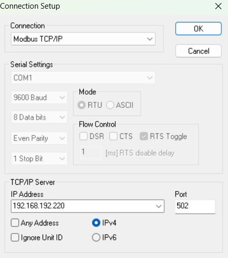
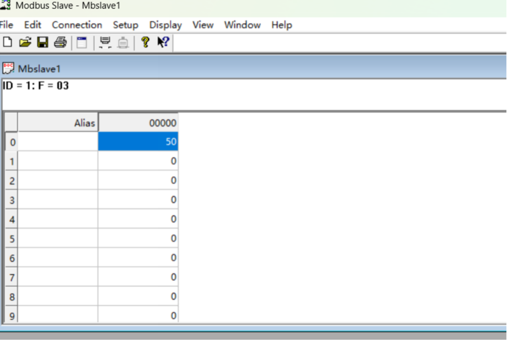
Download the Modbus Slave software on your computer to simulate a Modbus slave station.
Connect Modbus Slave, set the local IP address, and set the port number to 502.
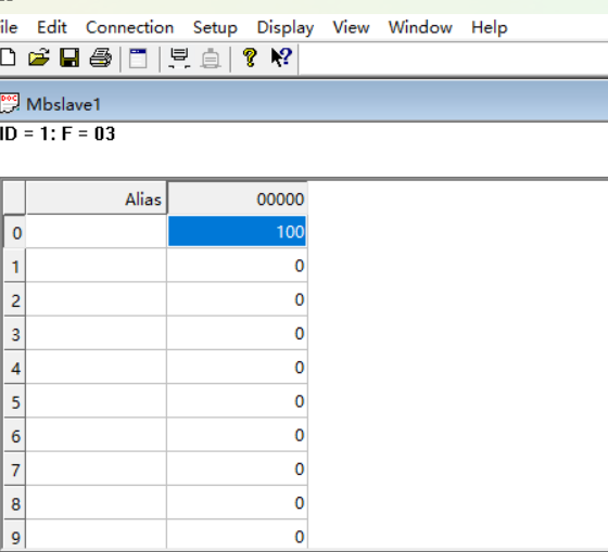
Set the address value, for example, set the value at address 0 to 100, and the register type to 03 Holding Register.
Establish a ModbusTCP connection on aubostudio, with the APP acting as the master station for connection to the computer slave station.
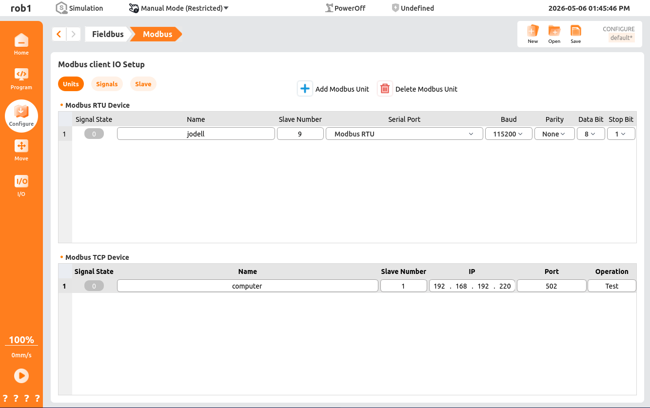
Set the signal to read address 0 of the holding register.
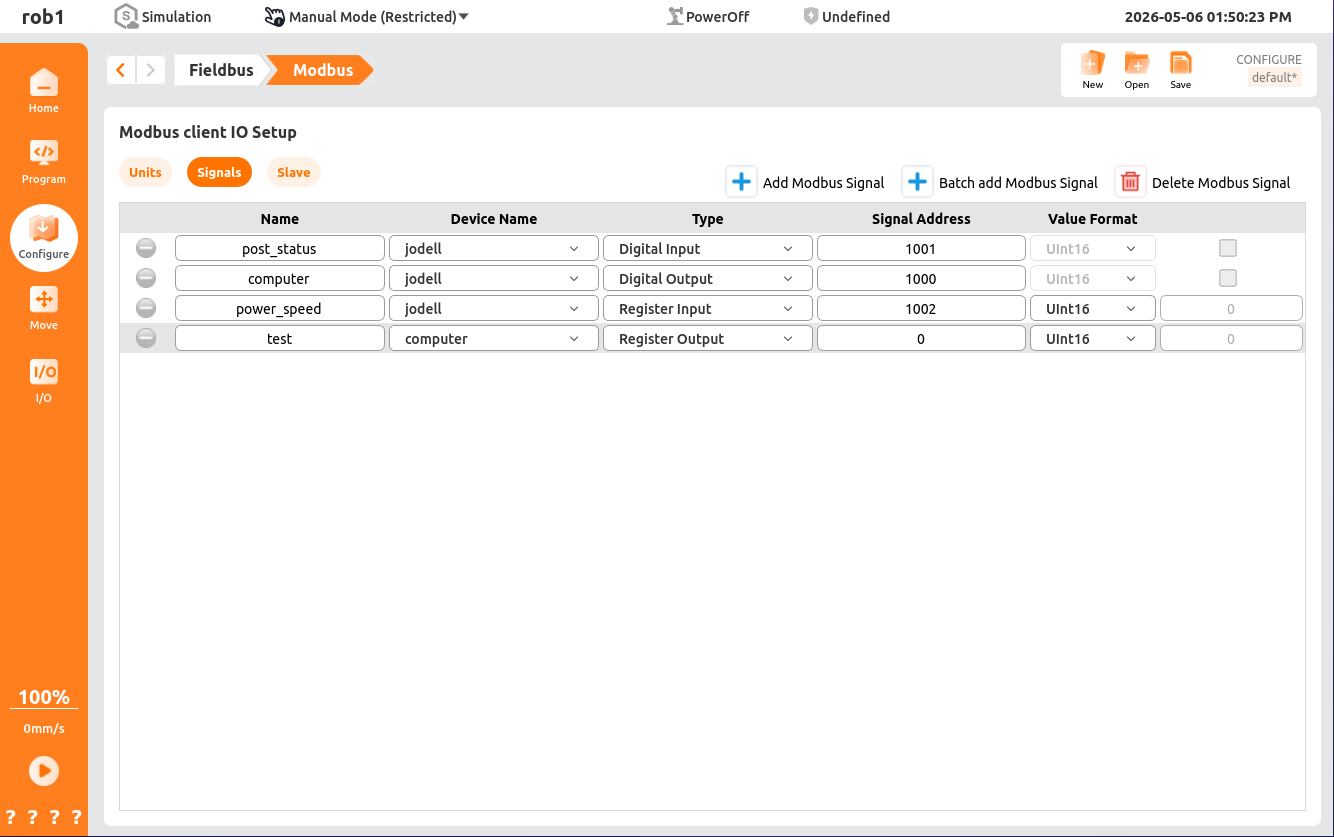
Set the signal value to 50.

01 Coil Register, 02 Discrete Input Register, 03 Holding Register, 04 Read-only Register. These four types of registers are used in the same way. Registers 01 and 03 are readable and writable, while registers 02 and 04 are read-only.
10 Communication configuration of electric gripper
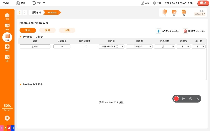
Here, Jodell gripper RG75 is used as an example.
Connect the gripper hardware to the composite robot.
Set the modbusRtu configuration:
Set the modbus signal:
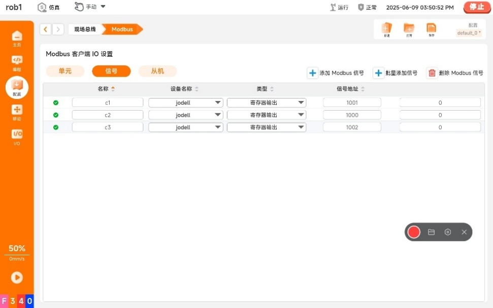
- c1 represents the gripper status and position status function.
- c2 represents the gripper enable and initialization function.
- c3 represents the gripper setting and force function.
Note:
There is an anomaly in the modbusRTU setting name, so c1, c2, and c3 are defined to represent them.
In this address, one address represents 1 byte, and one status occupies half a byte. Enter 1 in c2 to start initialization. This step is mandatory. Then, enter 9 in c2, which represents opening at full speed, full force, and full range. It can be observed that the value of c1 is 255, and since the gripper is normal, the status is 0. Since the value is 255, it represents opening at full range. Convert to binary, then it is 00000000 11111111; convert to decimal, then it is 255. The value of c3 is 65535, which means values of both speed and force are 255. Its binary form is 11111111 11111111, which is 65535 in decimal.
11 Programming
Add plugin conditions for line tracking:
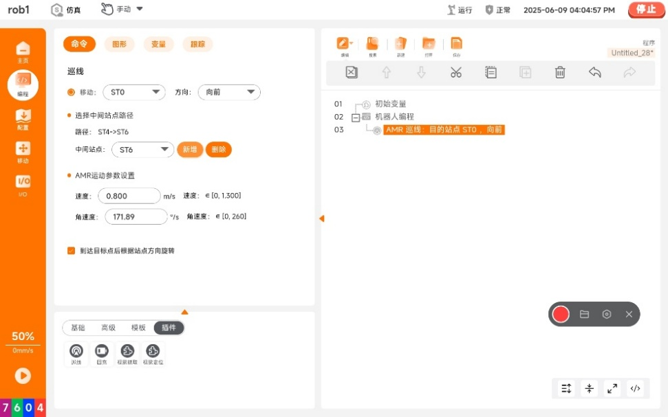
Select "Move", and set the target station and intermediate stations. All stations on the entire navigation path must be added, otherwise navigation cannot be performed.
Add visual positioning and select the corresponding ArUco code for recognition.
Add visual grasping to generate the corresponding condition tree:
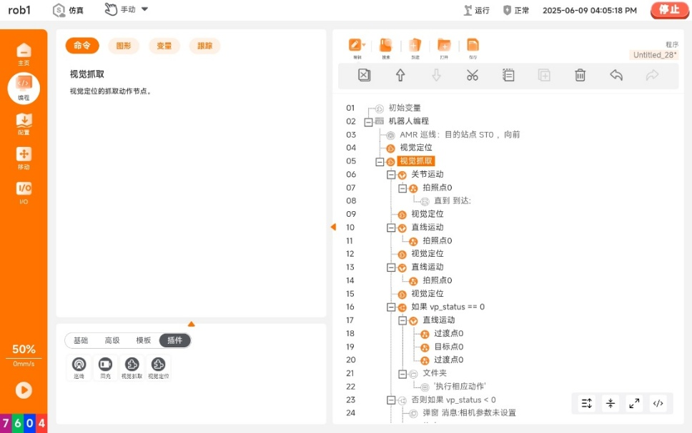
Set three identical camera points to take pictures. Then set the grasping point, which includes the target point and the transition point.