Operation Manual for AUBO Haina Series Composite Robot (Wireless Version)
1 About this manual
This manual covers the operation instructions for the supporting software of the AUBO Haina series composite robot. It is applicable to ARCS system version 0.31 and above. For ARCS system version information, please see the ARCS Teach Pendant Software User Manual.
The compatible composite robot model is AMR-300-S. For composite robot model information, please see the Product Manual for AUBO Haina Series Composite Robot.
This manual is for operation guidance only and does not serve as a guarantee of product functions and performance. For specific product functions and performance specifications, please refer to the actual product.
Copyright © 2015-2026 AUBO All rights reserved.
1.1 How to use this manual
This manual should be used when controlling and configuring the composite robot with software after the robot has been installed.
1.2 Target audience
This manual is intended for users of the AUBO Haina series composite robot (wireless version), such as customers, programmers, technical support personnel, and operators.
1.3 Operation prerequisites
Readers should have a basic understanding of the following: Basic knowledge of robot operation AUBO Scope
1.4 Related documents
- Product Manual for AUBO Haina Series Composite Robot
- ARCS Teach Pendant Software User Manual
2 Safety information
Users must read this manual carefully, especially the content marked with warning signs. The robotic system is complex and potentially dangerous. Operators must be fully aware of the operation risks and strictly adhere to all specifications and requirements in this manual.
2.1 Safety instructions
| Sign | Description |
|---|---|
 | A highly hazardous situation which, if not avoided, could result in death or serious injury. |
 | A hazardous situation which, if not avoided, could result in personal injury. |
 | A potential risk of equipment damage or data loss. |
 | Information that requires special attention. |
2.2 Personnel safety
Although the robot speed is controllable, danger may still arise during pauses and after stops in its movement due to its large mass and high torque. Although safety detection functions are available, the possibility of trajectory changes caused by external signals cannot be ruled out. Before operation, you must confirm that the emergency stop device is functioning properly. Before entering the work area, you must confirm that all safety measures are in place. Remain vigilant and strictly follow the safety rules during operation. Please remain vigilant at all times to ensure your own safety!
2.3 Safety rules
Before you start operating the robot, please ensure that you are familiar with the safety rules described in the Product Manual for AUBO Haina Series Composite Robot and the ARCS Teach Pendant Software User Manual. When using the software, please follow these basic principles:
- Ensure a stable operating environment to avoid unexpected power outages or network interruptions.
- Pay attention to the robot's status display and warning messages at all times.
2.4 Data security
To protect your program and configuration data:
- Regularly back up important robot programs and configurations.
- Do not modify system files and parameters arbitrarily.
- Before updating the software, it is recommended to back up the current configuration.
3 Overview
3.1 Introduction
The AUBO Haina series composite robot is an intelligent robot solution integrating multiple functions, designed for modern industrial automation environments. This series of products breaks through the application limitations of traditional robots, achieving unified control and collaborative work of collaborative robots, automated guided vehicles (AGVs), robot vision systems, and various end effectors. The all-in-one control system of the composite robot can be flexibly configured according to different working environments and application needs, greatly simplifying the operation process and lowering the barrier to use. Users can orchestrate complex workflows through the interactive interface, making industrial automation tasks more efficient, precise, and reliable.
3.2 Product list
The standard configuration of the AUBO Haina series composite robot includes the following documents:
| No. | Item name | Qty. |
|---|---|---|
| 1 | Product Manual for AUBO Haina Series Composite Robot 1 copy | 1 |
| 2 | Operation Manual for AUBO Haina Series Composite Robot (Wireless Version) 1 copy | 1 |
| 3 | ARCS Teach Pendant Software User Manual 1 copy | 1 |
| Tip | Description |
|---|---|
| The actual items received may vary depending on the product model and configuration. Please refer to the purchase contract. |
3.3 Version information
| No. | Version information | Version number |
|---|---|---|
| 1 | AGVC version | v0.6.3 and above |
| 2 | Steering client version | v1.0 and above |
| 3 | ARCS version | v0.31 and above |
| 4 | AUBO Scope client version | v0.9 and above |
4 Quick Start
Welcome to the AUBO Haina series composite robot. This series of robots is equipped with AUBO's latest ARCS system and uses the dedicated Steering client to control AGV functions. The teach pendant software of the ARCS system, AUBO Scope, provides powerful functions such as teaching and programming with a simple and intuitive interface, helping users quickly master the operation of the composite robot. This chapter will guide you through the initial setup and basic operations of the robot to help you get started quickly. For complete functional descriptions, please refer to the corresponding chapters.
4.1 Overview of operation process
The following table introduces the basic operation process for the AUBO Haina series composite robot, helping you quickly understand the overall operating steps.
| No. | Stage | Software tool | Key operations |
|---|---|---|---|
| 1 | System startup | - | Power on the robot and connect to an electronic mobile device |
| 2 | Map management | Steering | Build, apply, and decorate maps |
| 3 | Route planning | Steering | Deploy stations, plan routes, and set up zones |
| 4 | Task programming | AUBO Scope | Connect to the AGV, write programs, and execute tasks |
4.2 Operating steps
4.2.1 Preparation
Before starting the operation, please ensure that:
- The robot has a sufficient battery level.
- The electronic mobile device (such as a laptop) is functioning properly.
- The operating environment is safe, with no obstacles affecting the robot's movement.
- You have read the basic safety instructions.
4.2.2 System startup and connection
- Press and hold the robot's power button until the indicator light turns green, and wait for the system to start up.
- Turn on the electronic mobile device and connect to the robot's hotspot. For details, see "4.2 Connecting to the Robot".
4.2.3 Map management
- Open the Steering client and connect to the robot.
- Build a map: Go to "Settings > Build Map" and follow the instructions in "7.3 Building a map" to complete the map building. After completion, click the checkmark in the upper right corner to save.
- Apply a map: Go to "Settings > Map Management", select a built map, click "..." to rename it, and then click to use this map. For details, see "7.4 Map management".
- Optimize a map: Go to "Settings > Decorate Map" to check and adjust elements such as mobstacles and walls in the map. For details, see "7.6 Decorating a Map".
- Verify location: Go to the "Home" page and check if the robot location is accurate by viewing the location confidence in the monitoring area and observing whether most of the lidar point cloud falls on the walls. For relocation, see "7.2.2 AGV control functions".
4.2.4 Route settings
- Deploy stations: Go to "Settings > Deployment Route" to add the stations required for the robot to travel. For details, see "7.5 Deployment route".
- Set up zones: Go to "Settings > Zone" to add special zones such as virtual walls and slowdown zones to the map as needed. For details, see "7.7 Zone".
4.2.5 Program editing and execution
- Exit the Steering client, open the AUBO Scope client, and connect to the robot through the device list or by manually entering the IP address.
- Go to "Configuration > Plugin > AMR" to connect to the AGV.
- Open the "Programming" tab to create and edit program tasks.
- For an introduction to the basic programming nodes, see the ARCS Teach Pendant Software User Manual.
- For an introduction to the programming nodes of the AMR plugin, see "7.2 Programming".
- After programming, power on the robot, and then click the button in the left menu to execute the program.
5 Installation and connection
5.1 Client installation
Before starting the installation, please ensure that your mobile device meets the system environment requirements in "Appendix: Client Installation Environment Requirements". Please download the latest version of the client from the following official website channels:
AUBO Scope client download link:
Steering client download link:
5.2 Connecting to the robot
- Turn on the power switch of the robot. After the robot starts, the built-in Wi-Fi hotspot will be turned on automatically.
- Search for and connect to the hotspot of the robot.
- The default name of the hotspot is the SN of the robot (see the robot nameplate);
- Default password: 12345678.
- Start the client software and follow the on-screen instructions to complete the connection.
| Tip | Description |
|---|---|
| If you cannot find or connect to the hotspot, please try the following methods: 1. Check if the robot startup status is normal. 2. Try restarting the robot or the mobile device. 3. Check the distance between the device and the robot to ensure it is within the effective connection range. |
6 Operation instructions for AUBO Scope
AUBO Scope is a teach pendant software developed by AUBO specifically for the AUBO robot arm, used for robot arm control and programming. In the AUBO Haina series composite robot, in addition to the standard robot arm functions, AUBO Scope also supports interaction with the AGV system through the AMR plugin. For basic operations of AUBO Scope, see the User Manual of ARCS Teach Pendant Software. For detailed functions and usage of the AMR plugin, see "8. Operation instructions for AMR plugin (applicable to ARCS)" in this manual.
7 Operation instructions for steering client
Steering is a client software developed by AUBO specifically for the automated guided vehicle (AGV) of AUBO Haina series composite robots, used for AGV control and management. With Steering, users can build maps, deploy routes, monitor AGV status, and perform real-time control.
7.1 Interface overview
The Steering interface mainly consists of the following parts:
Operation area: Displays connectable robots, maps, and main operational content.
Navigation bar: Contains entries to each functional module.
7.2 Monitoring and control
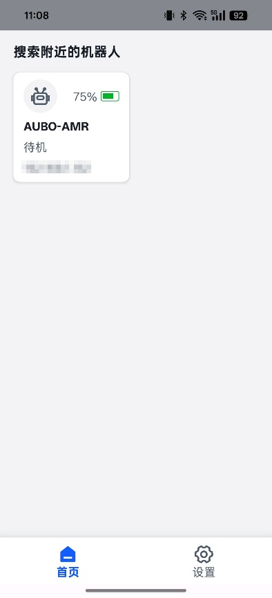
7.2.1 Home
The home page of the Steering client consists of the following parts:
Monitoring area: Displays AGV status information. Click this area to enter the map page to control the AGV.
- Red point cloud: Real-time detection data from the lidar.
Shortcut area: Contains function buttons.
- Start: Starts the AGV to execute preset tasks.
- Return to charge: Commands the AGV to return to the charging station.
- When battery level > 20%: Complete the ongoing mission and then return to the charging dock.
- When battery level < 20%: Abort the mission immediately and return to the charging dock.
Log area: Displays system operation records and AGV status changes.

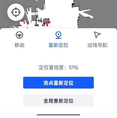
7.2.2 Control functions of AGV
Click the monitoring area to enter the map page, where you can use the following functions:
Movement: Control the movement of the AGV using the movement control keys.
Relocation: When the AGV's positioning is inaccurate, you can use the relocation function to correct its position.
Location confidence: The confidence of the AGV's current position on the map.
- Confidence >60%: positioning is reliable, and the AGV runs normally.
- Confidence <60%: positioning is unreliable, and the user needs to reposition the AGV.
- Confidence <25%: the confidence is too low, the AGV's position is seriously deviated, the AGV automatically stops moving, and the log reports an exception.
- Confidence >30%: the AGV resumes operation. 2. AGV location methods:
AGV location methods:
Point selection for repositioning: the user selects a position on the map, and the system will determine the AGV position near that point.
Global repositioning: the system automatically determines the AGV position on the entire map.
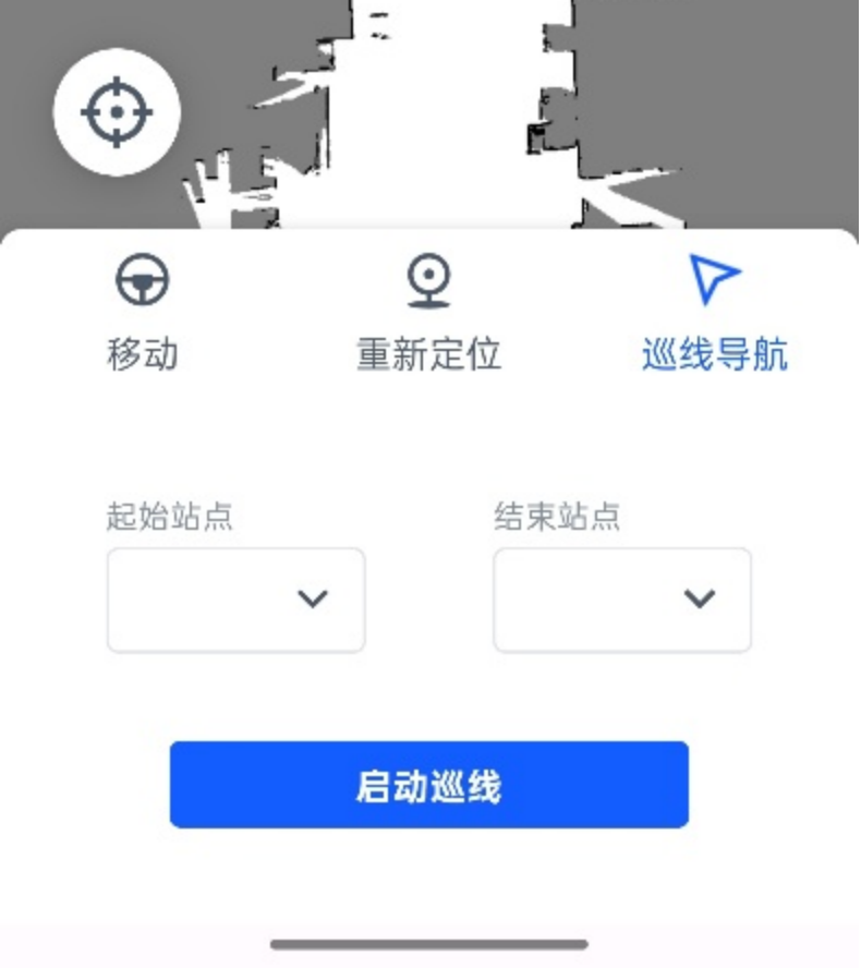
Cruise along guide line: Moves the AGV between two stations on a connected route. After two directly connected stations are selected as the start and end points, the AGV will automatically navigate along the preset route.
7.3 Map building
Map building is a fundamental step that must be completed at least once for using the robot for the first time or when the robot's operating environment changes. Steps:
- Click the "Start Building" button to enter the new map building page.
- Move the AGV using the control panel, then the system will automatically scan and record information about the surrounding environment.
- A concentric square-shaped route is recommended, where the AGV scans a full circle and returns to the starting point.
- After the map is built, click the check mark button in the upper right corner to save the map data.
Map element legend:
- Black line: Boundary of physical environments, such as walls and obstacles.
- White area: A scanned and traversable area.
- Gray area: An unscanned and unknown area.

7.4 Map management
The map management function is used to view and manage all created maps, supporting the following operations:
- Rename a map
- Delete a map
- Apply a map (switch the current map)

7.5 Route deployment
After a map is built and applied, you can set stations and connecting paths in "Route deployment".
| Tip | Description |
|---|---|
| The AGV can only move normally in a program task after a connecting path is established between two stations. |
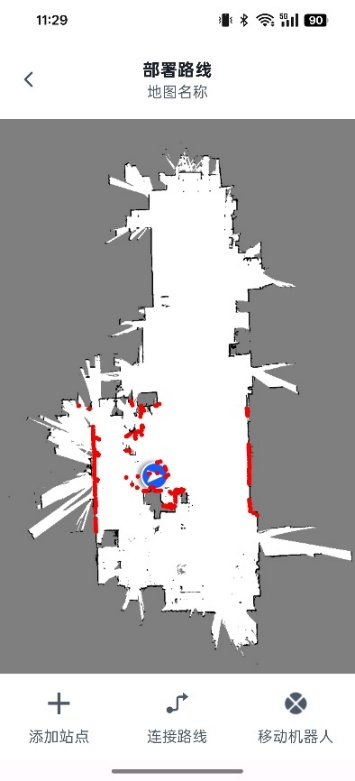
7.5.1 Station adding
Station type:
- Normal station: A general point for mobile targets.
- Charging station: A point where the AGV can be charged.
| Tip | Description |
|---|---|
| When setting up a charging station, ensure that the distance between the front of the AGV and the charging pile is between 0.5 and 1.5 meters, and that the charging port must be aligned with the charging pile. |
How to add:
- Click "Add Station".
- Drag the map to select a location, or move the robot to the specified location and then click "Use robot location" to confirm the station's position.
- Edit the station name and type.
- Click the check mark in the upper right corner to save the station.

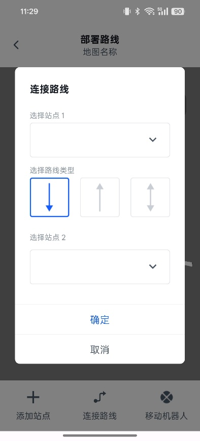
7.5.2 Route connection
Navigation between two stations is only possible after a route has been connected. Steps:
- Select the two stations that need to be connected by a route.
- Select the route type.
- Click to add the route.
Route editing:
Select a connected route to edit its name and type.
Click to adjust the path shape (straight line, Bessel).
7.6 Map decoration
After creating a map, you can manually decorate and adjust its details.
- Black pen: Adds boundaries.
- Gray pen: Adds unknown areas.
- Eraser: Adds traversable areas.

7.7 Area
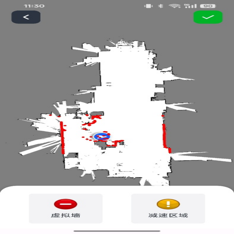
You can add special areas to the map:
- Virtual wall: Sets an area that the AGV cannot pass through, which is only effective during free navigation.
- Deceleration zone: Sets an area where the AGV must pass at a low speed. The AGV's travel speed can be customized.
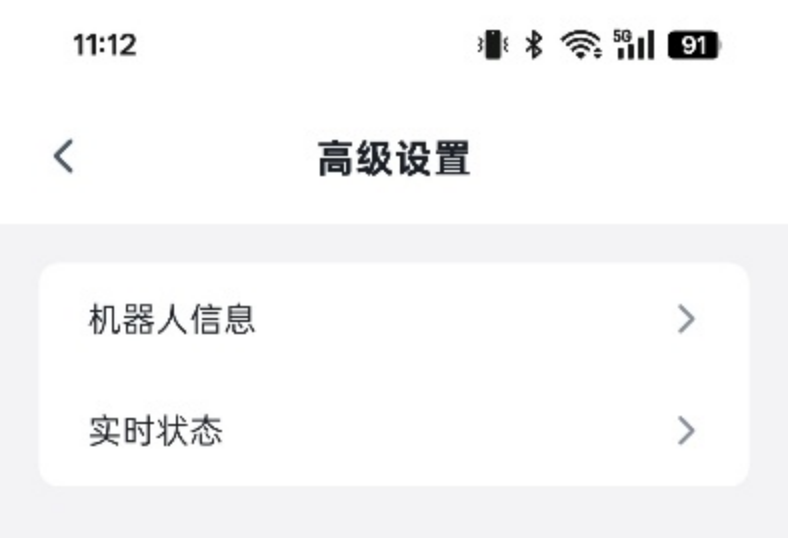
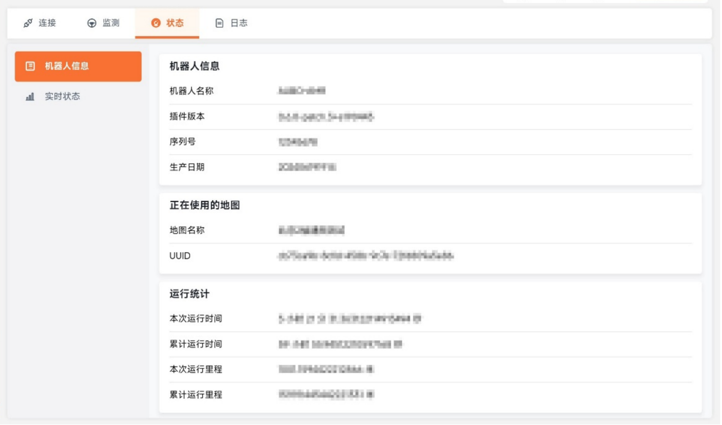
7.8 Advanced settings
You can view the detailed information and real-time status of the AGV, including equipment information, AGVC version information, operating statistics, and real-time status parameters of the AGV.
8 Operation instructions for AMR plugin (applicable to ARCS)
The AMR plugin is a functional module in the ARCS system used to manage and control automated guided vehicles (AGVs), providing functions such as monitoring, status and log viewing, and task programming.
8.1 Configuration
8.1.1 Interface overview
The AMR plugin interface consists of the following parts:
Navigation bar: Function tabs such as Connection, Monitoring, Status, and Log.
Operation area: The main area for displaying the map and robot status.
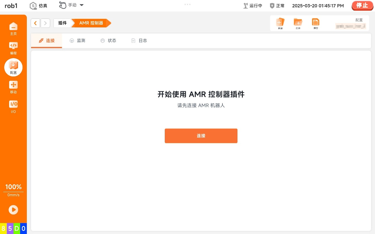
8.1.2 Connection
Before using the AMR plugin, you need to connect the target AGV first.
| Tip | Description |
|---|---|
| Be sure to connect the AGV first to obtain data such as maps and stations configured in the Steering client. All monitoring and control functions depend on this connection. |
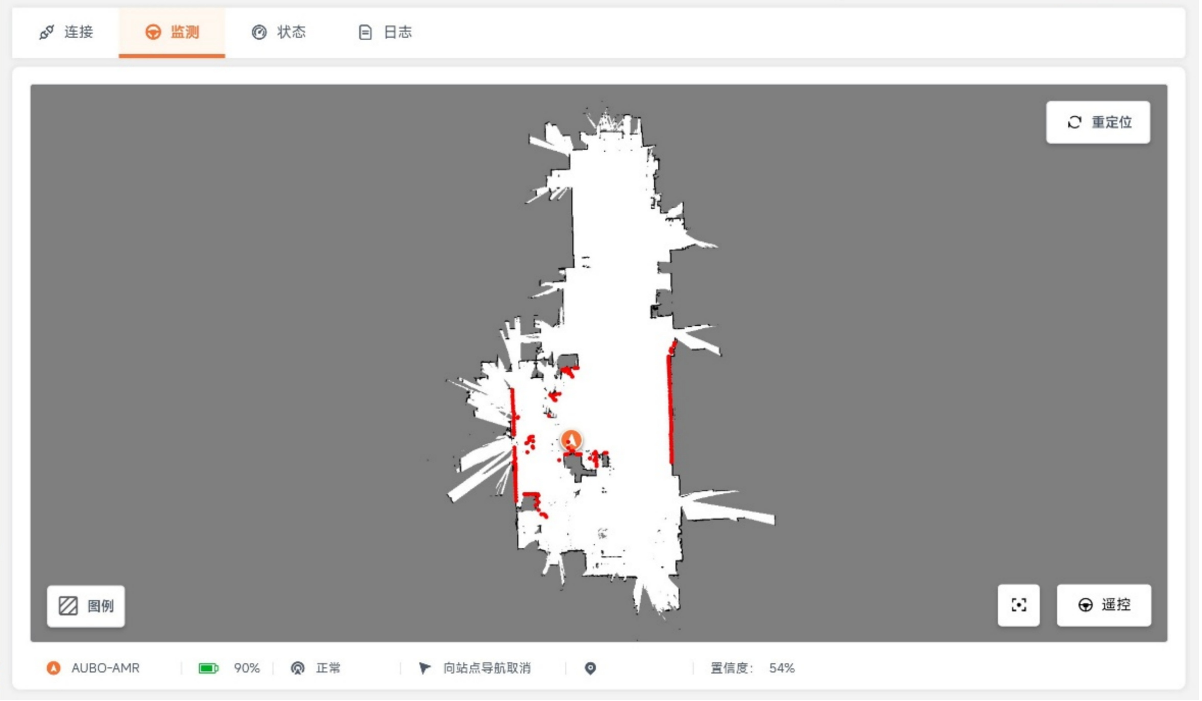
8.1.3 Monitoring
The monitoring function is used to observe and control the position and status of the AGV on the map in real time. Map operation functions:
- Relocation: When the AGV's positioning is inaccurate, click this button, then the system will automatically search for and correct the robot's location.
- Reset: Resets the map that has been zoomed or panned to its default position and size.
- Remote control: Activates the AGV's movement control keys, allowing you to manually control the robot's movement.
Map legend:
- Waypoint: A station that the AGV can pass through, which can be used as a node and destination for path planning.
- Charging point: A station where the AGV automatically returns to charge, which can also be used as a waypoint.
- One-way line: A path where the AGV can only travel in the direction indicated by the arrow.
- Bidirectional line: A path where the AGV can travel in both directions between two connected stations.
- Deceleration area: After entering this area, the AGV will automatically reduce its speed to a preset value.
Status bar information of the AMR plugin:
- AGV name: The name of the currently connected AGV.
- AGV battery level: The current battery level.
- AGV status: The current operating status of the AGV.
- Task status: The execution status of the current task.
- Positioning status: The current location status.
- Location confidence: The confidence of the AGV's current position on the map.
8.1.4 Status
On this page, you can view the detailed information and real-time operating parameters of the AGV. The content is the same as in "7.8 Advanced settings".
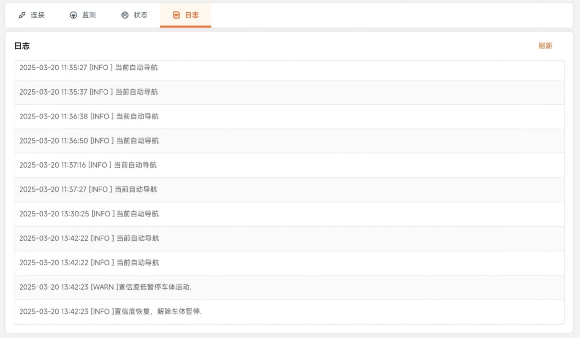
8.1.5 Log
The log function is used to view and analyze various event records during AGV operation.
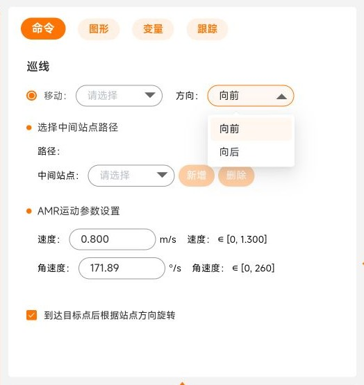
8.2 Programming
8.2.1 Line following
The "Line following" node in programming is used to configure the AGV's movement path in the program. Configuration options:
- Movement: Select this option to choose the target station and moving direction.
- Select intermediate stations: You can select the stations that the AGV needs to pass through on its way to the target point.
- AGV motion parameter settings: Set parameters such as the AGV's moving speed and angular velocity.
- Rotate according to the station direction after arriving at the target point: If this option is checked, the AGV will automatically adjust its orientation to the preset direction of the station when it arrives at the destination station.
8.2.2 Recharge
The "Recharge" node in programming is used to configure the trigger and completion conditions for the AGV's automatic charging behavior.
- Minimum value: Set the battery level threshold (percentage) to trigger charging. When the AGV's battery level is below the minimum value, the AGV moves to a charging station to charge.
- Maximum value: Set the battery level threshold (percentage) for charging completion. When the AGV's battery level reaches this value, the AGV leaves the charging pile and moves to a specified location to continue its tasks.
- Charging point: Select a specified station, then the AGV will go to that charging station to charge; set "Auto select", then the AGV will go to the nearest charging station.
- Standby point after full charge: Select a specified station, then the AGV will automatically navigate to the specified station and wait on standby after charging is complete; if you set "Not set", the AGV will automatically return to the current charging station and wait on standby.

| Tip | Description |
|---|---|
| It is recommended to set the minimum value to 20% or higher to ensure that the AGV has enough battery level to travel to the charging station. |
9 Appendix: Client Installation Environment Requirements
| Name | Requirement |
|---|---|
| Operating system | Android 9 and above |
| CPU | 2.0 GHz (quad-core) and above |
| Memory | 4 GB and above |
| Screen resolution | 1920×1080 and above |