ARCS Modbus User Guide
1.Modbus TCP and Modbus RTU Introduction
Modbus is a serial communications protocol originally designed by Modicon (now Schneider Electric) in 1979 for automation equipment using programmable logic controllers (PLCs).Modbus has become the de facto standard for communication protocols in industry.The Modbus protocol consists of two forms, Modbus RTU and Modbus TCP.
Modbus RTU(Remote Terminal Unit): This is a binary communication protocol based on serial lines (such as RS-485, RS-422, RS-232). In Modbus RTU, data is transmitted in binary form, and each byte is represented by two hexadecimal characters. Modbus RTU is mainly used in industrial and system automation applications, in which the communication distance between devices is long.
Modbus TCP (Transmission Control Protocol): This is an Ethernet-based Communication Protocol.Modbus TCP uses the TCP/IP protocol for communication and therefore can utilize the existing Ethernet infrastructure. Compared to Modbus RTU, Modbus TCP can support more device connections and faster communication.
The main difference between the two is the protocols for the physical and transport layers: Modbus RTU uses serial communication, while Modbus TCP uses the TCP/IP protocol.
2.Introduction
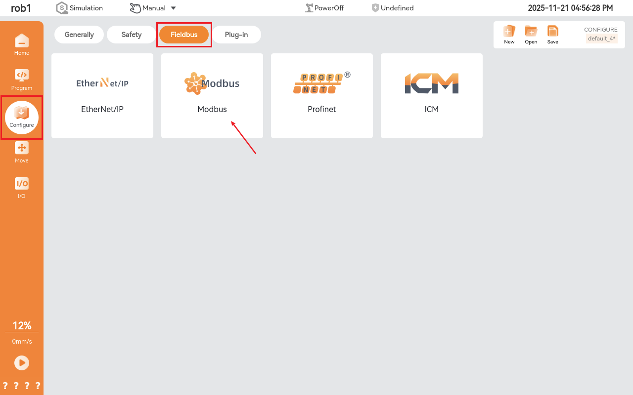
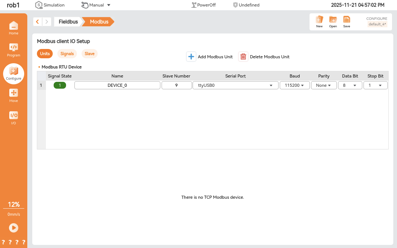
Open ARCS software, Modbus is located at Configuration > Fieldbus -> Modbus.
2.1 Modbus TCP
PS: Ensure that communication between the device and the robot is working and can be checked using the ping command, and that the device's firewall is turned off.
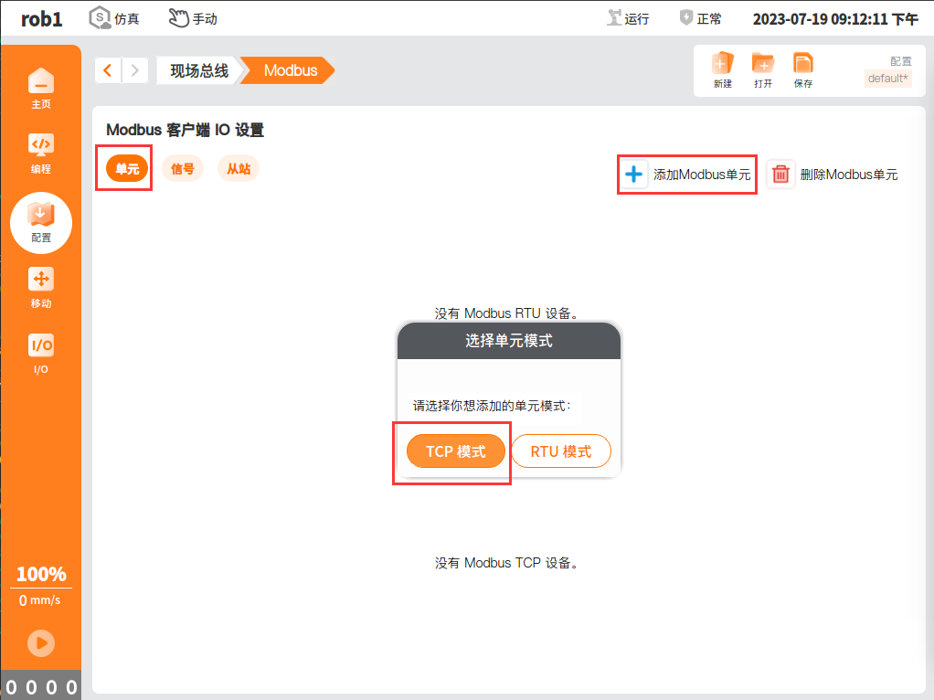
- On the Unit page, click Add Modbus Unit > TCP Mode.
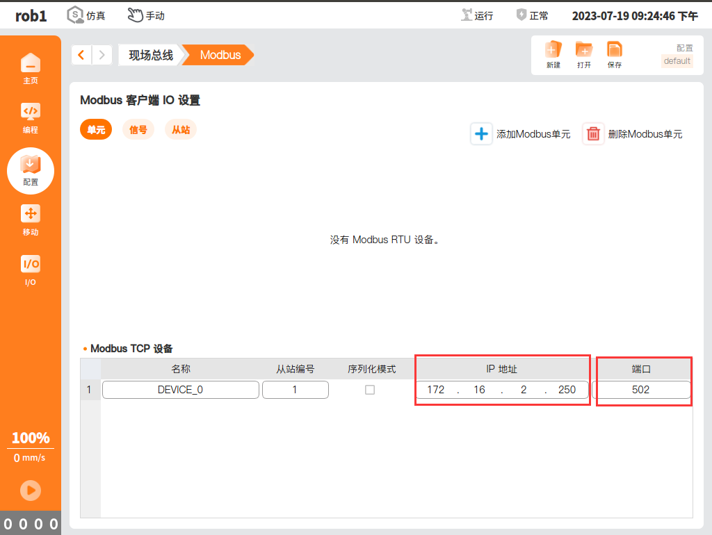
- Enter IP address and Port
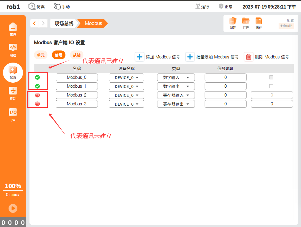
Signal page, select Add Modbus Signal.
1: COIL STATUS: Used to read and control the switching status of remote devices, usually used to control switching devices such as relays.
2: INPUT STATUS: Used to read the input status of remote devices, usually used to read the status of input devices such as sensors.
3: HOLDING REGISTER: Used to store and read the data of remote devices, usually used to store control parameters, device status and other information.
4: INPUT REGISTER: Used to store the input data of the remote device, usually used to store the data of the sensor and other input devices.
2.2 Modbus RTU
PS: Ensure normal communication between the device and the robot, use the serial port debugging assistant to test whether the line communication is normal.
- Units page, click Add Modbus Unit > RTU mode.
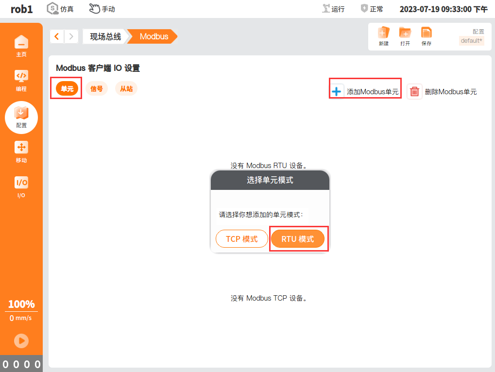
Select Serial port number > Baud rate > Parity > Data bit > Stop bit.
Note: If the communication is unstable and the signal status flashes, you can reduce the baud rate value (e.g., 9600, 4800).
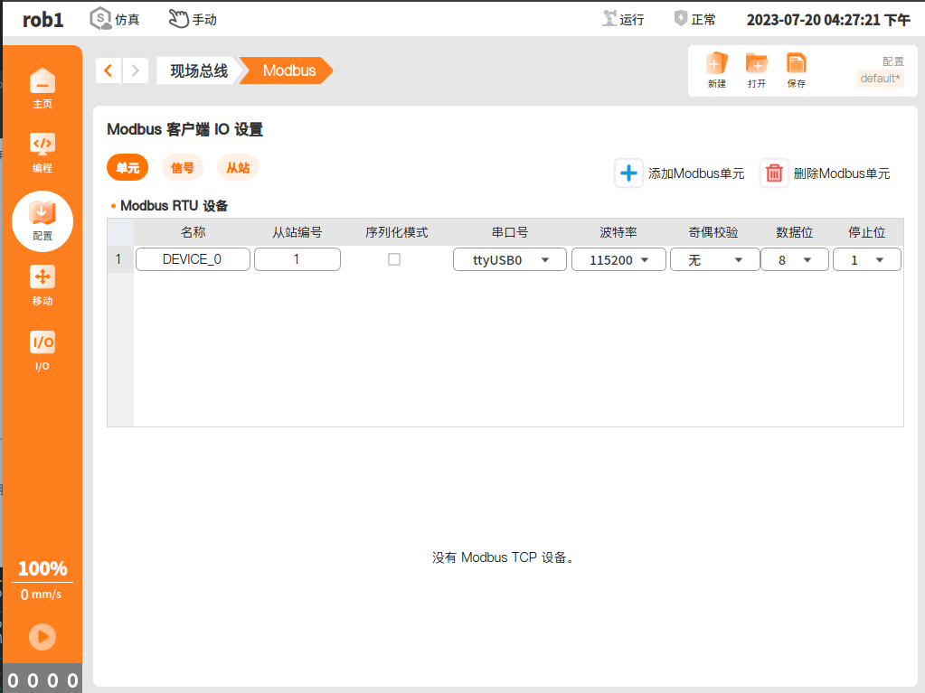
Signal page, select Add Modbus Signal.
1: COIL STATUS: Used to read and control the switching status of remote devices, usually used to control switching devices such as relays.
2: INPUT STATUS: Used to read the input status of remote devices, usually used to read the status of input devices such as sensors.
3: HOLDING REGISTER: Used to store and read the data of remote devices, usually used to store control parameters, device status and other information.
4: INPUT REGISTER: Used to store the input data of the remote device, usually used to store the data of the sensor and other input devices.

Use in if nodes
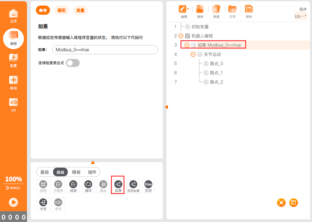
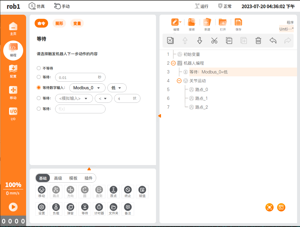
- Used in Waiting node
2.3. Problem Solving
Modbus TCP signal communication failed
- Check whether the network between the device and the robot can communicate normally, first check whether the firewall of the device is closed, and then use the
pingcommand to check whether the network can communicate normally; - Troubleshoot whether the signal address established by the master station exists in the slave station. The corresponding address of the newly created signal in the master station must exist in the slave station for the signal to communicate normally;
Modbus RTU signal communication failed
- Check whether the serial port communication between the device and the robot is normal, you can use the serial port debugging assistant in the device and the robot to test the serial port communication status;
- Check whether the signal address established by the master station exists in the slave station. The corresponding address of the newly created signal in the master station must exist in the slave station for the signal to communicate normally;
Operational Steps:
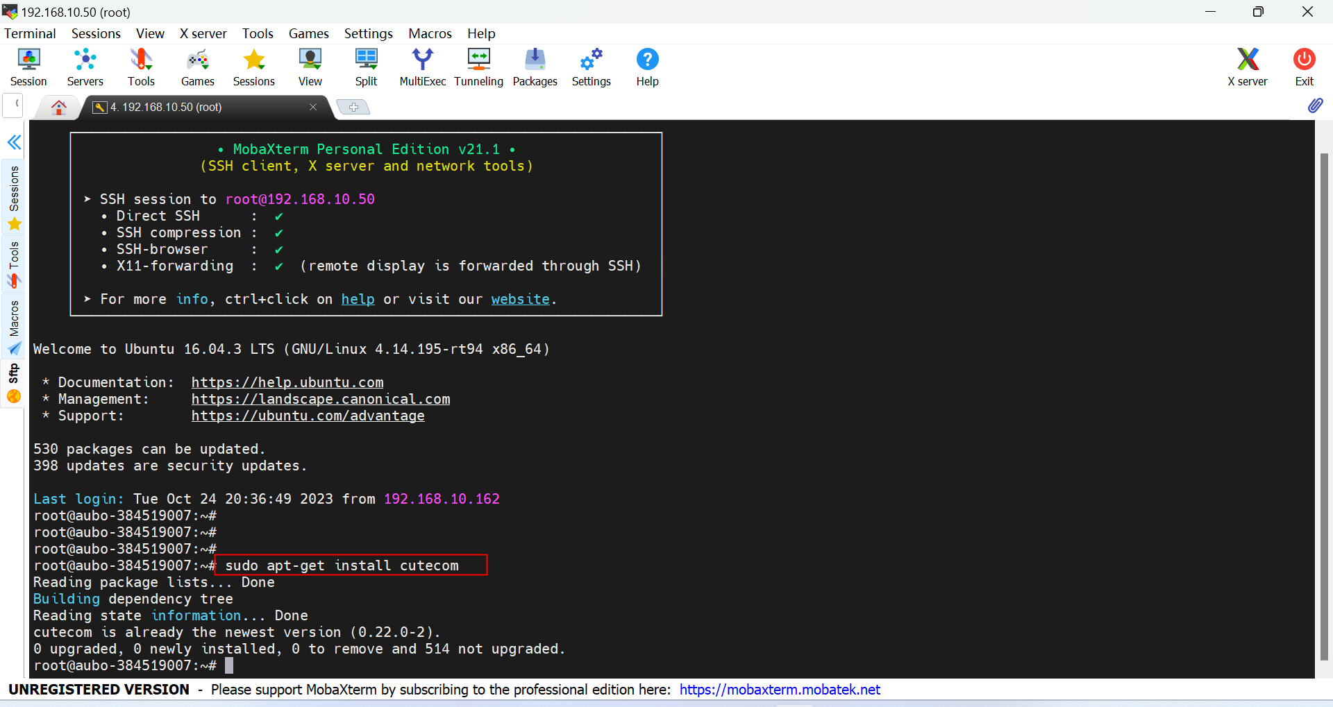
Install cutecom in the robot control cabinet using the command
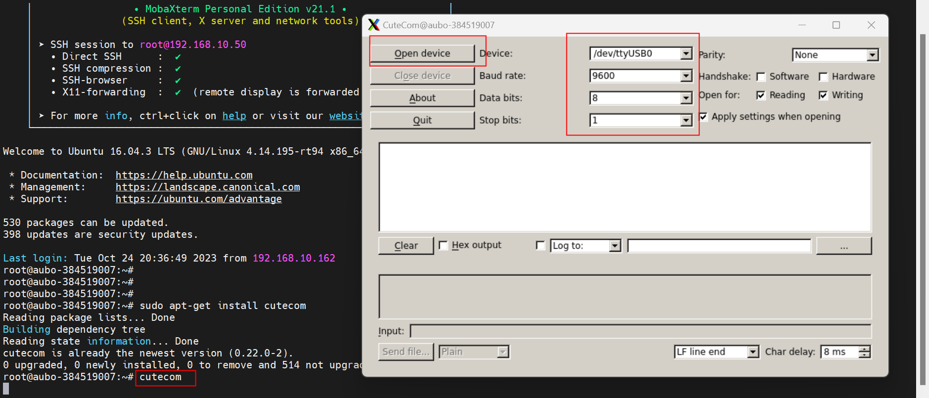
Open cutecom and set the serial port number, baud rate, parity, data bits and stop bits.
If the device is a PLC, use cutecom to connect directly to the PLC to test, if the device is a local computer, install the serial port debugging assistant in the computer, for example: XCOM. 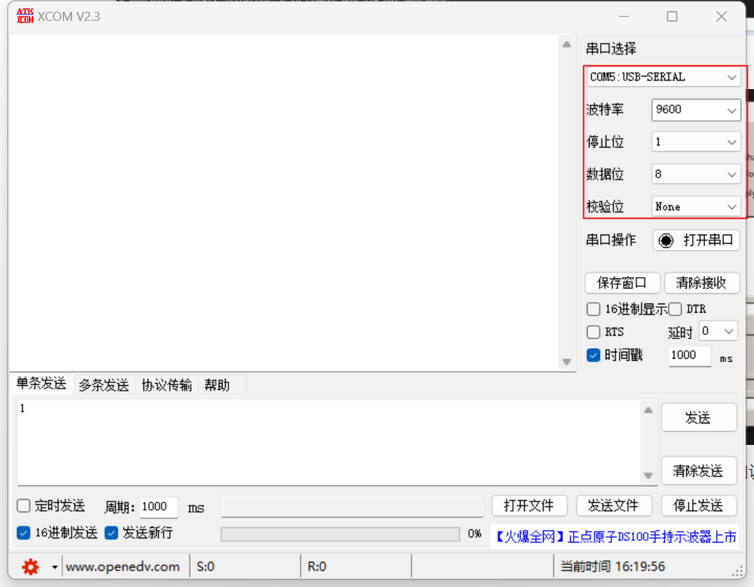
If cutecom and PLC/XCOM can send data to each other, it means that they can communicate normally and there is no problem with the serial communication line, otherwise, it is necessary to check the communication line connection;
3.The Modbus signal is used in the configuration
In Configuration-General-I/O Settings
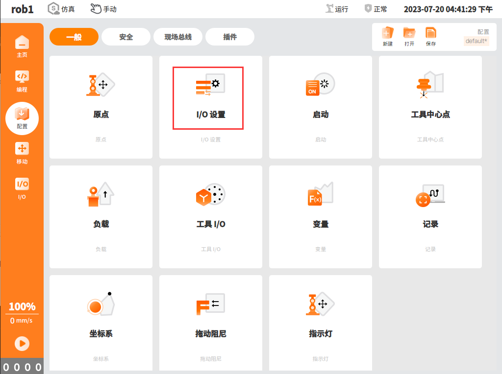
- Input action

- Output signal
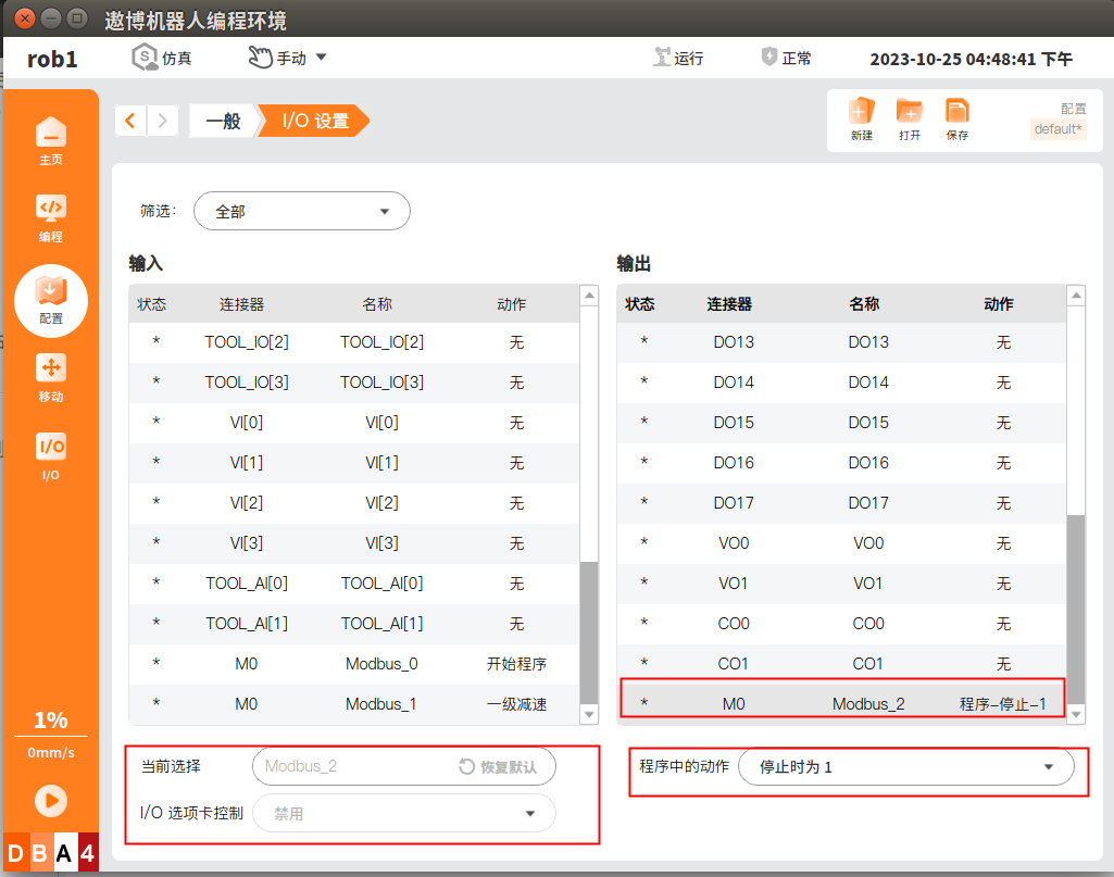
4. Modbus slave station
Step 1: turn on Modbus TCP or Modbus RTU;
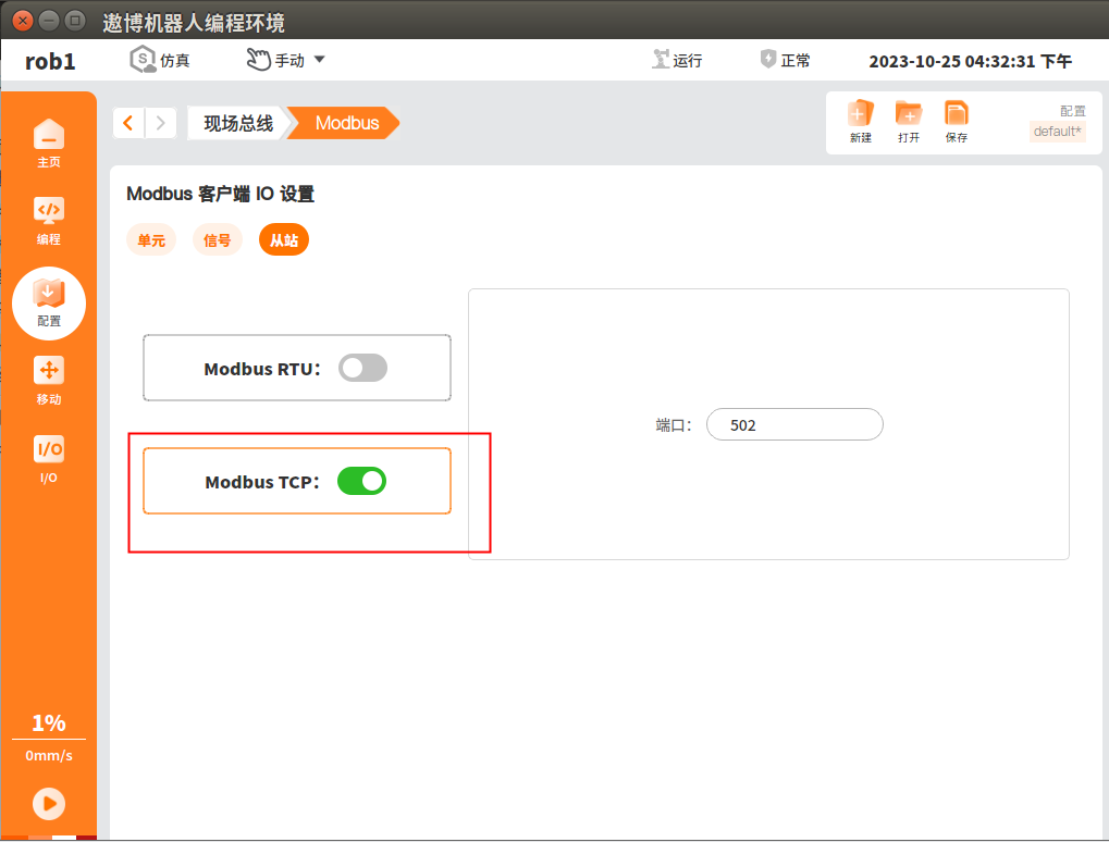
Step 2: After the slave station is turned on, other master stations (such as modscan) can be used to connect the slave station. Please refer to the definition in Modbus slave station agreement for the slave station address.
Note: For the solution to the communication problem of Modbus slave station, please refer to the above-mentioned communication problem handling steps of master station.
