ICM Gateway Service User Guide
1 Environmental configuration
1.1 Software and hardware description
(1) hardware gateway
voltage:12V~24V
electric current:0.5A~1A
(2) Botu Software
version:TIA Portal V16
(3) GSD file
GSDML-V2.41-AUBO-irj45-20230720.xml
(4) hardware PLC
S7-1200 CPU 1214C DC/DC/DC 6ES7 214-1AG
(5) Gateway Service Profile Description
The ICM service process configuration file is stored in /root/arcs_ws/config/aubo_icm.conf by default, which includes some necessary configurations for the use of the gateway process, set it up before using it, the specific options are as follows:
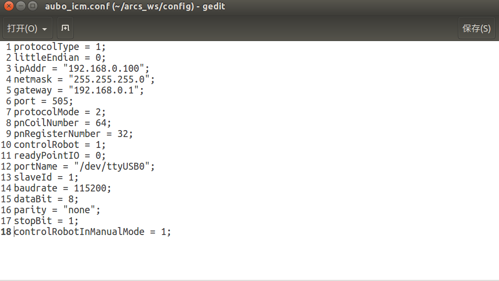
Configuration item description:
| Configuration | Description | Default Value | Required or Not |
|---|---|---|---|
| protocolType | Protocol Type: 1:Profinet,2:Ethernet/IP,3:EtherCAT; | 1 | required |
| littleEndian | Data storage format: 0:Big-Endian, 1:Little-Endian; | 0 | required |
| ipAddr | Gateway Module IP; | 192.168.0.100 | required |
| netmask | Gateway Module Mask; | 255.255.255.0 | required |
| gateway | Gateway Module Gateway; | 192.168.0.1 | required |
| port | Gateway Module Port; | 505 | required |
| protocolMode | Protocol Mode: 1 min mode,2 standard mode,3 custom mode; | 2 | required |
| pnCoilNumber | Number of coils; | 64 | required |
| pnRegisterNumber | Number of registers; | 32 | required |
| controlRobot | Control robot keywords: 0 not controllable, 1 can control the robot project start, pause and other functions. When the control project is started, it is necessary to judge whether the robot arm is at the ready point or not; | 1 | not |
| readyPointIO | Whether the mechanical arm has a preparation point.; | 0 | not |
| portName | Serial number of control cabinet equipment: /dev/ttyS*(If the control cabinet is connected via usb, check the current serial port number with the command ls /dev/ttyU*); | /dev/ttyS0 | required |
| slaveId | Slave number; | 1 | required |
| baudrate | baud rate; | 115200 | required |
| dataBit | data bit; | 8 | required |
| parity | parity check; | none | required |
| stopBit | stop bit; | 1 | required |
| controlRobotInManualMode | Controlling the robot in manual mode or not; | 1 | not |
Note: The above configuration of the gateway is the default setting, and the setting can be modified according to the actual situation. For example, the IP and station name of Profinet communication are usually set by software such as Boto, and the above configuration can be used directly without any change.
1.2 Gateway Wiring Introduction
1.2.1 Introduction to each hardware module of the gateway
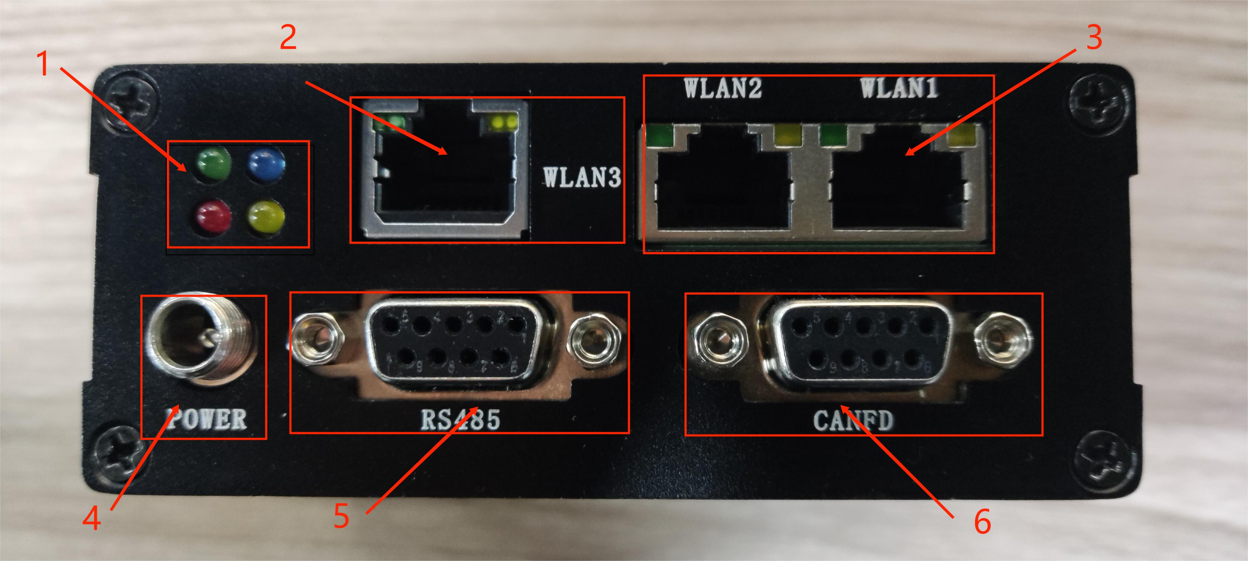
interface module description:
- module 1: indicator light, blue color indicates a successful connection;
- module 2: WLAN3,internal microcontroller network port, reserved;
- module 3: WLAN2,WLAN1,industrial protocol dual port, WLAN1 connects to the PLC and WLAN2 connects to the computer where the Boto software is located; ;
- module 4: power (DC,12V~24V);
- module 5: RS485 bus, communication with control cabinet;
- module 6: CANFD,internal microcontroller reservation;
Note: The hardware module supports Profinet, Ethernet/IP, and EtherCAT industrial protocols, which are selected for use according to the software, see [ICM Gateway Service Profile].
1.2.2 Hardware Wiring Diagram
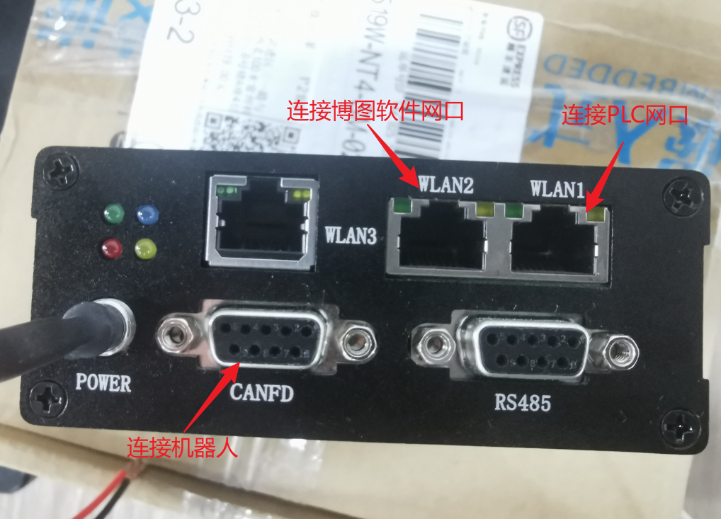
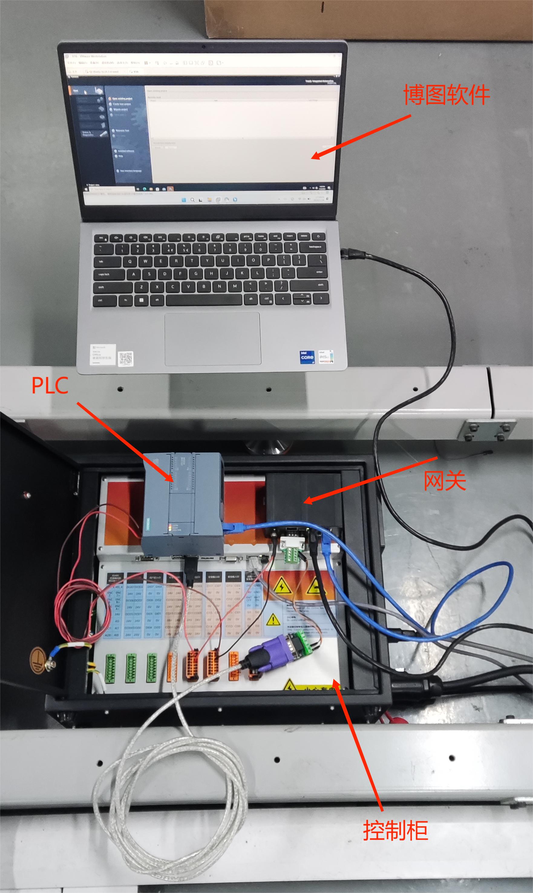
(1) power supply line (red positive and black negative), the figure directly from the robot arm control cabinet power supply.
(2) usb to 485 communication cable, field use need to use shielded wire, metal shell grounding; (3) Correct wiring, after power on the hardware gateway green light (as shown in the picture).
(3) Correct wiring, after power on, the green light of the hardware gateway (such as the green light status of the gateway in the above figure) is on; the gateway is successfully connected with the PLC and can communicate normally, the blue light of the hardware gateway is on.
2 Gateway and PLC Communication Configuration
The configuration here is based on the Profinet protocol and is similar for other protocols;
2.1 PLC New Profinet project
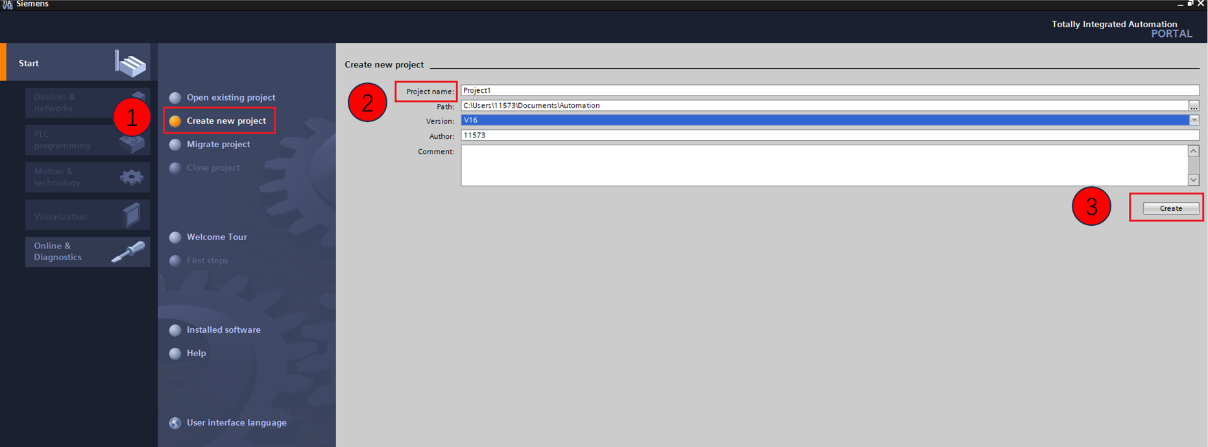
Double-click to open the Boto software, enter the main page, select [Start] -> [Create a new project], as shown in the figure below, and follow the step-by-step labeling operation.
2.2 Siemens model and version configuration
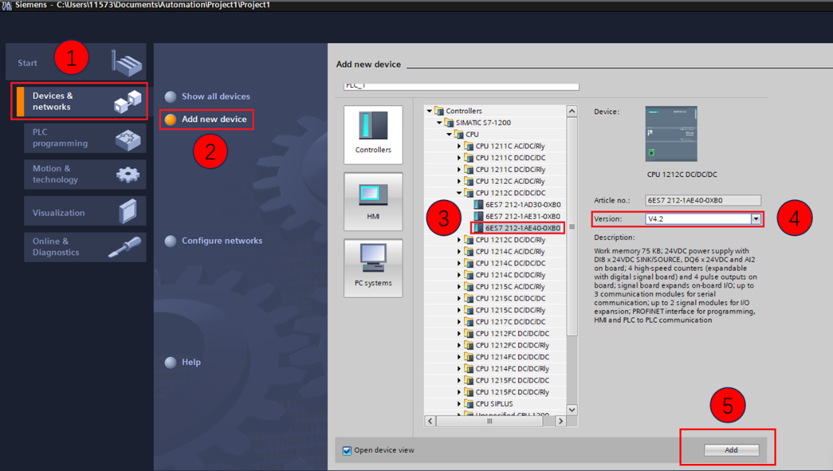
Double click [Add New Device] -> [Controller] /CPU/CPU 1214C DC/DC/DC 6ES7 214-1AG40-0XB0 under the newly created project and select it as shown below. Check the information and [Add].
2.3 PLC Settings
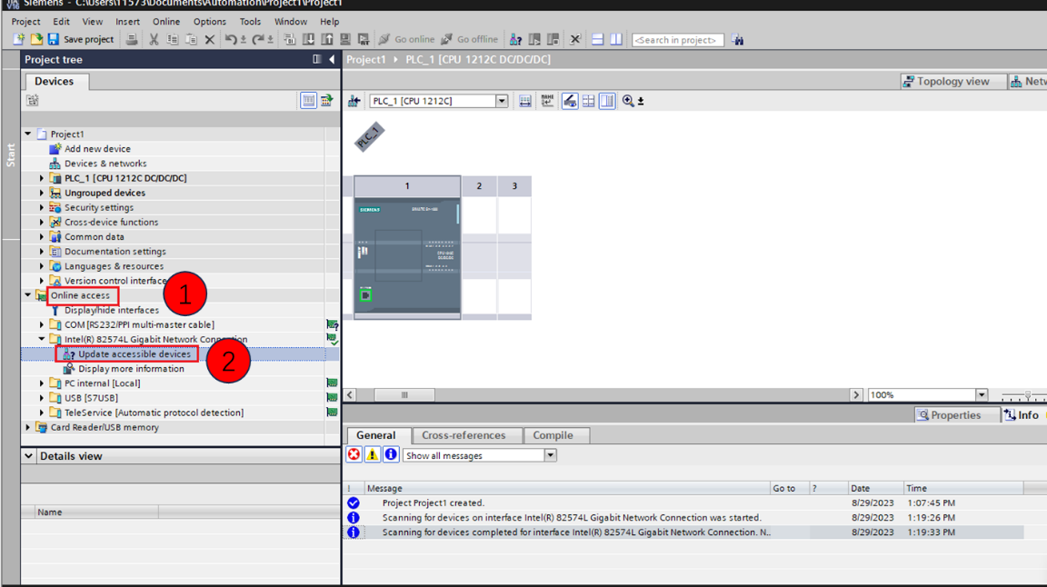
Search for Robotic Arm Device Station Open the project, [Online Access] -> [Computer NIC Name], double click [Update Accessible Devices] as shown below:
2.4 Gateway IP and Device Station Configuration
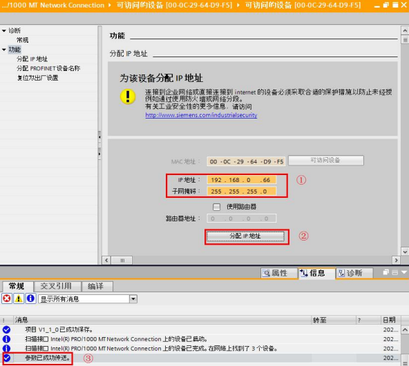
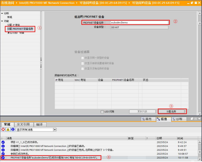
Double-click [Online and Diagnostics], and configure the IP address, device station name respectively as shown in the following operation steps.
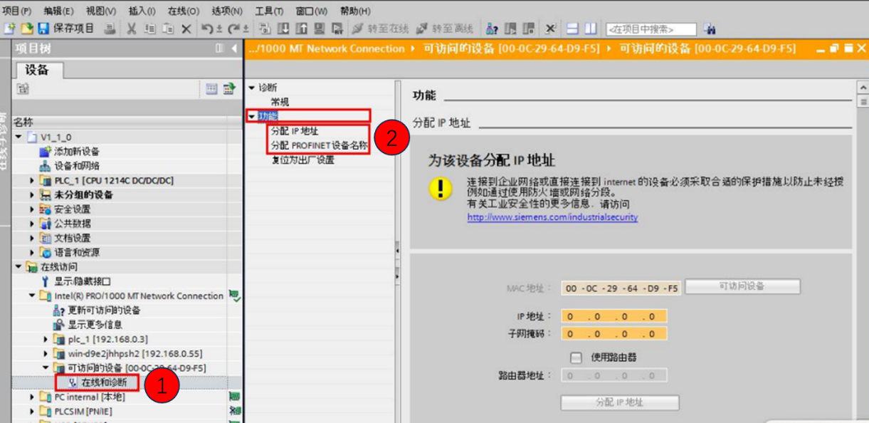
Note: If there is a default IP address and device station name displayed, it should have been set before, after checking the IP and name, skip this step (2.4) and continue to operate later.
Assigning a Gateway IP Address
Assign gateway device station name
2.5 PLC importing a gsd file
In the Boto software menu bar [Options] -> [Manage General Station Description File (GSD)], as shown in the following figure:
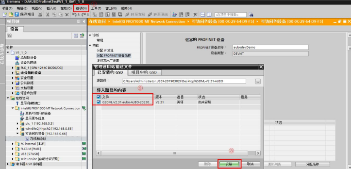
Note: The GSD file is provided by AUBO development, you can find the relevant engineers to get the newer version.
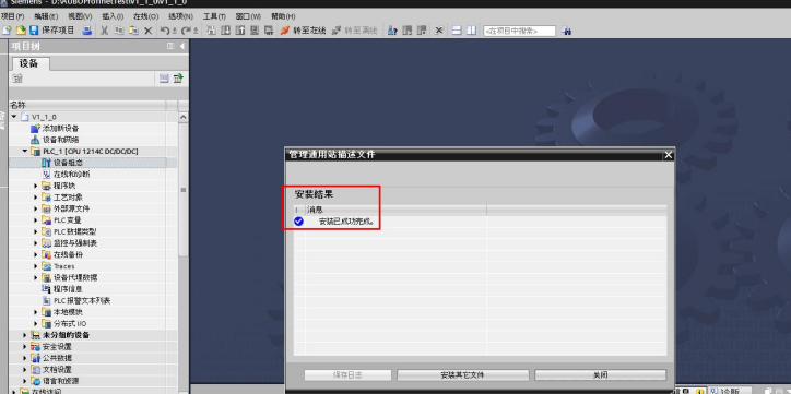
Successful installation is prompted as shown in the following figure, after successful installation [Close] can be, as follows:
2.6 PLC Configuration
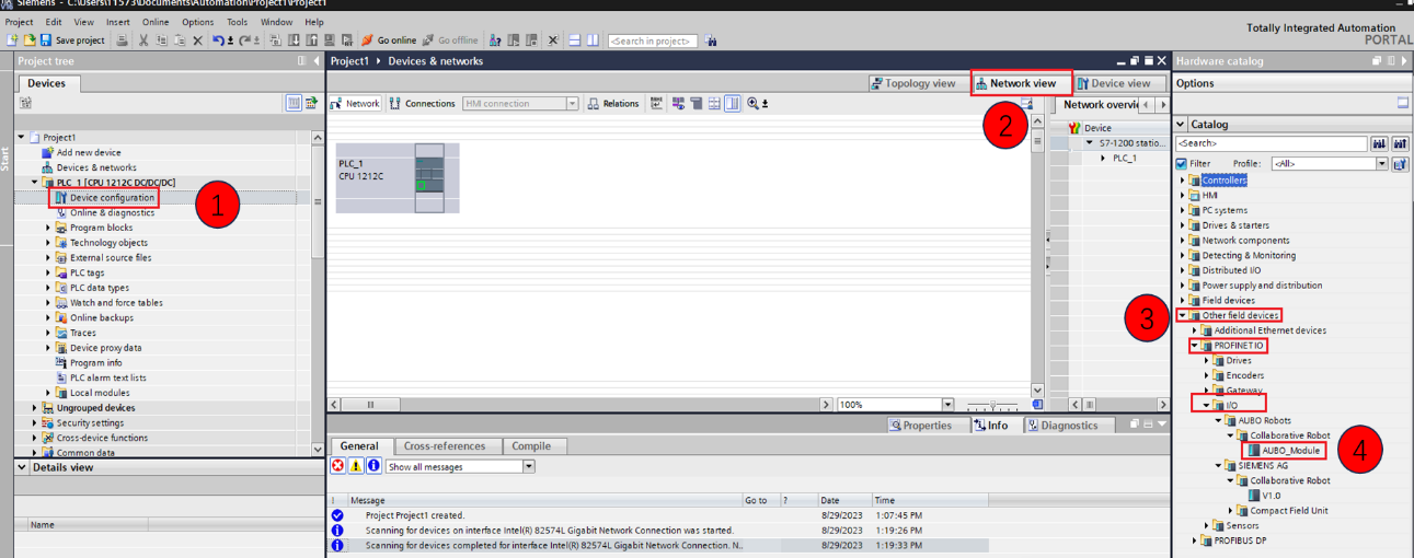
Double-click [Device Configuration] -> Click [Network View] -> [Other Field Devices] -> [IO] -> [AUBO Robot] -> Double-click [AUBO_Module] as shown below:
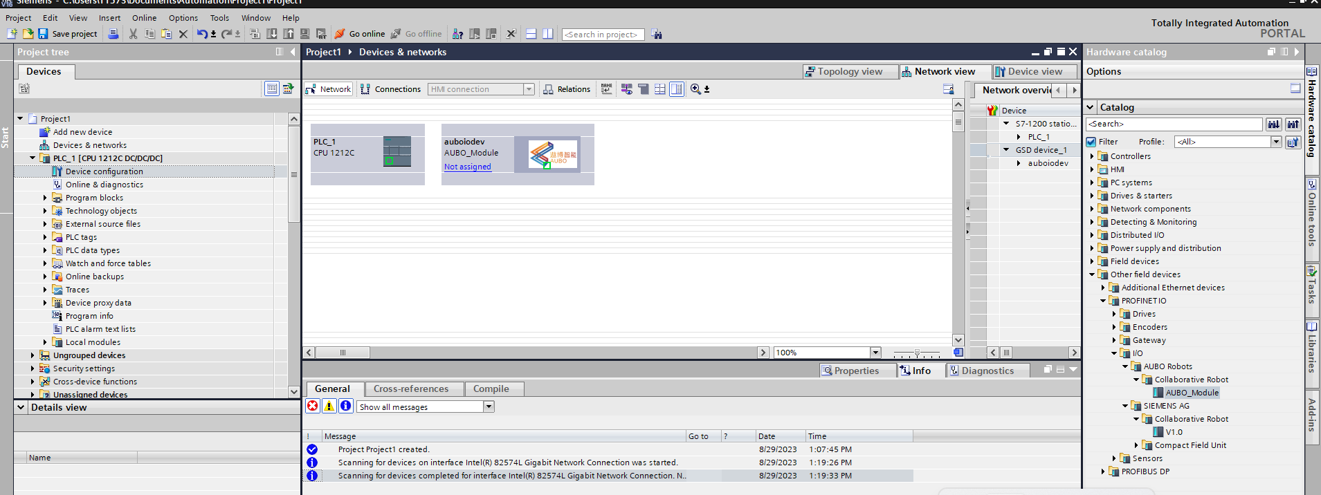
Successfully added as shown below:
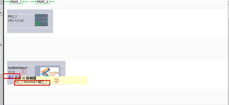
Click Unassigned and select ② as shown below:
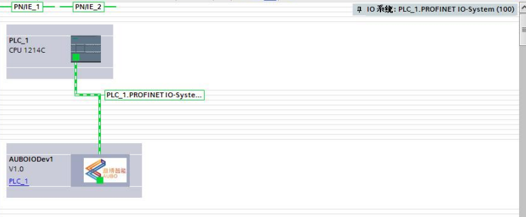
The successful configuration is shown below:
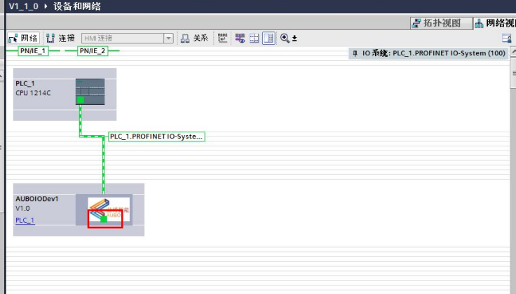
Communication settings:
Double-click on the Ethernet port in AUBOIODEV1, as labeled in the following figure:
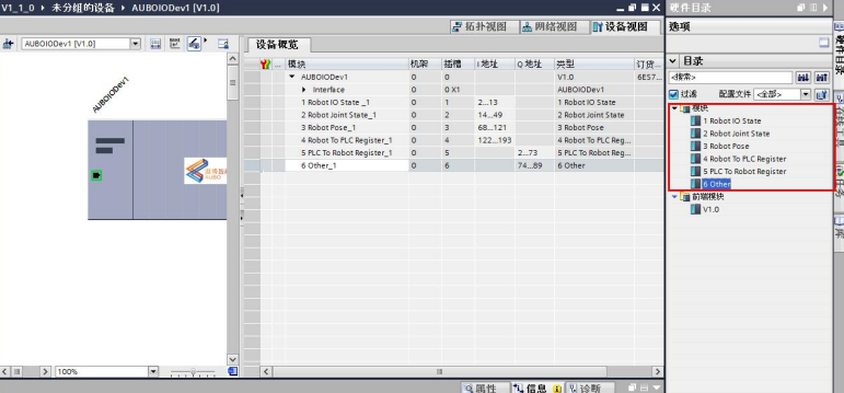
Slot Module Add:
Double-click each slot in [Module], and in [Module] on the right side of the interface, double-click 1-6 slots to add them to the device, as shown in the following figure:
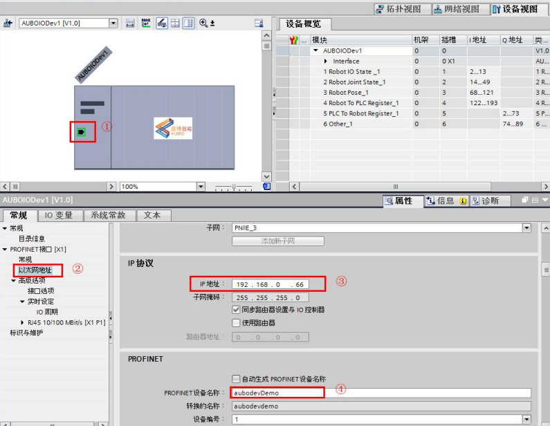
Configure the IP of AUBOIODev1 :
Double-click the Ethernet port, select [Ethernet Address], set the IP address of the gateway device station, and set the name of the device station, as shown in the following figure:
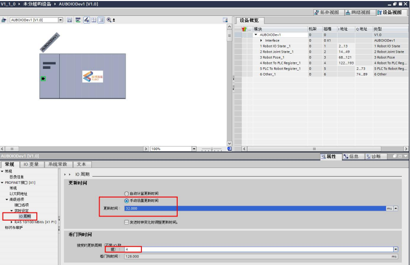
Recommended IO cycle settings:
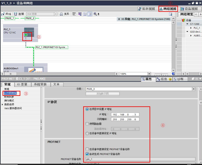
PLC IP configuration:
Click [Network View] -> click PLC [Ethernet] port, select [Ethernet Address], set the IP and device name of PLC, as shown below:
2.7 Save Project > Compile > Download > Load
All configurations are completed, save the project, operations ① to ⑤, compile -> download, search for devices, download; the steps shown in the following figure:
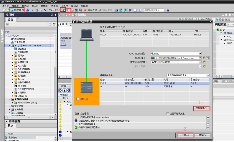
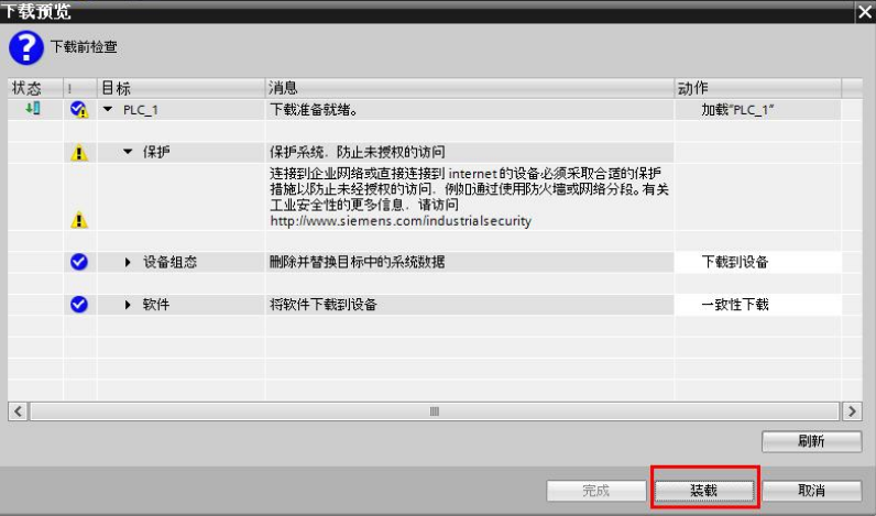
Note: If step ④ [Start Search] is grayed out, check that the AUBO robotic arm station name settings are consistent. Follow the prompts step by step until [Load] appears.
2.8 运Run and go online
Switch the PLC to Run mode, click [Go to Online], and perform the steps shown below:
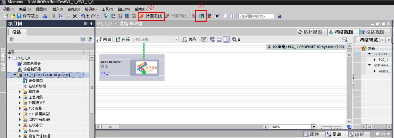
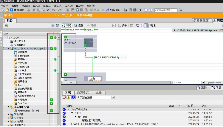
The PLC is successfully connected to the gateway device station, and the interface is all green connected, as shown in the following figure:
3 PLC and controller communication
3.1 function introduction
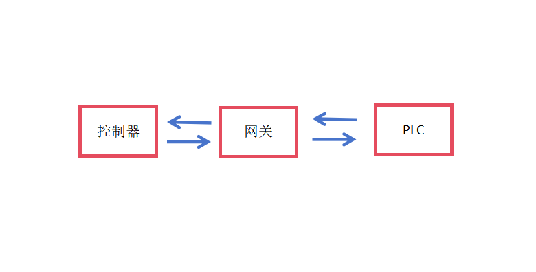
The hardware gateway acts as a transit device for the conversion between different protocols, connecting the Robot Controller via RS485 at one end and the PLC device at the other end, so that the PLC can read the robot IO status, position information, coil and hold registers and other data content, and at the same time, can realize the functions of the robot project such as start, pause, continue, stop, etc. through the control project. Currently, the gateway supports Profinet, Ethernet/IP, and EtherCAT protocols, and this test uses the Profinet protocol.
Communication Schematic:
3.2 ICM Usage
3.2.1 ICM Start-Stop
The gateway service ICM is used as a background process to exchange data with PLC, to use ICM, you need to import OEM package, please refer to [How to install OEM package], after installing and rebooting the device, it will restart ICM. How to install OEM package, ICM will be restarted after the installation is completed and the device is restarted, ICM realizes the self-start function, and it can also be manually pause, the command is as follows:
ICM Run Log View command:
tail -f /root/arcs_ws/log/icm/aubo_icm.logICM Communication Log View command:
tail -f /root/arcs_ws/log/icm/icm_register.logICM service startup command:
systemctl start aubo_icmICM service stop command:
systemctl stop aubo_icmICM service restart command:
systemctl restart aubo_icmICM Status View command:
systemctl status aubo_icm
When the gateway is running normally, use the command: systemctl status aubo_icm with the following output:

3.2.2 Log display
(1) ICM log files
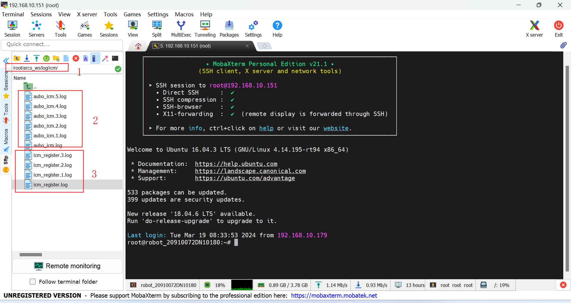
The ICM service program logging system is used to record information related to program execution, and is stored by default in the directory root/arcs_ws/log/icm/, the log includes two kinds:
aubo_icm.*.logstores the ICM runtime logs;icm_register.*.logstores the ICM communication log;
(2) ICM's operating log
root/arcs_ws/log/icm/aubo_icm.log the content is as follows:
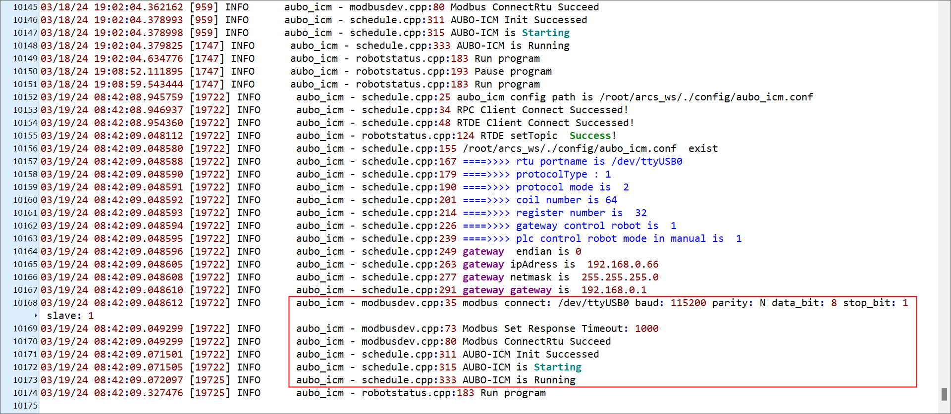
running Log explanation notes:
- When
ICM is Runningappears, it indicates that the ICM service process has been started successfully; - When
Run programappears, it indicates that the PLC control arm executes the "start program" action, and the logs of other actions are similar;
(3) Communication log for ICM
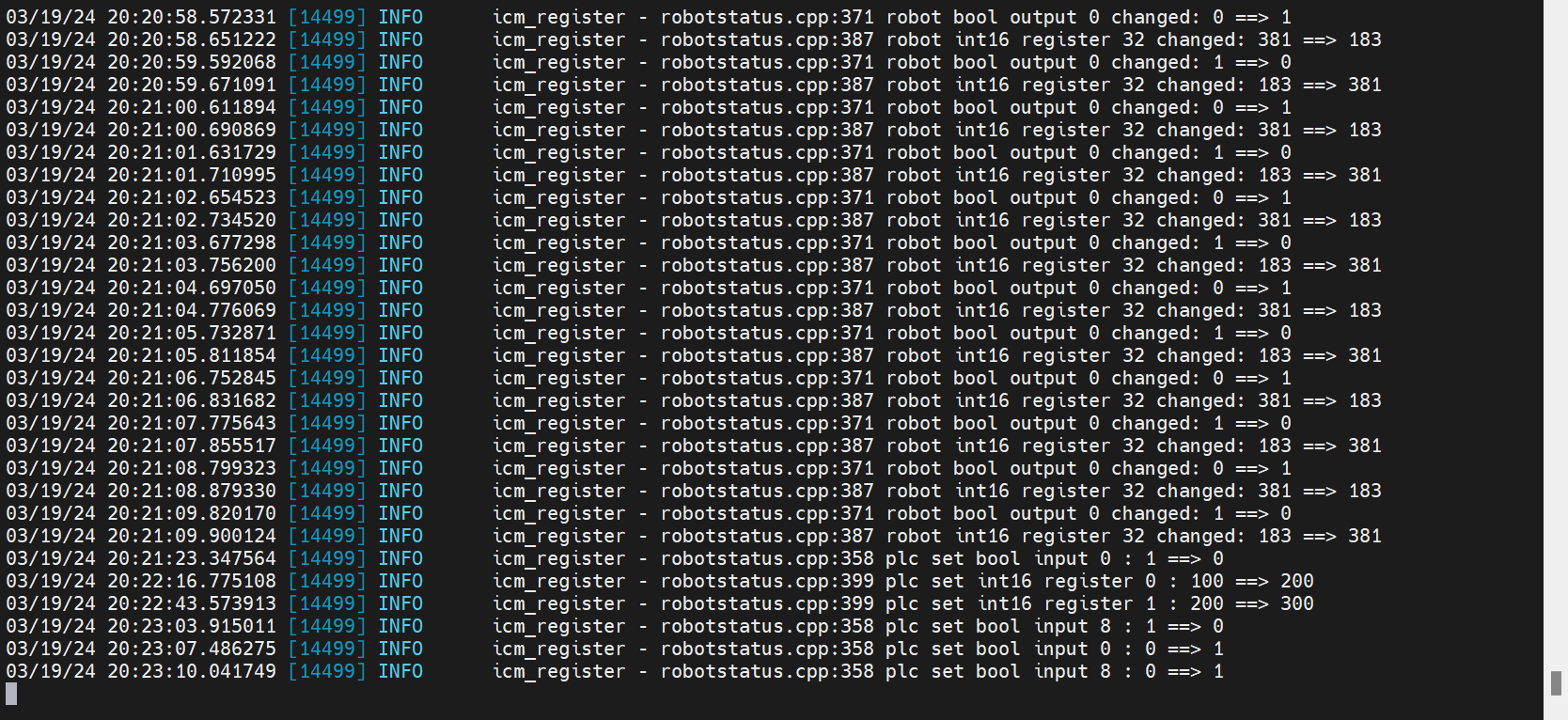
root/arcs_ws/log/icm/icm_register.log the content is as follows:
running Log explanation notes:
plc set bool input 0: 0 ==> 1means thatPLC to RobotusesgetBoolInput(0)to read the first bool quantity of the starting address of PLC slot_5, which has the original value of 0, and reads the value of 1;plc set int16 register 0: 100 ==> 200indicates thatPLC to RobotusesgetInt16Register(0)to read the first word(16Bit) quantity starting at the 9th byte of PLC slot_5, which has an original value of 100 and reads a value of 200;robot bool output 0 changed: 0 ==> 1Indicates thatRobot to PLCis usingsetBoolOutput(0,true)to set the first bool quantity (originally false) at the start address of PLC slot_4 to true;robot int 16 register 32 changed: 183 = = > 381means thatRobot to PLCusessetInt16Register(32,381)to write the first data (original value is 183) of PLC slot_4 holding register (the 9th byte of slot_4 is the starting address of holding register) into the value of 381;
Oscillator Log Display
The related operation of using PLC to control the project will display the log in the log interface of the demonstrator, which currently supports powering up, starting the robot, starting the project, pausing the project, continuing the project, stopping the project and so on, and the details of which need to be referred to the latest protocol; the logs are displayed as follows:
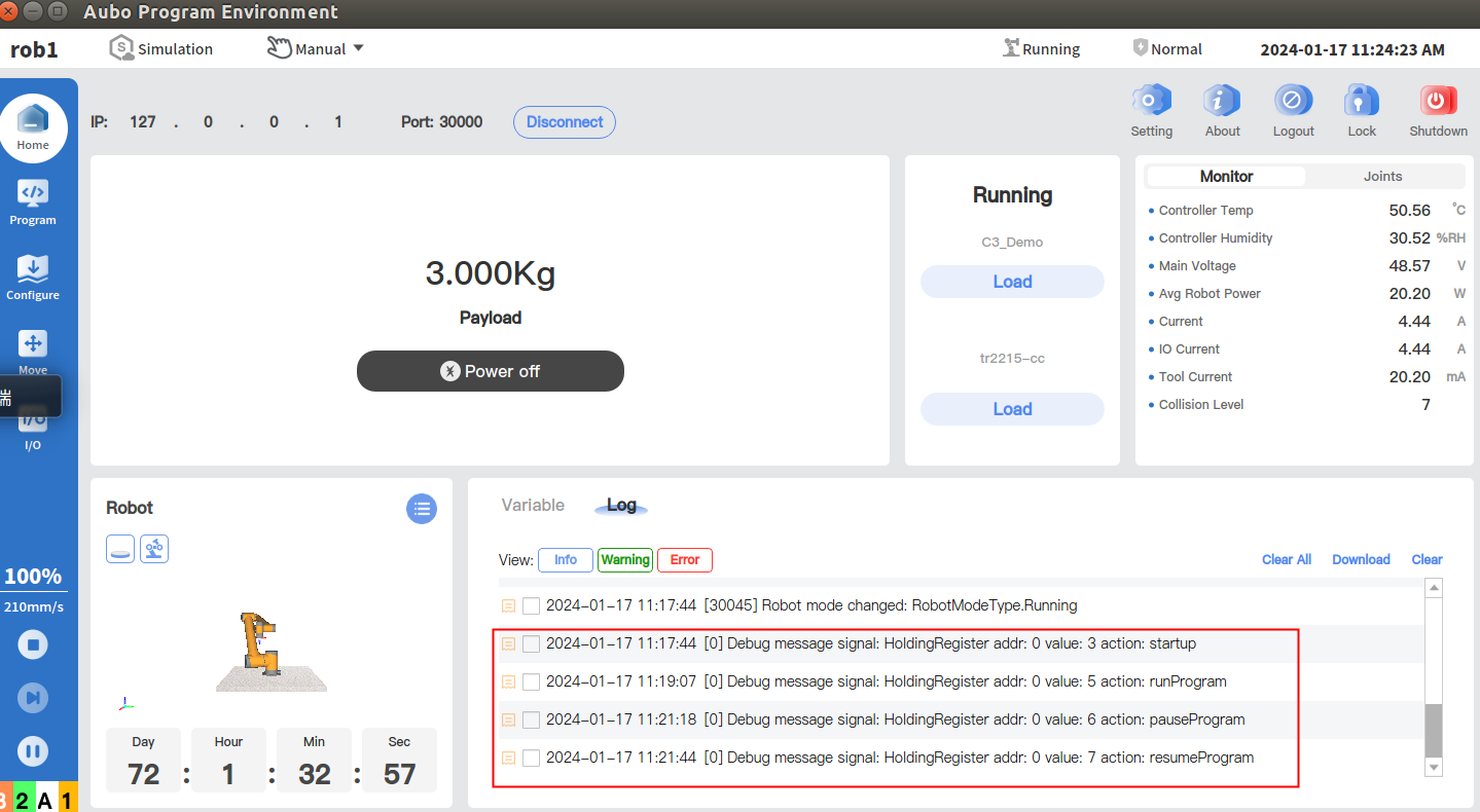
Log Explanation Notes:
For example: Debug message signal: HoldingRedister addr:0 value:3 action: startup
Indicates that the controller side received the signal value "3" transmitted from the PLC side in the save register at address 0, which triggered the power-up action of the controller side;
Note: When the PLC fails to read data, confirm by checking the log system.
3.3 PLC and Controller Communication Example
This communication uses the Profinet protocol, and the PLC communicates with the robot arm, including the following:
The robot arm is in the IO state (slot_1)
Robotic arm position (slot_2)
Robotic Arm Joint Current Voltage Temperature (slot_3)
Coil Holding Register (slot_4、slot_5)
control engineering (slot_6)
slot_1, slot_2, slot_3 can be read directly by PLC, slot_6 can be written directly by PLC, slot_4, slot_5 coil and hold registers are realized by the way of ARCS system script call, the specific use method is as follows;
Note: Protocols are updated, please contact your engineer for the latest protocols (Profinet, Ethernet/IP, EtherCAT );
solenoid
The first 8 bytes of slot_4 and slot_5 are used as coils (bool quantities), and the 9th byte is used as a holding register.
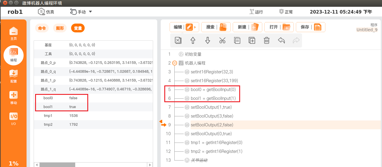
(1) PLC to Robotbool0 = getBoolInput(0), reads the first bool quantity at the PLC slot_5 start address and saves it in the variable boll0
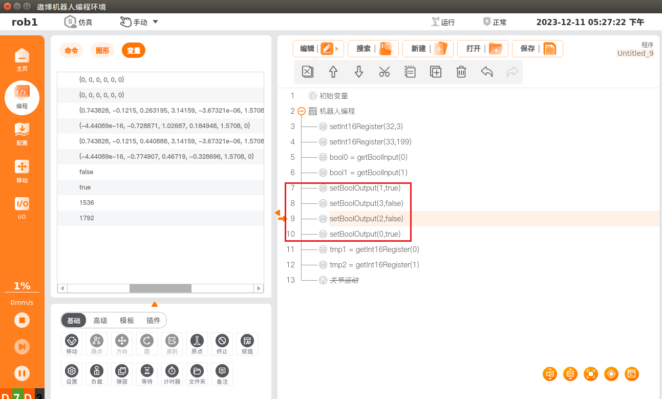
(2) Robot to PLCsetBoolOutput(0,true), sets the first bool quantity at the PLC slot_4 start address to true.
Hold register
(1) PLC to Robottmp1 = getInt16Register(0), the robot reads the first word(16Bit) quantity starting at byte 9 of PLC slot_5 and saves it in the variable tmp1.
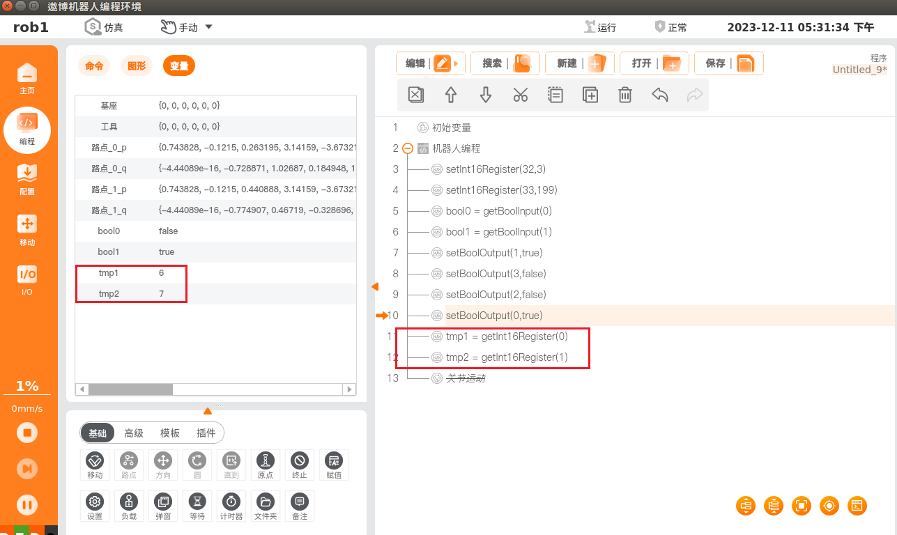
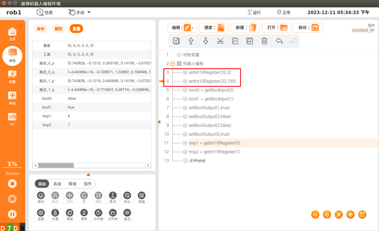
(2) Robot to PLCsetInt16Register(32,3), writes the first data of PLC slot_4 holding register (the 9th byte of slot_4 is used as the starting address of holding register) to value 3, where the starting address of setInt16Register is 32.
PLC-side read/write data
Read and write operations to addresses in the PLC are performed in the Boto software according to the Profinet address protocol, as shown in the example below:
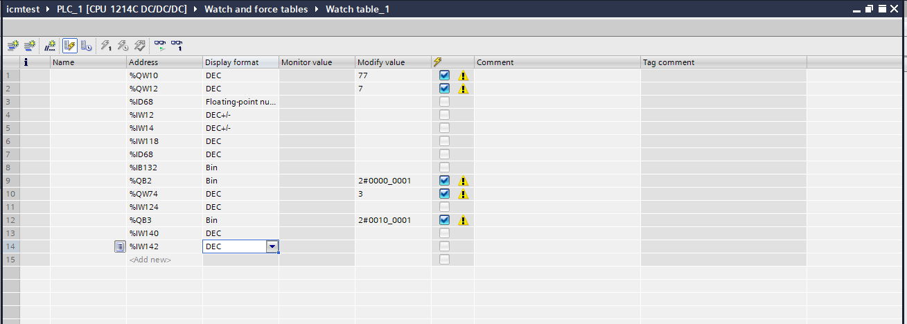
Note: The monitored addresses in this figure are filled in arbitrarily according to the protocol address table during the test, and are changed according to the actual situation in the actual application.
4 Common problems
4.1 communication failure
(1) Check whether the hardware wiring is correct, whether the network cable and serial cable are loose, and whether the power cable of gateway and PLC is loose;
(2) Check whether the gateway and PLC can be pinged, after the gateway and PLC are successfully connected, the blue light will be on, and no red light will be on the PLC;
(3) Check the running log of ICM, when the following log appears, it means that the gateway service is running normally, otherwise, there is a problem;
(4) The configuration file automatically generated by ICM can not be used directly, and needs to be configured according to the actual situation, the configuration reference is as follows:

4.2 Communication successful, data read error
(1) The data changes, but the result is not correct, you need to modify the littleEndian item in the configuration file to see if the wrong size end is selected;
(2) The data does not change, but the ICM service process is executing, you need to restart the ARCS software and observe the last line of the log, the appearance of AUBO-ICM is Running means that the service has been started and the data transmission with the gateway is in progress;
