
29 ARCS Modbus User Guide
1. Modbus Protocol Introduction
Modbus is a serial communication protocol originally designed by Modicon (now Schneider Electric) in 1979 for automation equipment using programmable logic controllers (PLCs). Modbus has become the de facto standard for industrial communication protocols. The Modbus protocol includes Modbus RTU and Modbus TCP.
Modbus RTU (Remote Terminal Unit) is a binary communication protocol based on serial lines such as RS-485, RS-422, and RS-232. In Modbus RTU, data is transmitted in binary form, and each byte is represented by two hexadecimal characters. Modbus RTU is mainly used in industrial and system automation applications where the communication distance between devices is relatively long.
Modbus TCP (Transmission Control Protocol) is an Ethernet-based communication protocol. Modbus TCP uses TCP/IP for communication and therefore can use existing Ethernet infrastructure. Compared with Modbus RTU, Modbus TCP supports more device connections and provides a higher communication speed.
Main differences between Modbus RTU and Modbus TCP:
Modbus RTU uses serial communication, such as an RS-485 interface, and its transmission rate is limited by the performance of the serial interface.
Modbus TCP uses the TCP/IP protocol stack to transmit data over a network and supports a higher transmission rate.
2. Modbus Master
2.1 Master Introduction
In a Modbus communication network, the master station is the device that initiates communication. It controls and coordinates communication with slave stations. The master actively requests data from slave stations or sends commands to them to manage the network and exchange data.
2.2 Master Applications
When a robot acts as the master during welding, handling, assembly, or other operations, it requests data from or sends commands to a PLC slave station according to its task flow and operating state.
- Example: During automotive component assembly, the robot can obtain component position information from the PLC so that it can accurately pick up and install the components.
A robot acting as the master generally has a high level of intelligence. It can analyze and process the received data and make appropriate decisions.
- Example: Based on equipment status information provided by the PLC on the production line, the robot can adjust its operating pace and motion sequence to coordinate with other equipment.
2.3 Modbus Entry
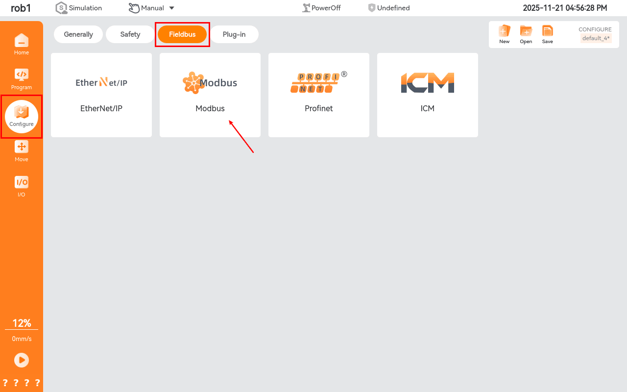
Open the home page of AUBO STUDIO, then click Configuration > Fieldbus > Modbus in the left navigation bar to open the Modbus Client I/O Settings page.
2.4 Master Modbus TCP
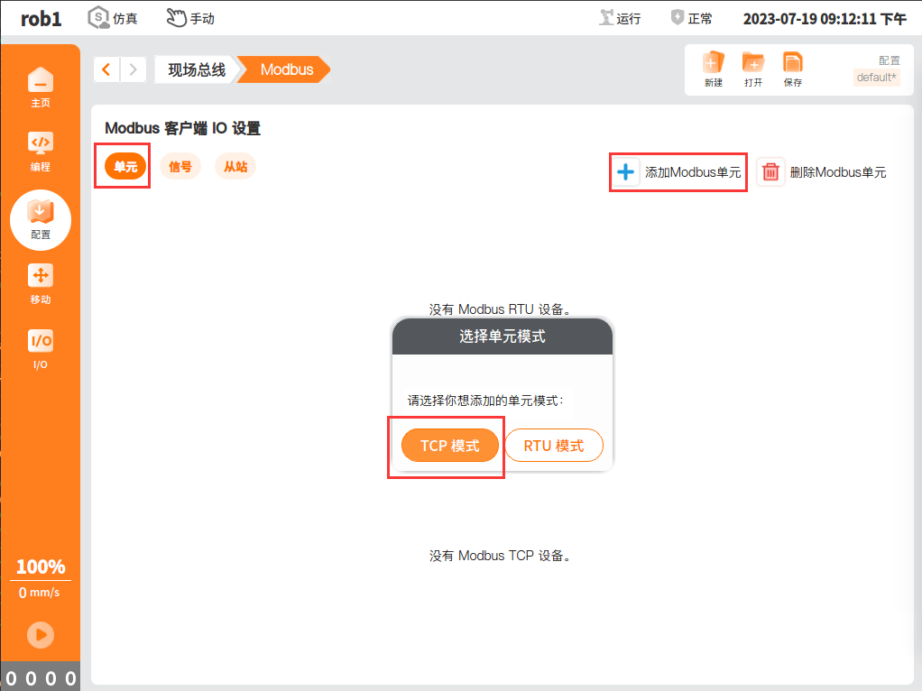
Unit page: On the Modbus Client I/O Settings page, click Unit > Add Modbus Unit > TCP Mode.
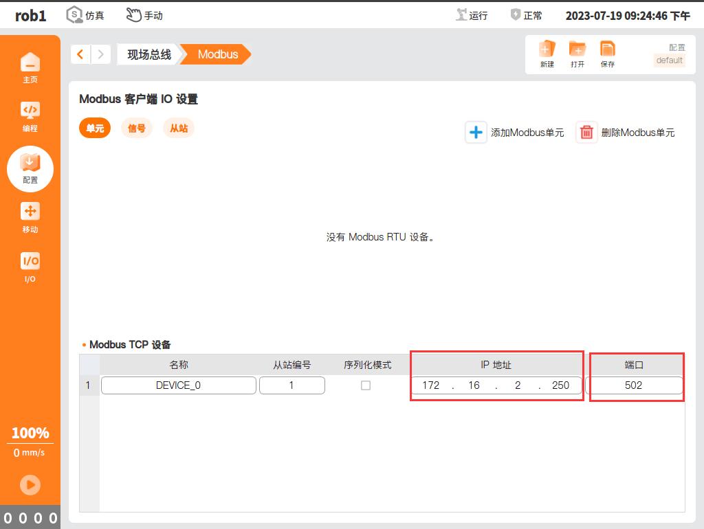
Modbus TCP device: The device uses a TCP/IP connection and does not require checksum calculation. You can configure Device, Name, Slave Number, IP Address, Port, and Operation. After configuring the IP address, click Test. A successful test indicates that the target device can communicate with the robot. If the test fails, check whether the robot and target device are on the same network segment, whether the firewall is disabled, and whether other network settings are correct.
Note
Make sure that the TCP device and the target device are on the same network segment.
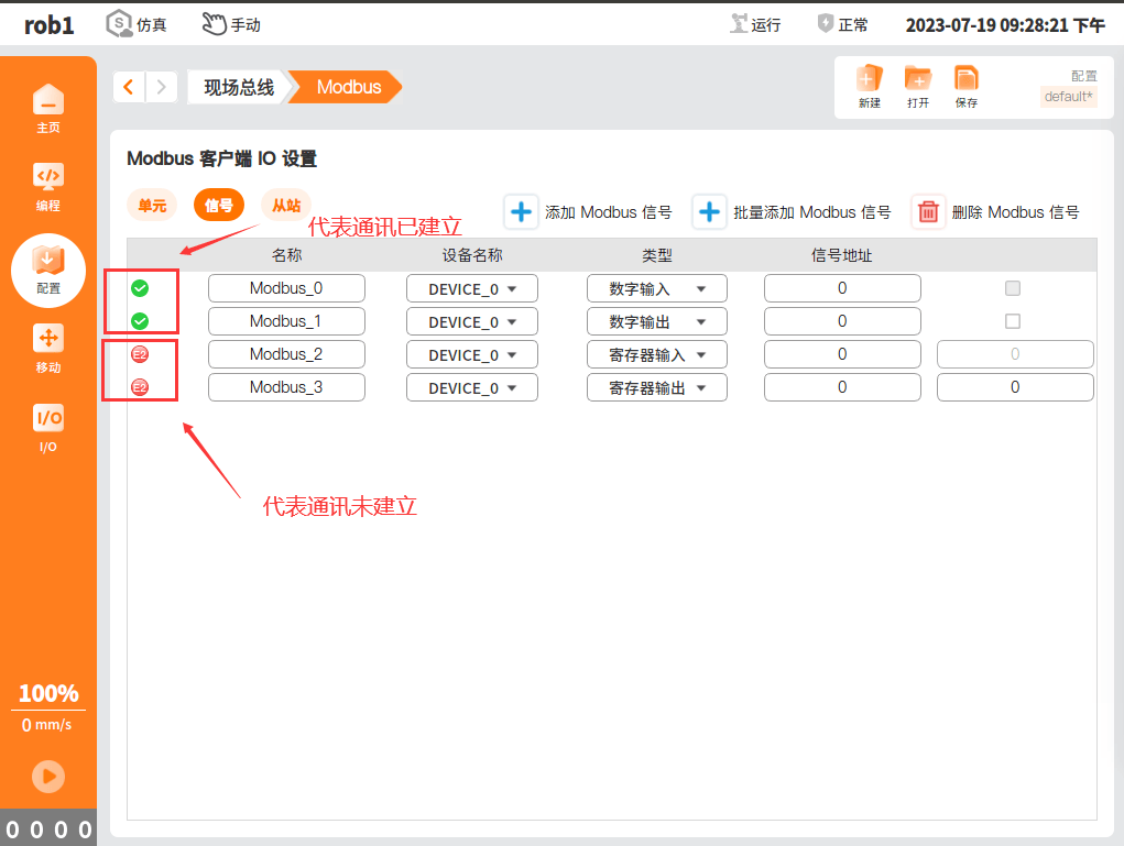
Signal page: On the Modbus Client I/O Settings page, click Signal > Add Modbus Signal.
- COIL STATUS: Reads and controls the switching status of a remote device, and is commonly used to control switching devices such as relays.
- INPUT STATUS: Reads the input status of a remote device, and is commonly used to read the status of input devices such as sensors.
- HOLDING REGISTER: Stores and reads data from a remote device, and is commonly used to store control parameters and device status.
- INPUT REGISTER: Stores input data from a remote device, and is commonly used to store data from sensors and other input devices.
- Green indicates normal communication. Gray and red indicate no communication. The red response codes are as follows:
- E1: Illegal function (0x01). The function code received in the query is not an operation allowed by the server (or slave).
- E2: Illegal data address (0x02). The data address received in the query is not an address allowed by the server (or slave). Check whether the configured signal address matches the settings of the remote MODBUS server.
- E3: Illegal data value (0x03). The data field contains a value that is not allowed by the server (or slave). Check whether the signal value is valid for the specified address on the remote MODBUS server.
- E4: Slave device failure (0x04). An unrecoverable error occurred while the server (or slave) attempted to execute the requested operation. Check whether the device or wiring is damaged, and try restarting the device.
- E5: Acknowledge (0x05). This code is used with a programming command sent to the remote MODBUS unit.
- E6: Slave device busy (0x06). This code is used with a programming command sent to the remote MODBUS unit and indicates that the device (server) cannot respond at this time. Wait or try reconnecting. Also check whether the robot IP address conflicts with the IP address of another device on the same local network.
2.5 Master Modbus RTU
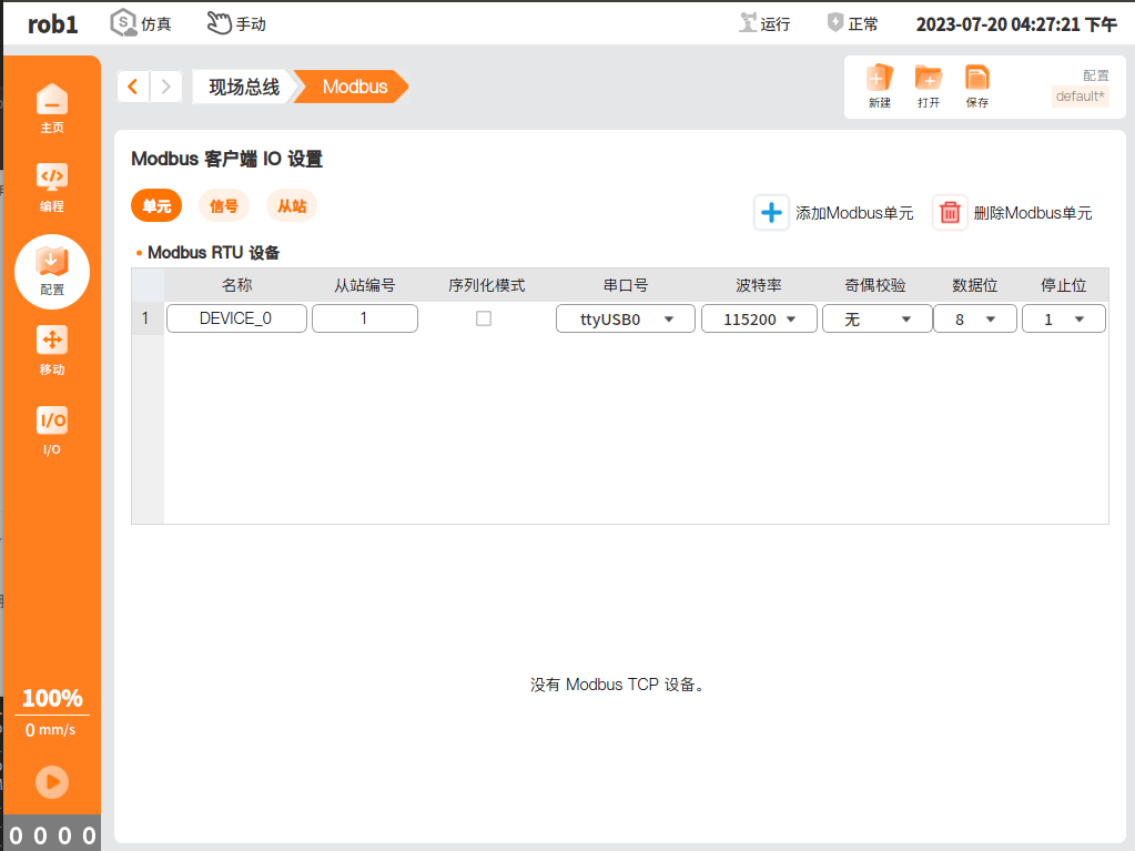
Unit page: On the Modbus Client I/O Settings page, click Unit > Add Modbus Unit > RTU Mode.

Modbus RTU device: Configure Device Name, Slave Number, Serial Port, Baud Rate, Parity, Data Bits, and Stop Bits.
Note: Modbus RTU uses serial communication, and its transmission rate is limited by the performance of the RS-485 serial interface. If communication is unstable and the signal status flashes, reduce the baud rate. If there is no communication, check whether the selected serial port is correct. You can use a Modbus serial port assistant for troubleshooting. For details, see:
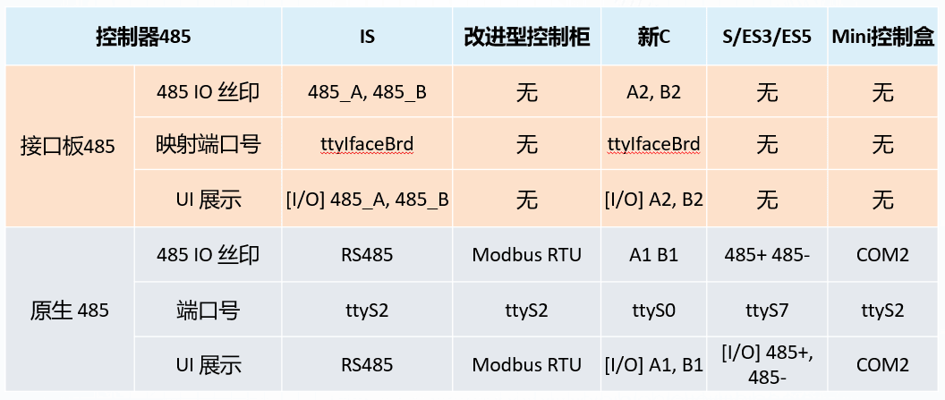
Modbus RTU communication depends on the RS-485 serial communication of the controller or robot end. Refer to the following information when selecting the Modbus serial port:
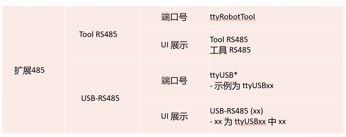
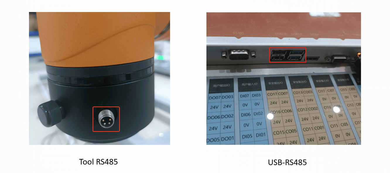
Configure the RS-485 serial port number. The controller RS-485 ports include the end-effector RS485 port and USB485.
2.6 Using Modbus Signals as I/O in Configuration
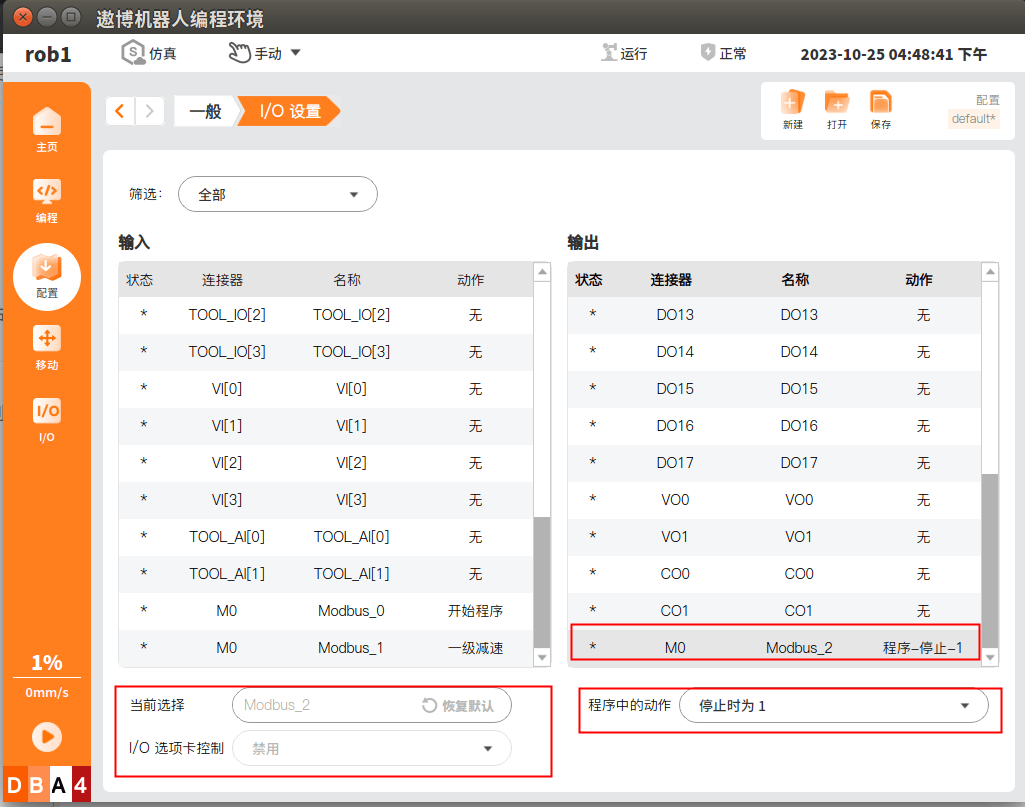
On the Configuration page, click General > I/O Settings to configure I/O input actions. Except for drag teaching, the other signals must be triggered in linked mode to execute the signal action. You can also use the OEM customization function to make the signals take effect in manual mode or automatic mode.
Before configuring this function, click Fieldbus > Modbus > Signal on the Configuration page and add a Modbus signal whose type is Register Input or Digital Input.
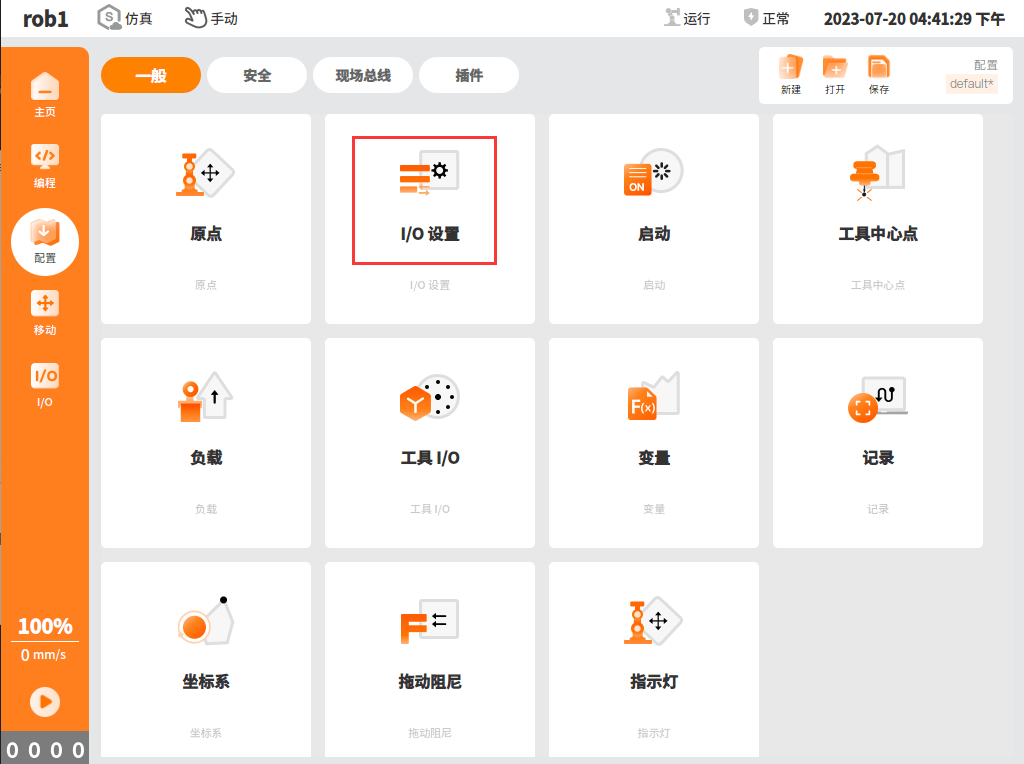
Configure the input action for the corresponding Modbus signal.
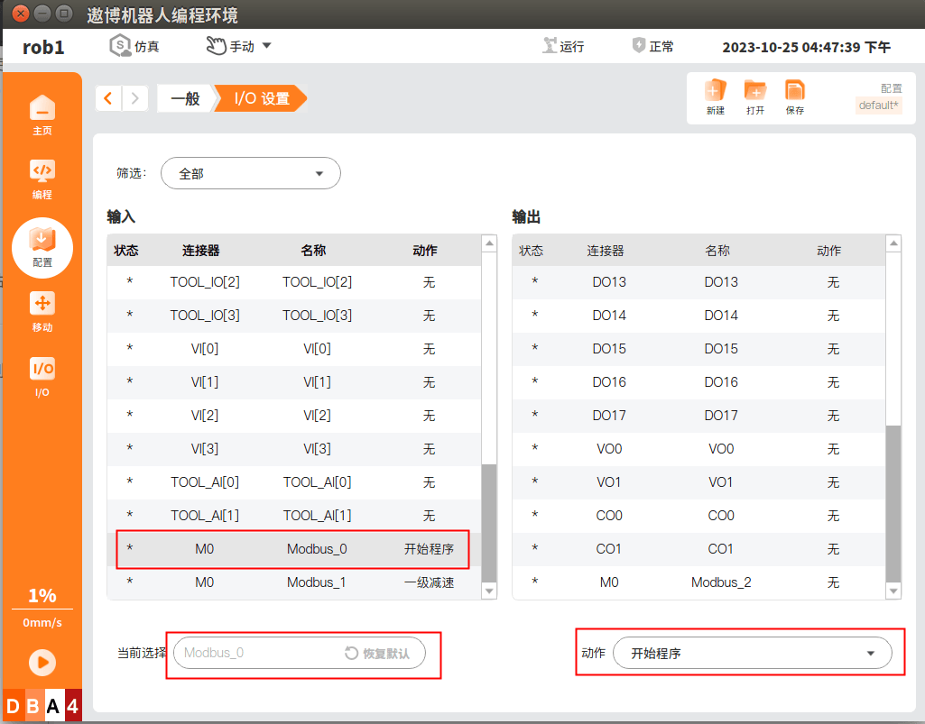
Configure the output action for the corresponding Modbus signal.
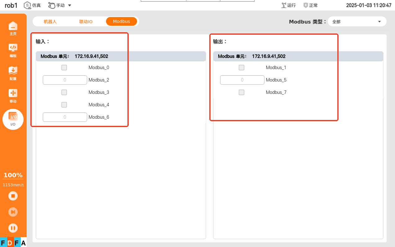
Click I/O > Modbus in the left navigation bar to view changes to signal registers and digital signals.
2.7 Using Modbus Signals in a Program
Set node: Set the Modbus signal's Digital Output and Register Output, as well as the single-pulse parameters of digital signals.
Tip
In most cases, use a Wait for Signal node for verification. Make sure that the signal is set successfully before the program continues with the subsequent process.
Wait node: Uses a Modbus signal as the condition. The program continues only after the signal meets the condition. This node is commonly used with the Set node.
Assignment node: Assigns the Modbus signal value to a variable for use in subsequent processes.
If node: Uses a Modbus signal as the condition. When the signal meets the requirement, the program enters the conditional flow.
Loop node: Uses a Modbus signal as the loop trigger. When the signal meets the condition, the program enters the loop flow.
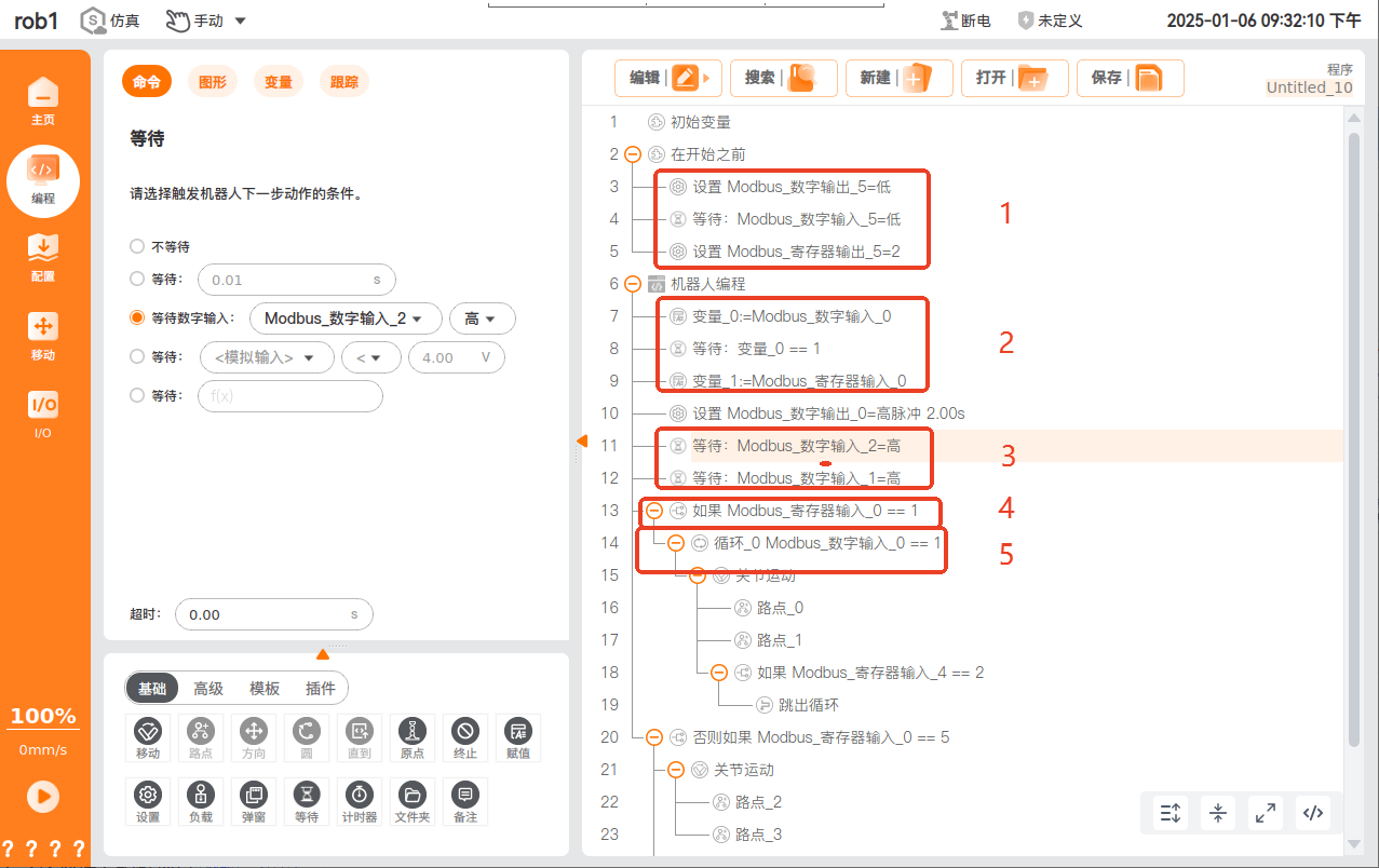
Click I/O > Modbus in the left navigation bar to view changes to signal registers and digital signals.
3. Modbus Slave
3.1 Slave Introduction
The main function of a Modbus slave is to respond to requests from the master and perform the corresponding operations. In practical applications, it can connect to and control various devices on a production line to exchange information and transmit control commands between devices.
3.2 Applications of the ARCS Slave
Respond to requests from the master and send the robot status information to the master in real time.
Respond to requests from the master and send controller information to the master.
Provide data during testing and debugging:
- Transmit changes in the robot I/O signals to the master in real time.
- Transmit custom signals from the master to the robot in real time.
Note
Using an ARCS master to connect to a slave may cause signal delays. Use this method only during debugging; do not use it in a program. To read and write slave registers in a program, refer to the general register read/write example in Section 3.6.
3.3 Location for Updating the Slave Address Table
The Modbus slave address table is updated in Dingpan - Team Files > ARCS > External Files > Modbus Slave. If you are a customer, contact the company's technical service personnel to obtain it. Technical service personnel can obtain it directly.
Download: Modbus slave address table_v1.14.xlsx
Correspondence between Modbus slave versions and ARCS versions:
| Modbus Version | ARCS Version | Modification Date | Changes |
|---|---|---|---|
| 1.0.4 | 0.29.2-beta.10 | 2024-08-19 | 1. Added control project. 2. Added project running status. |
| 1.0.7 | 0.31.0-beta.3 0.32.0-alpha.23 | 2024-12-26 | Updated robot series and robot submodels. |
| 1.0.8 | 0.29.4-rc.6 0.31.0-beta.5 0.32.0-alpha.32 | 2025-01-09 | Added Modbus slave output operation mode and heartbeat. |
| 1.0.9 | 0.29.5-rc.10 0.31.0-rc.12 0.32.0-alpha.73 | 2025-03-04 | Added read/write support for the project running speed percentage. |
| 1.0.11 | 0.29.5-rc.21 0.31.0-rc.26 0.31.1-beta.7 0.32.0-alpha.117 | 2025-04-25 | Added Modbus slave release of protective stop. |
| 1.0.12 | 0.29.5-rc.22 0.29.6-rc.1 0.31.0-rc.28 0.32.0-alpha.136 | 2025-05-12 | Added Modbus slave clearing of error pop-ups, including releasing protective stop and resetting the interface board. |
| 1.0.13 | 0.31.1-beta.9 0.32.0-alpha.131 | 2025-05-15 | Added Boolean registers. |
| 1.14 | 0.31.1-beta.10 0.32.0-alpha.139 | 2025-05-21 | Added project switching. |
| 1.14 | 0.31.1-beta.10 0.32.0-alpha.140 | 2025-05-22 | 1. Added support for outputting linked mode in the operation mode. 2. Added output of the Modbus version number. |
3.4 Slave Modbus TCP
On the Modbus Client I/O Settings page, click Slave and turn on the Modbus TCP switch.
After the slave is enabled, a master device such as a PLC or Modscan can connect to it. Refer to the Modbus slave protocol definition for the slave address.
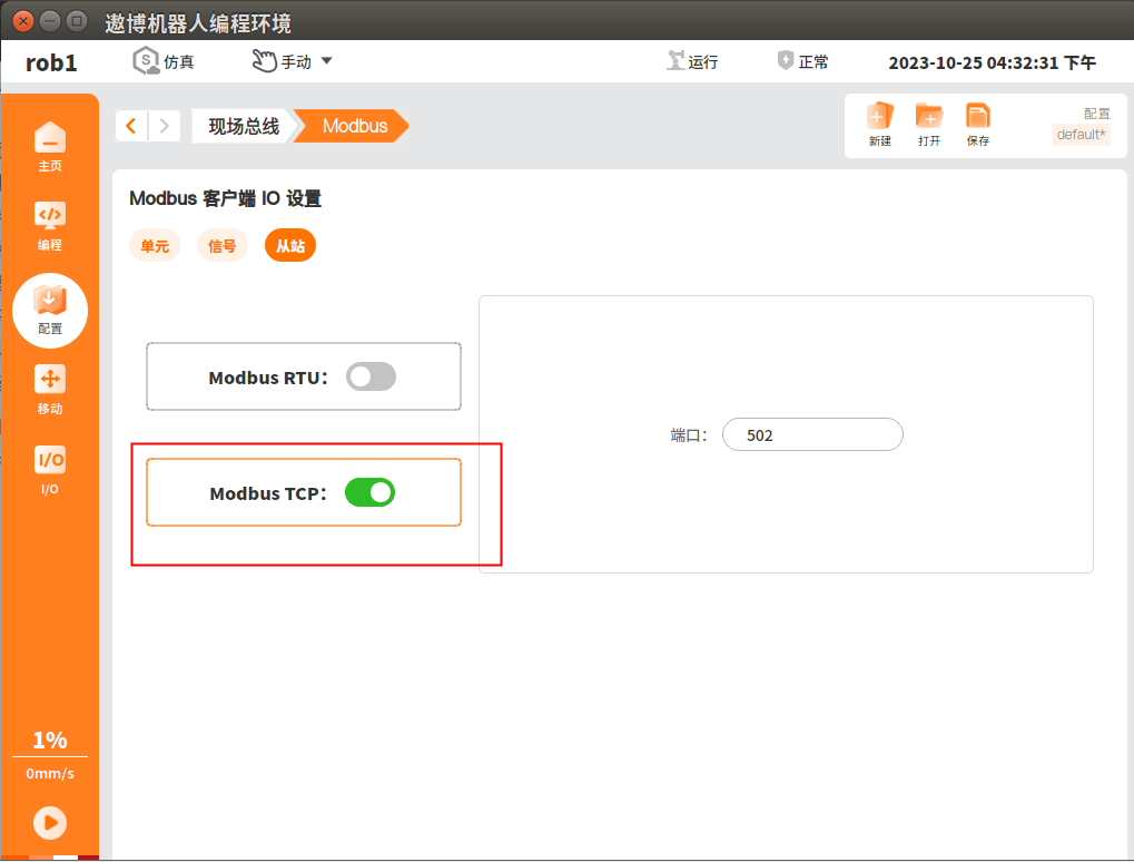
3.5 Slave Modbus RTU
On the Modbus Client I/O Settings page, click Slave and turn on the Modbus RTU switch.
Note
- Configure the serial port parameters before enabling the Modbus RTU slave.
- After the slave is enabled, its serial port parameters cannot be modified. Turn it off before modifying the parameters.
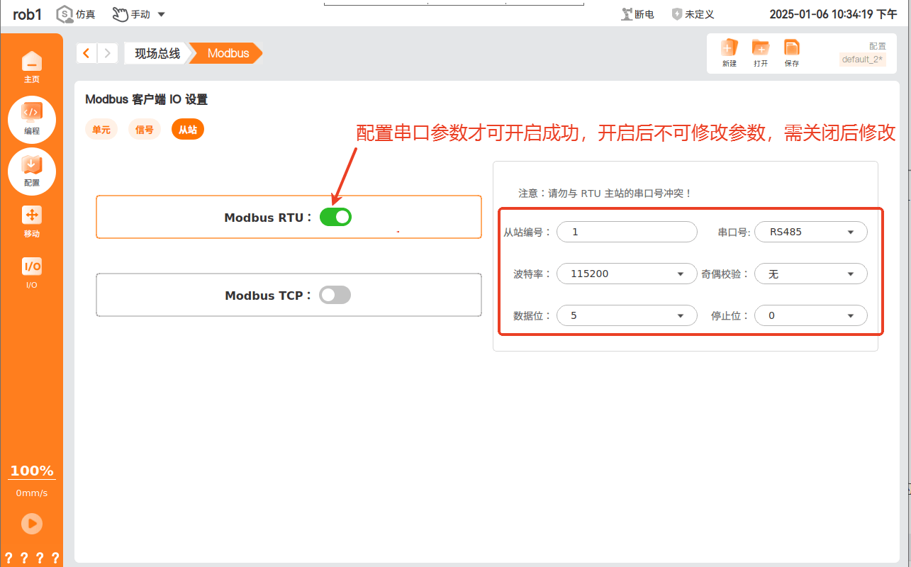
Modbus RTU communication depends on the RS-485 serial communication of the controller or robot end. Refer to the following information for the serial port parameters of different devices:
Note: Modbus RTU uses serial communication, and its transmission rate is limited by the performance of the RS-485 serial interface. If communication is unstable and the signal status flashes, reduce the baud rate. If there is no communication, check whether the selected serial port is correct. You can use a Modbus serial port assistant for troubleshooting. For details, see:
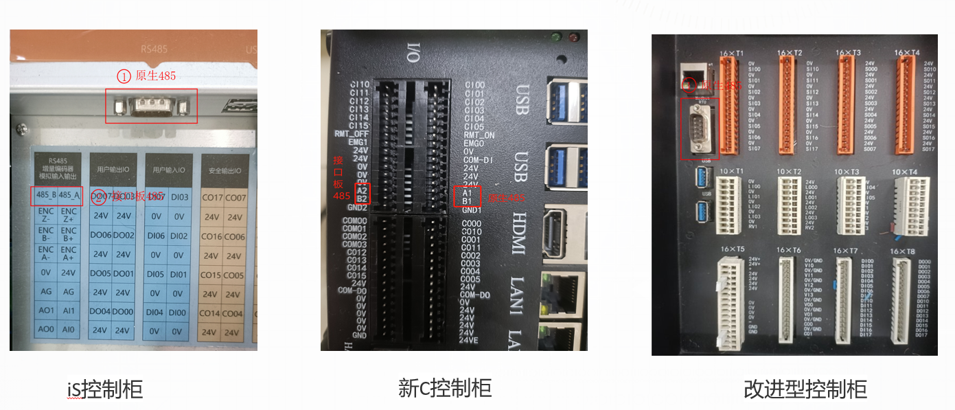
Configure the RS-485 serial port number. The controller RS-485 ports include the end-effector RS485 port and USB485.
3.6 Application Example: Reading and Writing Modbus Slave General Registers
3.6.1 Introduction to Modbus Slave General Registers
To allow users to use custom signals for communication between a PLC (master) and the controller, the Modbus slave provides dedicated readable and writable general registers. The addresses of the general registers are 300 to 525.
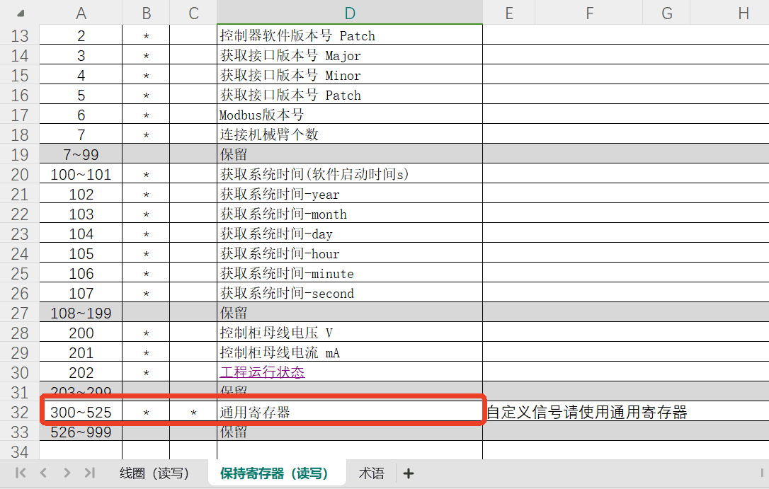
There are two typical general-register read/write methods:
- Use SDK interfaces to read and write the general register at the specified address.
- Use a project (Lua) script to read and write the general register at the specified address.
3.6.2 Reading and Writing General Registers Through Modbus TCP
Test environment:
The test uses Modbus TCP communication and Modbus Poll to simulate communication between a PLC master and the Modbus TCP slave. The relevant address signal settings in Modbus Poll are shown below:
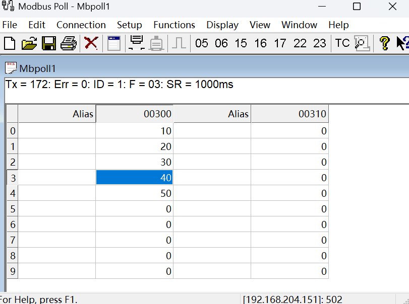
3.6.2.1 Reading and Writing General Registers Through the SDK
Reading a general register:
Core steps for reading a Modbus signal through the SDK:
- Call
modbusAddSignalto add a signal at the specified address. - Call
modbusGetSignalStatusto obtain the signal value at the specified address. - Call
modbusDeleteSignalto delete the signal.
- Call
Example: Use the SDK to read the general registers at addresses 300, 301, and 303 in the Modbus slave. The code is as follows:
c++// Read general registers void exampleModbusSlaveRead(RpcClientPtr impl) { // Create a holding-register signal at the specified slave address impl->getRegisterControl()->modbusAddSignal( MODBUS_SLAVE_IP, 1, 300, 0x03, "READ_HOLDING_REGISTER_300", true); impl->getRegisterControl()->modbusSetSignalUpdateFrequency( "READ_HOLDING_REGISTER_300", 10); impl->getRegisterControl()->modbusAddSignal( MODBUS_SLAVE_IP, 1, 301, 0x03, "READ_HOLDING_REGISTER_301", true); impl->getRegisterControl()->modbusSetSignalUpdateFrequency( "READ_HOLDING_REGISTER_301", 10); impl->getRegisterControl()->modbusAddSignal( MODBUS_SLAVE_IP, 1, 303, 0x03, "READ_HOLDING_REGISTER_303", true); impl->getRegisterControl()->modbusSetSignalUpdateFrequency( "READ_HOLDING_REGISTER_303", 10); std::this_thread::sleep_for(std::chrono::seconds(1)); int i = 30; while (i--) { // Get the value of the holding-register signal at the specified address auto ret0 = impl->getRegisterControl()->modbusGetSignalStatus( "READ_HOLDING_REGISTER_300"); std::cout << "READ_HOLDING_REGISTER_300:" << ret0 << std::endl; auto ret1 = impl->getRegisterControl()->modbusGetSignalStatus( "READ_HOLDING_REGISTER_301"); std::cout << "READ_HOLDING_REGISTER_301:" << ret1 << std::endl; auto ret3 = impl->getRegisterControl()->modbusGetSignalStatus( "READ_HOLDING_REGISTER_303"); std::cout << "READ_HOLDING_REGISTER_303:" << ret3 << std::endl; std::this_thread::sleep_for(std::chrono::seconds(1)); } // Delete the signals when finished impl->getRegisterControl()->modbusDeleteSignal("READ_HOLDING_REGISTER_300"); impl->getRegisterControl()->modbusDeleteSignal("READ_HOLDING_REGISTER_301"); impl->getRegisterControl()->modbusDeleteSignal("READ_HOLDING_REGISTER_303"); }The read result is shown below:
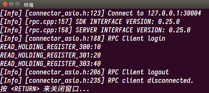
Writing a general register:
Steps for writing a Modbus general register through the SDK:
- Call
modbusAddSignalthrough the SDK to add a signal at the specified address. - Call
modbusSetOutputSignalto write the signal value at the specified address. - Call
modbusDeleteSignalto delete the signal.
- Call
Example: Use the SDK to write to the general register at address 302 in the Modbus slave. The code is as follows:
c++// Write a holding register void exampleModbusSlaveWrite(RpcClientPtr impl) { // Create a holding-register signal at the specified slave address impl->getRegisterControl()->modbusAddSignal( MODBUS_SLAVE_IP, 1, 302, 0x03, "WRITE_HOLDING_REGISTER_302", true); std::this_thread::sleep_for(std::chrono::seconds(1)); // Write a value to the holding register at the specified address impl->getRegisterControl()->modbusSetOutputSignal( "WRITE_HOLDING_REGISTER_302", 25); std::this_thread::sleep_for(std::chrono::seconds(1)); // Delete the signal when finished impl->getRegisterControl()->modbusDeleteSignal( "WRITE_HOLDING_REGISTER_302"); }Result:
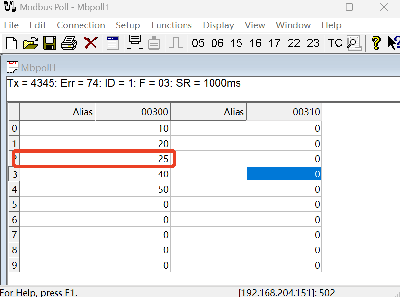
3.6.2.2 Reading and Writing General Registers Through a Project Script
Reading a general register:
Objective: Use Modbus Poll to set the value of the general register at address 300 in the Modbus slave to 10.
Example code:
lua-- Create a Modbus signal (IP, slave number, register start address, function code, name, word) modbusAddSignal("127.0.0.1,502", 1, 300, 0x03, "READ_HOLDING_REGISTER_300", true) -- Get the Modbus register value and assign it to a variable for viewing on the teach pendant tmp0 = modbusGetSignalStatus("READ_HOLDING_REGISTER_300") -- Delete the signal with the specified name modbusDeleteSignal("READ_HOLDING_REGISTER_300")Result: Write a script on the teach pendant to obtain the value of the signal at address 300. The value of
tmp0is 10.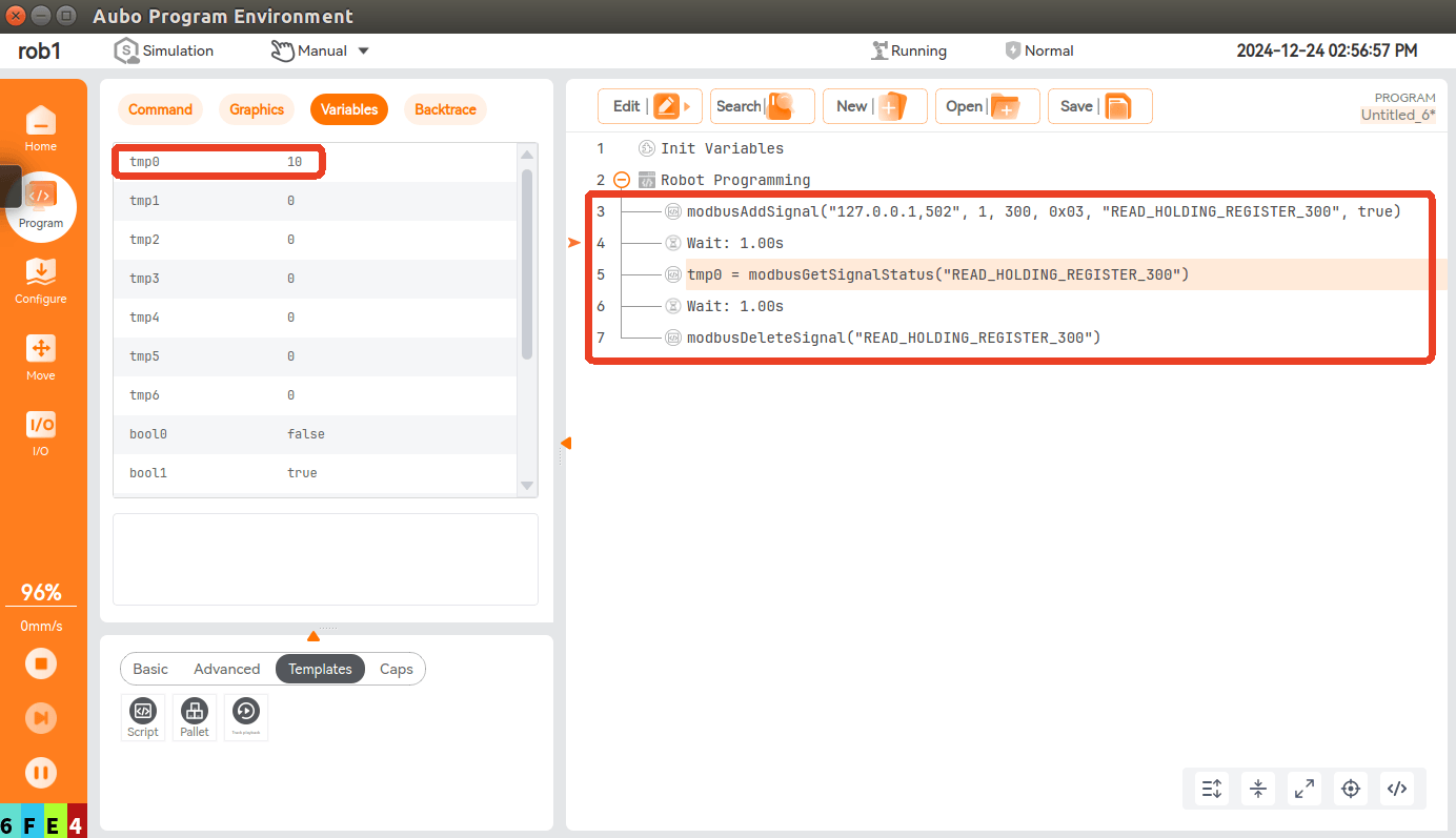
Writing a general register:
Objective: Write a script on the teach pendant to set the signal value at address 302 to 88.
Example code:
lua-- Create a Modbus signal (IP, slave number, register start address, function code, name, word) modbusAddSignal("127.0.0.1,502", 1, 302, 0x03, "WRITE_HOLDING_REGISTER_302", true) -- Write the Modbus value and assign it to a variable for viewing on the teach pendant tmp0 = modbusSetOutputSignal("WRITE_HOLDING_REGISTER_302", 88) -- Delete the signal with the specified name modbusDeleteSignal("WRITE_HOLDING_REGISTER_302")Result: Use Modbus Poll to verify that the value of the general register at address 302 is 88.
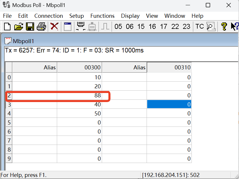
3.6.3 Reading and Writing General Registers Through Modbus RTU
Test environment:
The test uses Modbus RTU communication and calls the programming interface to communicate with the Modbus RTU slave.
Because a Modbus RTU slave does not support simultaneous connections from multiple Modbus masters during serial communication, this test does not use Modbus Poll. Instead, it calls the interface to obtain the signal value at the specified address and checks whether the signal changes correctly.
Select two serial port numbers that can communicate. This test uses
/dev/ttyS0and/dev/ttyS1./dev/ttyS1is assigned to the Modbus RTU slave, and/dev/ttyS0is used by the programming interface.Enable the Modbus RTU slave. The relevant configuration is shown below:
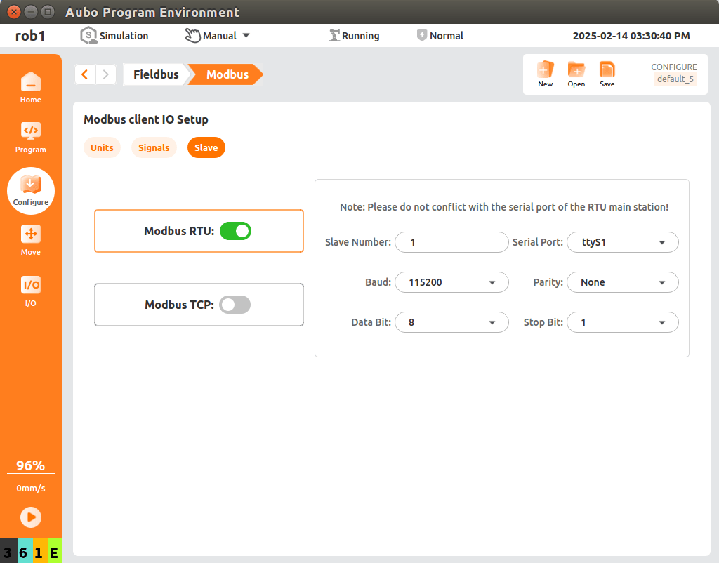
Important
During serial communication, make sure that both serial ports can communicate normally. You can use a debugging assistant such as CuteCom to verify the connection.
A serial port number cannot be used by multiple masters or slaves at the same time.
3.6.3.1 Reading and Writing General Registers Through the SDK
Example flow for reading and writing a general register through the SDK:
- Call
modbusAddSignalto add a signal at the specified address. - Call
modbusGetSignalStatusto read the signal value at the specified address and view its initial value. - Call
modbusSetOutputSignalto write a signal value at the specified address. - Call
modbusGetSignalStatusto read the signal value at the specified address. - Call
modbusDeleteSignalto delete the signal when finished.
- Call
The following example reads and writes the general register at address 302 in the Modbus slave through the SDK:
c++// Read and write a holding register through Modbus RTU #define MODBUS_SERIAL_PORT "/dev/ttyS0,115200,N,8,1" void exampleModbusRtu(RpcClientPtr impl) { // Create a holding-register signal at the specified slave address impl->getRegisterControl()->modbusAddSignal( MODBUS_SERIAL_PORT, 1, 302, 0x03, "HOLDING_REGISTER_302", true); std::this_thread::sleep_for(std::chrono::seconds(1)); // Get the value of the holding-register signal at the specified address auto ret0 = impl->getRegisterControl()->modbusGetSignalStatus( "HOLDING_REGISTER_302"); std::cout << "Read --> HOLDING_REGISTER_302:" << ret0 << std::endl; // Write a value to the holding register at the specified address impl->getRegisterControl()->modbusSetOutputSignal("HOLDING_REGISTER_302", 66); std::cout << "Write 66 to HOLDING_REGISTER_302" << std::endl; std::this_thread::sleep_for(std::chrono::seconds(1)); // Get the value of the holding-register signal at the specified address auto ret1 = impl->getRegisterControl()->modbusGetSignalStatus( "HOLDING_REGISTER_302"); std::cout << "Read --> HOLDING_REGISTER_302:" << ret1 << std::endl; std::this_thread::sleep_for(std::chrono::seconds(1)); // Write a value to the holding register at the specified address impl->getRegisterControl()->modbusSetOutputSignal("HOLDING_REGISTER_302", 88); std::cout << "Write 88 to HOLDING_REGISTER_302" << std::endl; std::this_thread::sleep_for(std::chrono::seconds(1)); // Get the value of the holding-register signal at the specified address auto ret2 = impl->getRegisterControl()->modbusGetSignalStatus( "HOLDING_REGISTER_302"); std::cout << "Read --> HOLDING_REGISTER_302:" << ret2 << std::endl; std::this_thread::sleep_for(std::chrono::seconds(1)); // Delete the signal when finished impl->getRegisterControl()->modbusDeleteSignal( "HOLDING_REGISTER_302"); }The output shows that the initial value of the general register at address 302 is 0. After writing 66, the read value is 66. After writing 88, the read value is 88. This indicates that the SDK can read and write the general register in the Modbus slave normally.
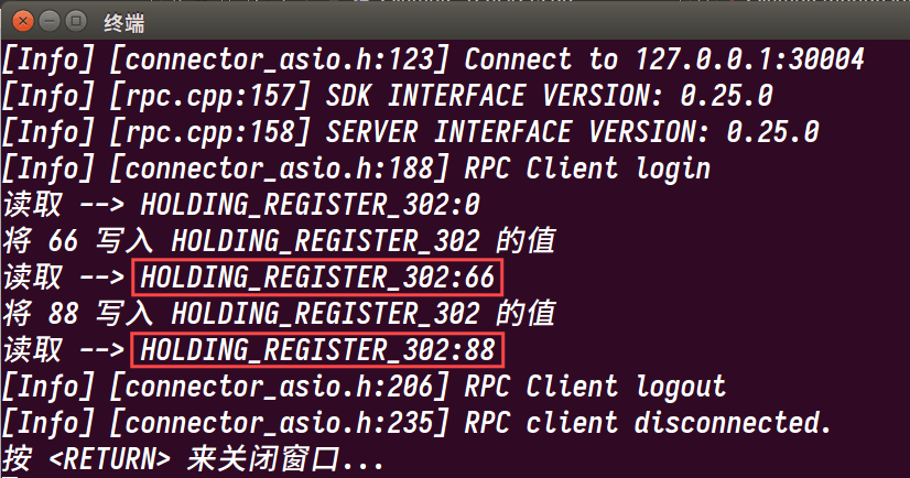
3.6.3.2 Reading and Writing General Registers Through a Project Script
Objective: Write a script on the teach pendant to perform the following flow. Assign each read value to
tmp0:- Call
modbusGetSignalStatusto obtain the signal value at address 300. - Call
modbusSetOutputSignalto set the signal value at address 300 to 88. - Call
modbusGetSignalStatusto obtain the signal value at address 300. - Call
modbusSetOutputSignalto set the signal value at address 300 to 66.
- Call
Example code:
lua-- Create a Modbus signal (device information, slave number, register start address, function code, name, word) modbusAddSignal("/dev/ttyS0,115200,N,8,1", 1, 300, 0x03, "HOLDING_REGISTER_300", true) -- Get the Modbus register value and assign it to a variable for viewing on the teach pendant tmp0 = modbusGetSignalStatus("HOLDING_REGISTER_300") -- Write the Modbus value modbusSetOutputSignal("HOLDING_REGISTER_300", 88) -- Get the Modbus register value and assign it to a variable for viewing on the teach pendant tmp0 = modbusGetSignalStatus("HOLDING_REGISTER_300") -- Write the Modbus value modbusSetOutputSignal("HOLDING_REGISTER_300", 66) -- Get the Modbus register value and assign it to a variable for viewing on the teach pendant tmp0 = modbusGetSignalStatus("HOLDING_REGISTER_300") -- Delete the signal with the specified name modbusDeleteSignal("HOLDING_REGISTER_300")Result: The value of
tmp0changes between 66 and 88.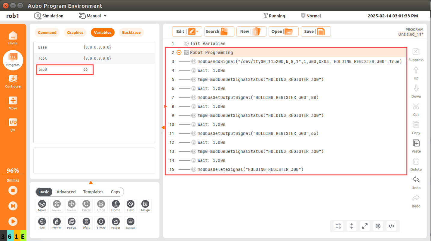
4. Interface Applications
4.1 modbusSendCustomCommand Function and Notes
- Sends a user-specified command to the Modbus unit at the specified IP address.
- Because no response is received, the function cannot be used to request data. Read function codes are not currently available.
- The user is responsible for providing data that is meaningful for the specified function code.
- The built-in function constructs the Modbus frame. You do not need to calculate the command length or enter CRC data.
4.2 Parameter Definitions and Formats
// Interface definition
int modbusSendCustomCommand(const std::string &device_info, int slave_number,
                            int function_code, const std::vector<uint8_t> &data);

// device_info: device information
     * RTU format:
     * "serial_port,baud,parity,data_bit,stop_bit"
     * (1) serial_port specifies the serial port name.
     *     For example, "/dev/ttyS0" or "/dev/ttyUSB0" on Linux,
     *     and "\\.\\COM10" on Windows.
     * (2) baud specifies the communication baud rate, such as 9600, 19200,
     *     57600, or 115200.
     * (3) parity specifies the parity mode. N means no parity, E means even
     *     parity, and O means odd parity.
     * (4) data_bit specifies the number of data bits. Valid values are 5, 6,
     *     7, and 8.
     * (5) stop_bit specifies the number of stop bits. Valid values are 1 and 2.
     *
     * TCP format: "ip address,port"
     * (1) ip address specifies the server IP address.
     * (2) port specifies the port on which the server listens.

// slave_number: slave number used for the custom command

// function_code: function code for the custom command
     * MODBUS_FC_READ_COILS                0x01   // Read coil registers
     * MODBUS_FC_READ_DISCRETE_INPUTS      0x02   // Read discrete input status
     * MODBUS_FC_READ_HOLDING_REGISTERS    0x03   // Read holding registers
     * MODBUS_FC_READ_INPUT_REGISTERS      0x04   // Read input registers
     * MODBUS_FC_WRITE_SINGLE_COIL         0x05   // Write a single coil
     * MODBUS_FC_WRITE_SINGLE_REGISTER     0x06   // Write a single register
     * MODBUS_FC_READ_EXCEPTION_STATUS     0x07   // Read exception status (serial line only)
     * MODBUS_FC_WRITE_MULTIPLE_COILS      0x0F   // Write multiple coils
     * MODBUS_FC_WRITE_MULTIPLE_REGISTERS  0x10   // Write multiple registers
     * MODBUS_FC_REPORT_SLAVE_ID           0x11   // Report slave ID (serial line only)
     * MODBUS_FC_MASK_WRITE_REGISTER       0x16   // Mask write register
     * MODBUS_FC_WRITE_AND_READ_REGISTERS  0x17   // Read and write registers

// data: valid byte values from 0 to 255
     * { 0x00, 0x02, 0x00, 0x0F }
     * { 0x06, 0x0A, 0x0F, 0x08, 0x00, 0x0F }
4.3 Calling Example
// Define the IP address
#define MODBUS_IP          "172.16.3.111,502"
// Create the object
RpcClientPtr impl;
// Send custom data
impl->getRegisterControl()->modbusSendCustomCommand(
    MODBUS_IP, 1, 0x06, { 0x00, 0x02, 0x00, 0x0F });
5. Troubleshooting
5.1 Modbus TCP Signal Communication Failure
Follow these steps to troubleshoot the failure:
- Check whether the network between the device and the robot can communicate normally. First check whether the device firewall is disabled, then use the
pingcommand to check network communication. - Check whether the signal address created by the master exists in the slave. The address corresponding to the signal created by the master must exist in the slave for the signal to communicate normally.
- Check whether the robot IP address conflicts with the IP address of another device on the same local network.
5.2 Modbus RTU Signal Communication Failure
- Check whether serial communication between the device and the robot is normal. Use a serial port debugging assistant on the device and robot to test the serial communication status.
- Check whether the signal address created by the master exists in the slave. The address corresponding to the signal created by the master must exist in the slave for the signal to communicate normally.
Operational steps:
Install
cutecomin the robot controller using the command.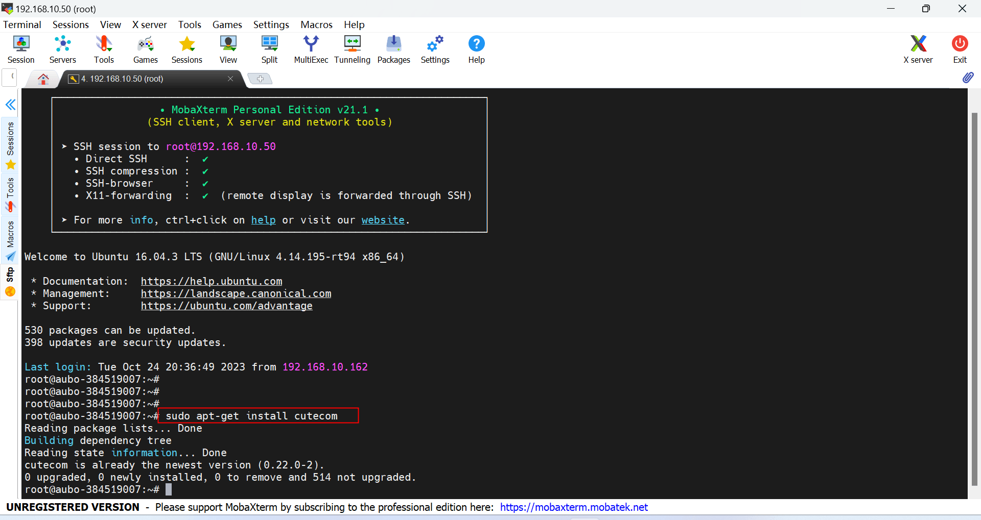
Open CuteCom and set the Serial Port, Baud Rate, Parity, Data Bits, and Stop Bits.
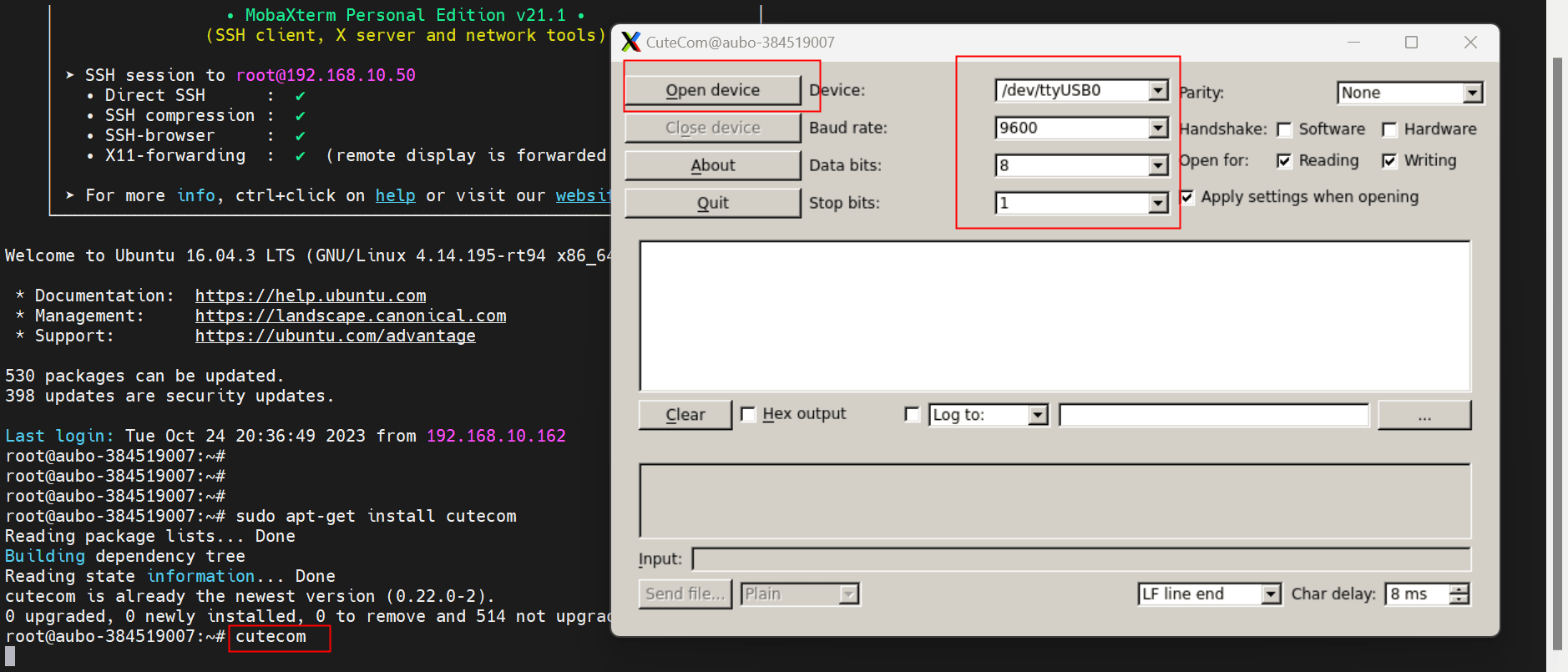
If the device is a PLC, use CuteCom to connect directly to the PLC for testing. If the device is a local computer, install a serial port debugging assistant such as
XCOMon the computer.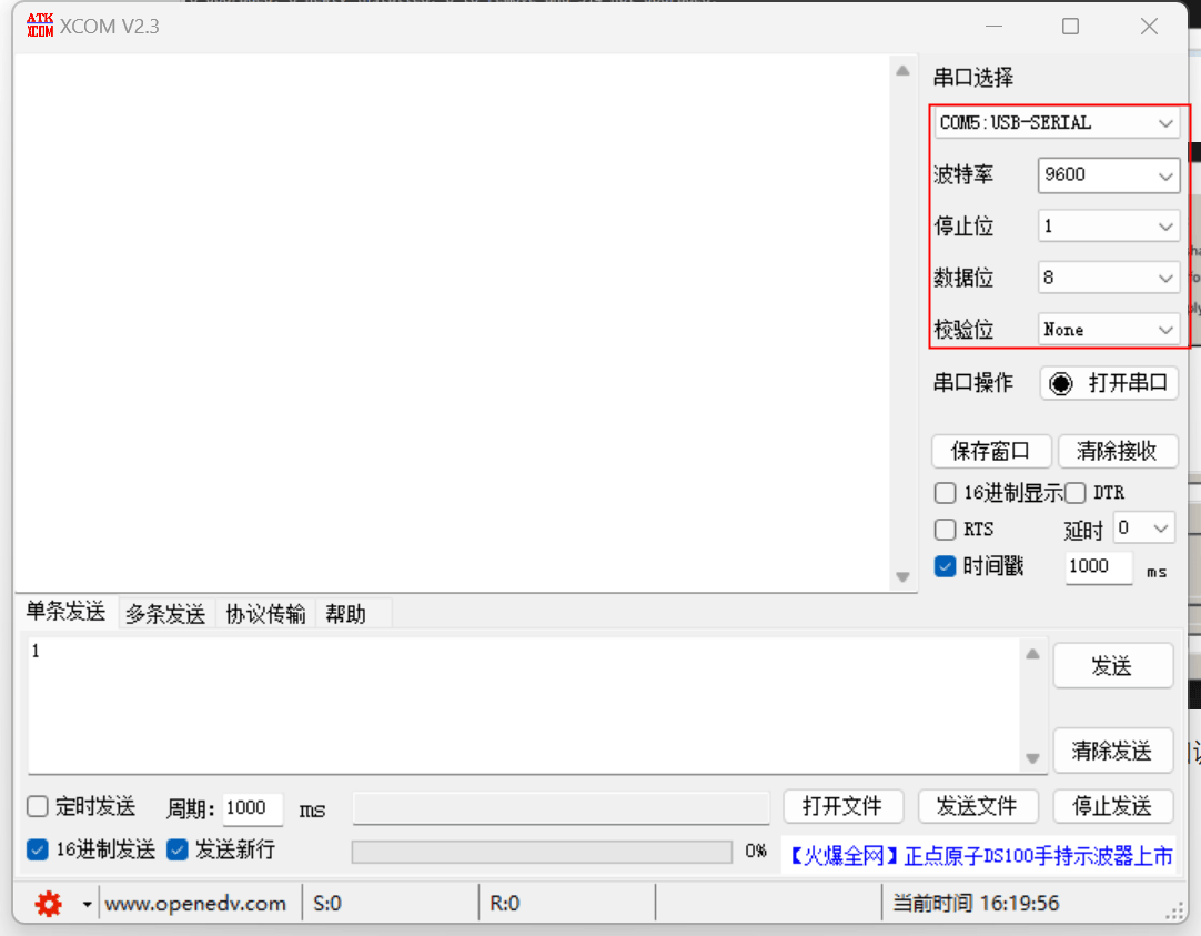
If CuteCom and the PLC or XCOM can send data to each other, communication is normal and the serial communication wiring is not faulty. Otherwise, check the communication wiring.
6. Frequently Asked Questions
6.1 Q1. When using a wireless teach pendant with a router to bridge the network, the IP address can be reached by ping, but the Modbus master signal does not communicate.
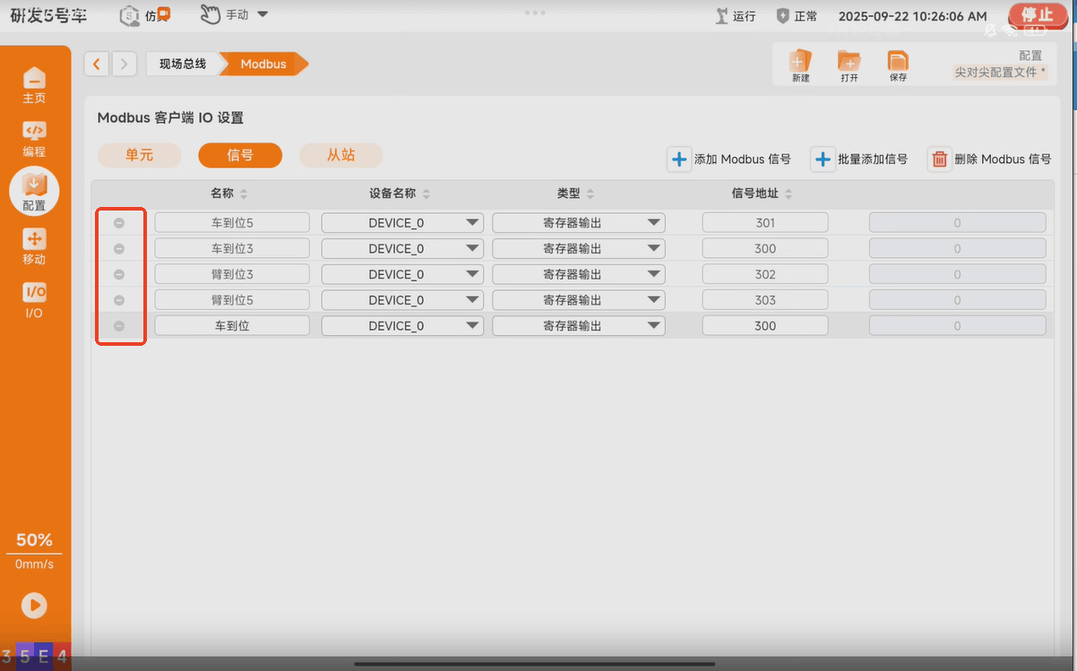
Solution: Check whether port forwarding is configured on the router. If it is not configured, add the port used by Modbus TCP.