ICM to Soft Protocol Stack Migration Guide
1 Pre-Migration Preparation
1.1 System Environment Check
- Check and record the ARCS software version currently in use;
- Check and record the ICM version currently in use. If an OEM package is used, record the OEM version number; if an ICM installer is used, record the ICM version number;
1.2 Data Backup
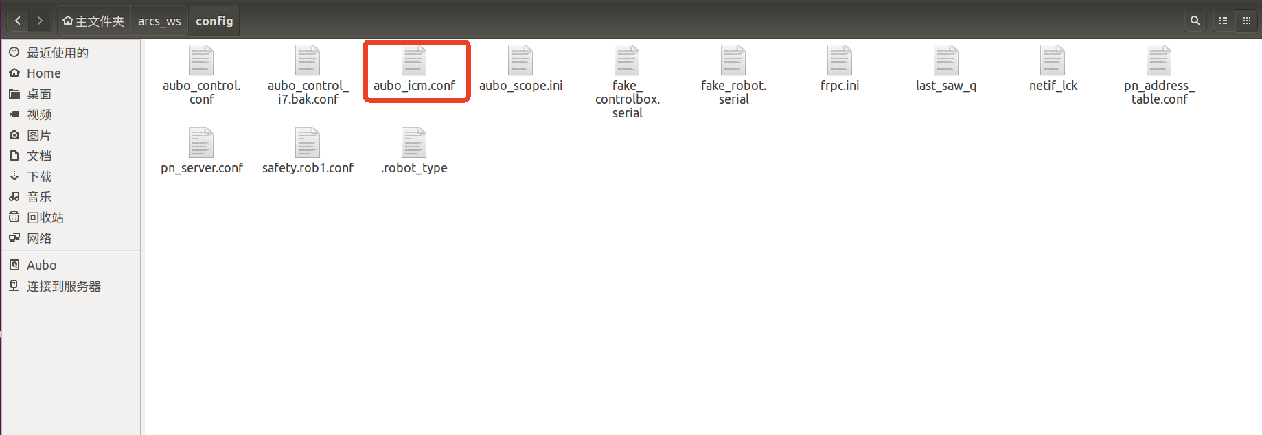
Prepare a USB drive, open the file manager, navigate to the file path ~/arcs_ws/config/, back up the ICM configuration file aubo_icm.conf, and copy the following files out;
1.3 Uninstalling ICM
1.3.1 Uninstalling ICM Installed from a .run Installer
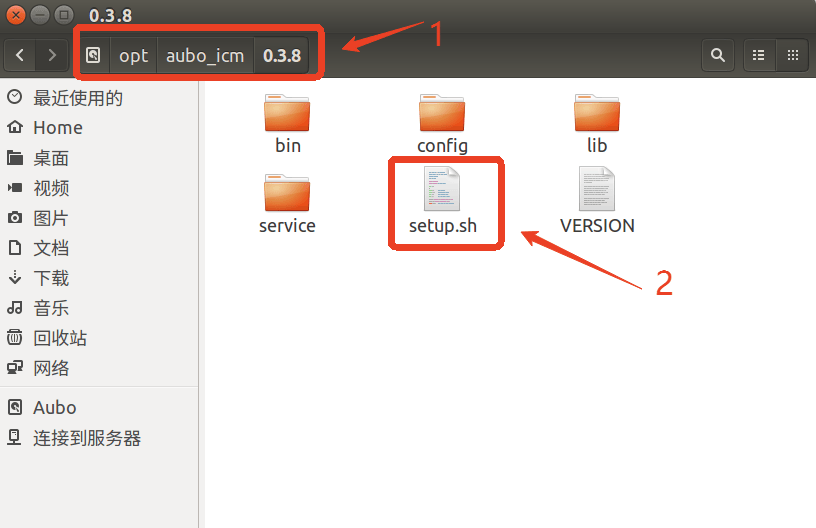
(1) Open the file manager, navigate to the file path /opt/aubo_icm/XXXX, find the script file setup.sh, then open the terminal here and start entering the relevant commands;
(2)Enter the following command to uninstall aubo_icm. The printed log during uninstallation is shown in the figure below; when the following log content appears, it means the aubo_icm service has been stopped and uninstalled successfully;
# Add executable permission to the script
chmod +x setup.sh
# Run the uninstall command
sudo ./setup.sh uninstall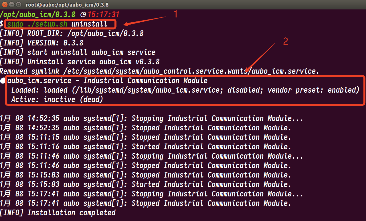
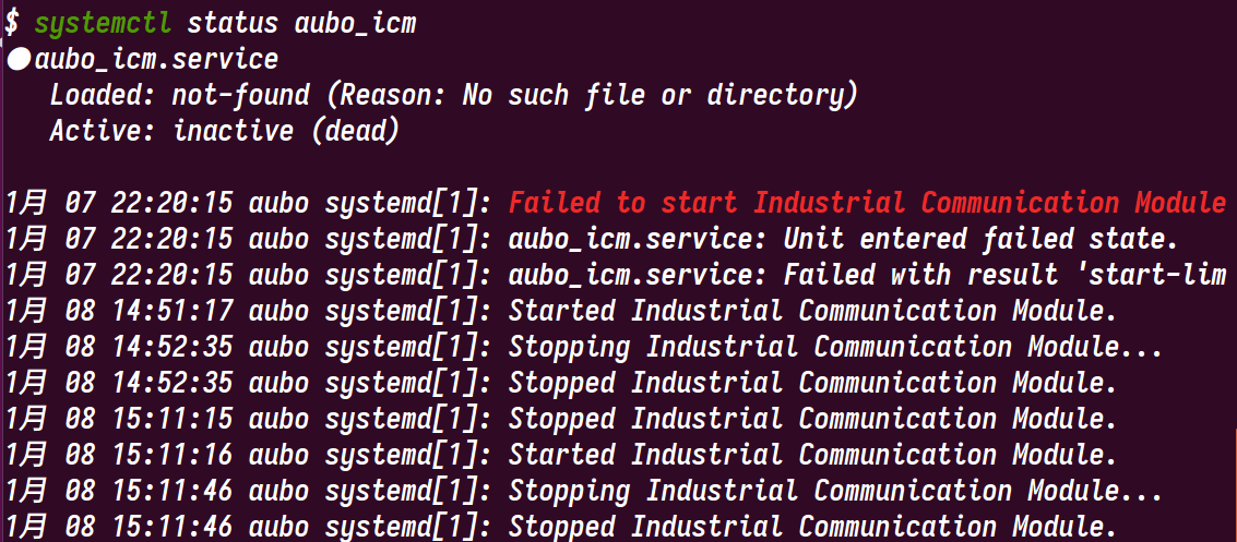
(3) After uninstalling with the command, you can use systemctl status aubo_icm to check and confirm whether the service has been uninstalled successfully. The following log indicates that the aubo_icm service has been uninstalled successfully;
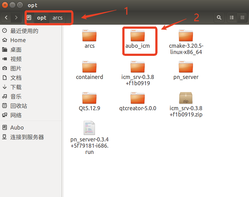
(4)After uninstalling with the command and confirming that the aubo_icm service no longer exists, navigate to the /opt/arcs/ directory, find the aubo_icm folder, and manually delete this folder;
1.3.2 Uninstalling ICM Installed from an OEM Package
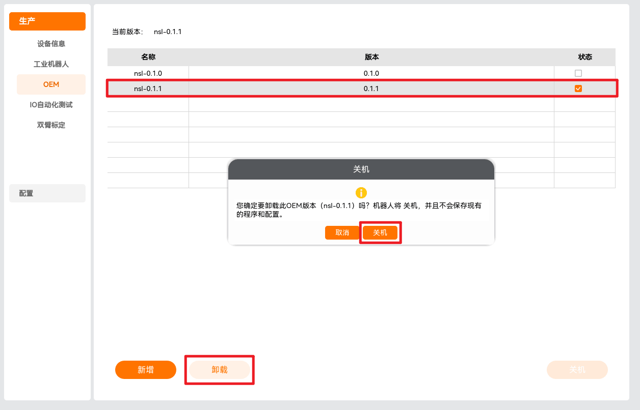
(1)Uninstall the OEM package via the teach pendant
Select the OEM version currently in use, click [Uninstall], confirm, and then restart the controller to uninstall the OEM currently in use. After the controller restarts, click "Home > About" to open the [About] prompt box and check whether the OEM package has been uninstalled successfully.
(2)Uninstall the OEM package via command (optional)
# Switch to the target arcs version
cd /opt/arcs/xxx
./setup.sh uninstall_oem
# Delete the OEM_VERSION field
sed -i '$d' /etc/default/arcs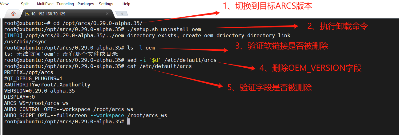
Remarks:
(1)After the OEM package is uninstalled, if you want to continue using the OEM's customized features, please contact FAE or R&D personnel to re-customize the OEM package (excluding ICM);
(2)From now on, ICM will provide gateway service functionality in the form of a
.runinstaller. Please contact FAE or R&D personnel for the latest ICM installer;
1.4 Preparing the Relevant Installation Packages
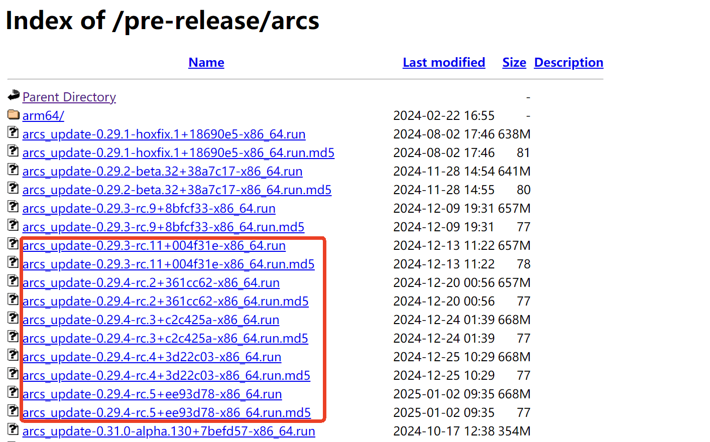
(1)To migrate EIP, prepare an arcs installer that supports soft EIP. Currently, the arcs version requires 0.29.3-rc.9 or later, which can be downloaded from the official website;
Download address: https://download.aubo-robotics.cn/pre-release/arcs/
(2)To migrate Profinet, prepare the soft Profinet installer and installation scripts, etc.;

Download address: https://download.aubo-robotics.cn/pre-release/extensions/
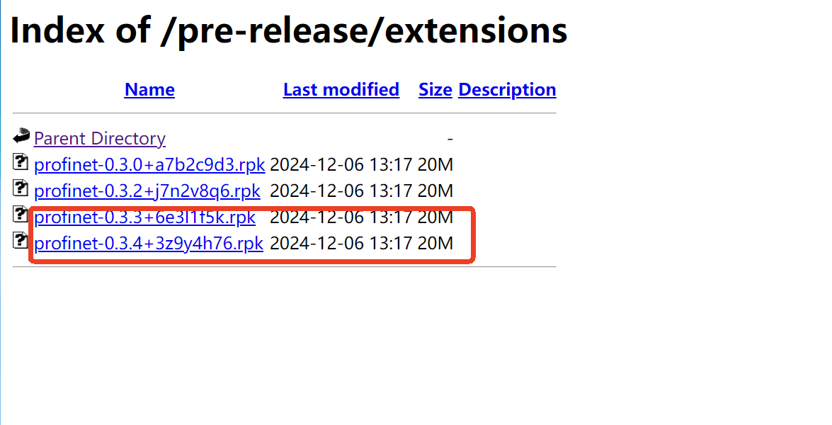
Remark: the installer and installation scripts can be obtained from FAE or R&D personnel. Please use the newest software version as much as possible;
2 Detailed EIP Migration Steps
2.1 Data Backup
Back up the ICM configuration file. Prepare a USB drive, navigate to the path ~/arcs_ws/config/, back up the ICM configuration file aubo_icm.conf, and copy this file out;
2.2 System Environment Check
Check whether the arcs version currently in use supports soft EIP. If it does not, migration cannot be performed; if migration is required, the arcs software version must be upgraded;
arcs versions that support soft eip:
- [0.32.0-alpha.10] and later;
- [0.31.0-beta.2] and later;
- [0.29.3-rc.9] and later;
Remark: for the specific version to which you can upgrade, please consult the relevant FAE personnel;
2.3 Soft EIP Configuration
2.3.1 Modifying the Configuration File
After updating to the arcs software version that includes soft EIP, modify the configuration file aubo_control.conf and add the following code:
eip_enable = true
# Change the network interface name according to the actual situation
eip_ifname = "enp1s0"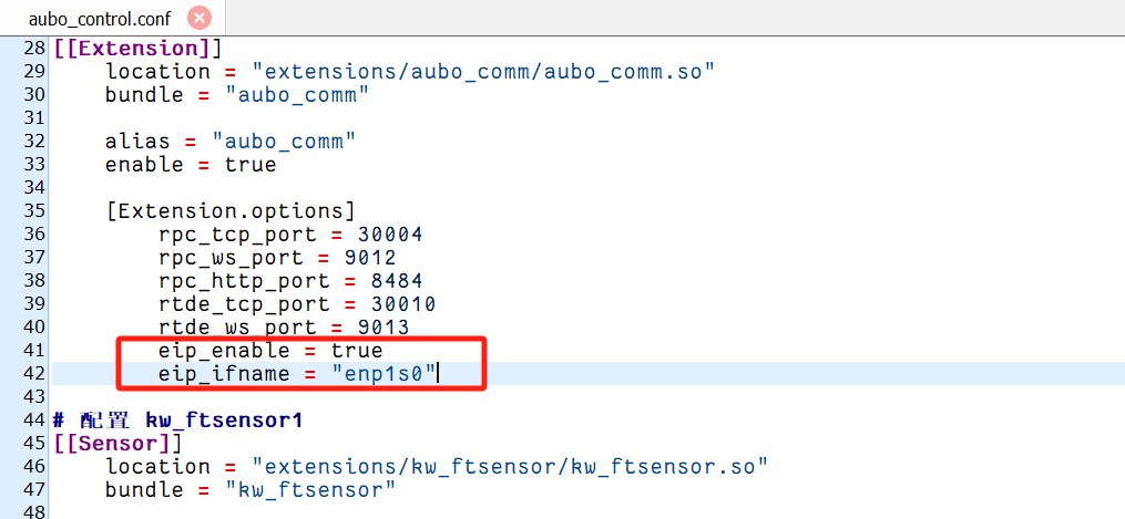
2.3.2 Checking Whether Installation Succeeded
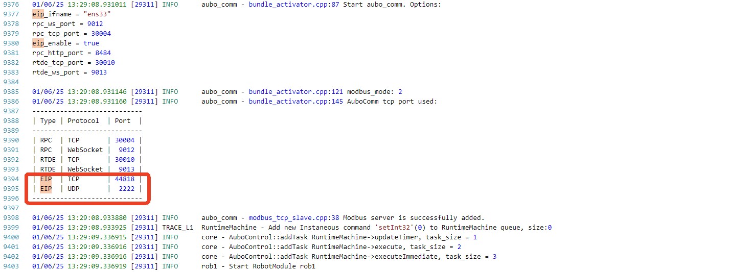
Restart the arcs software. After a successful installation, the controller's log will print the following log:
2.4 Soft EIP Test Verification
2.4.1 Functional Verification Environment Preparation
Click Download resource package
and install the Inovance PLC debugging softwareAutoShopAutoShop software
Version:V4.10.0.0EDS file
compatible_eip_slave_v0.0.1.edsHardware
InovanceEasy 521robot body, laptop, network cable, HUB or switch
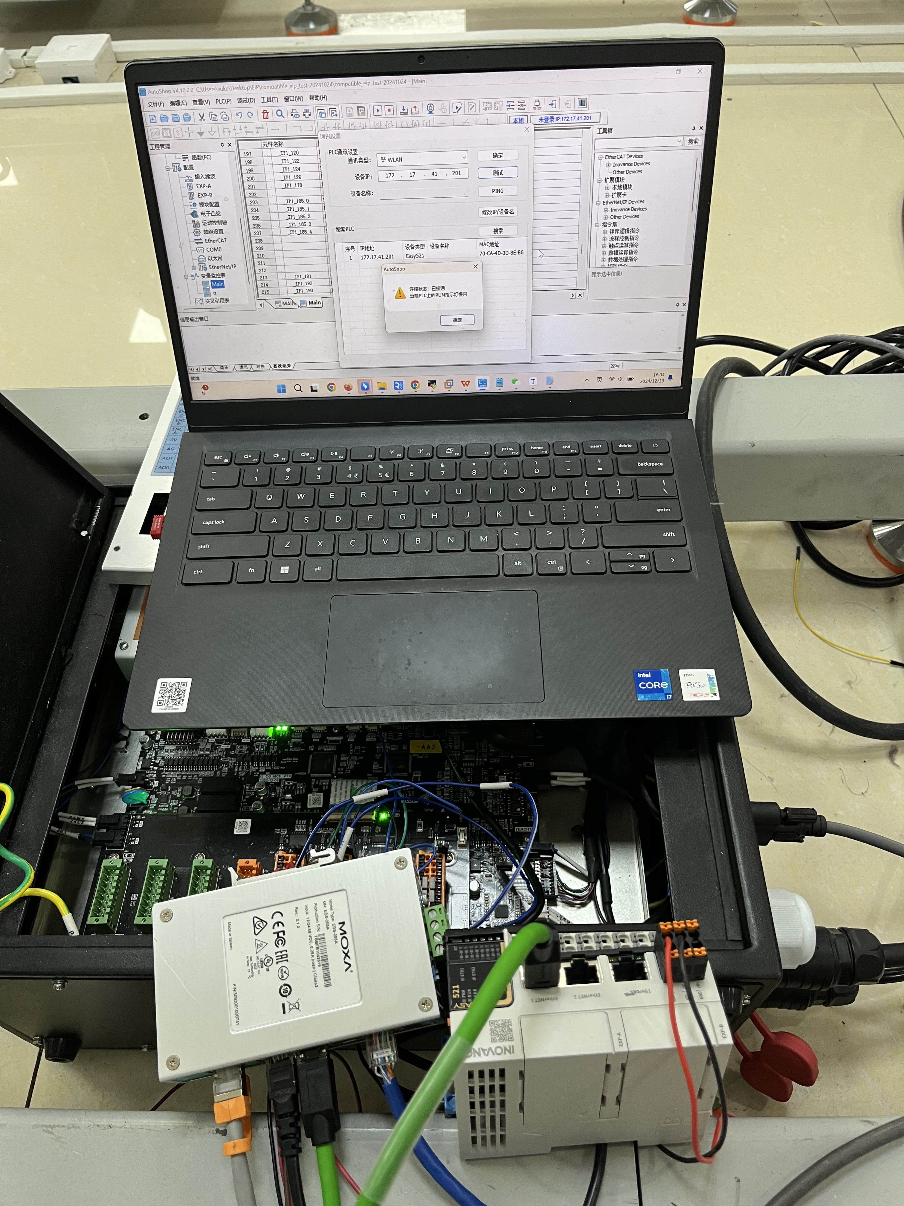
2.4.2 Hardware Wiring
Connect the PLC, the control cabinet, and the local computer to the same network via a switch;
2.4.3 Setting a Static IP on the PLC
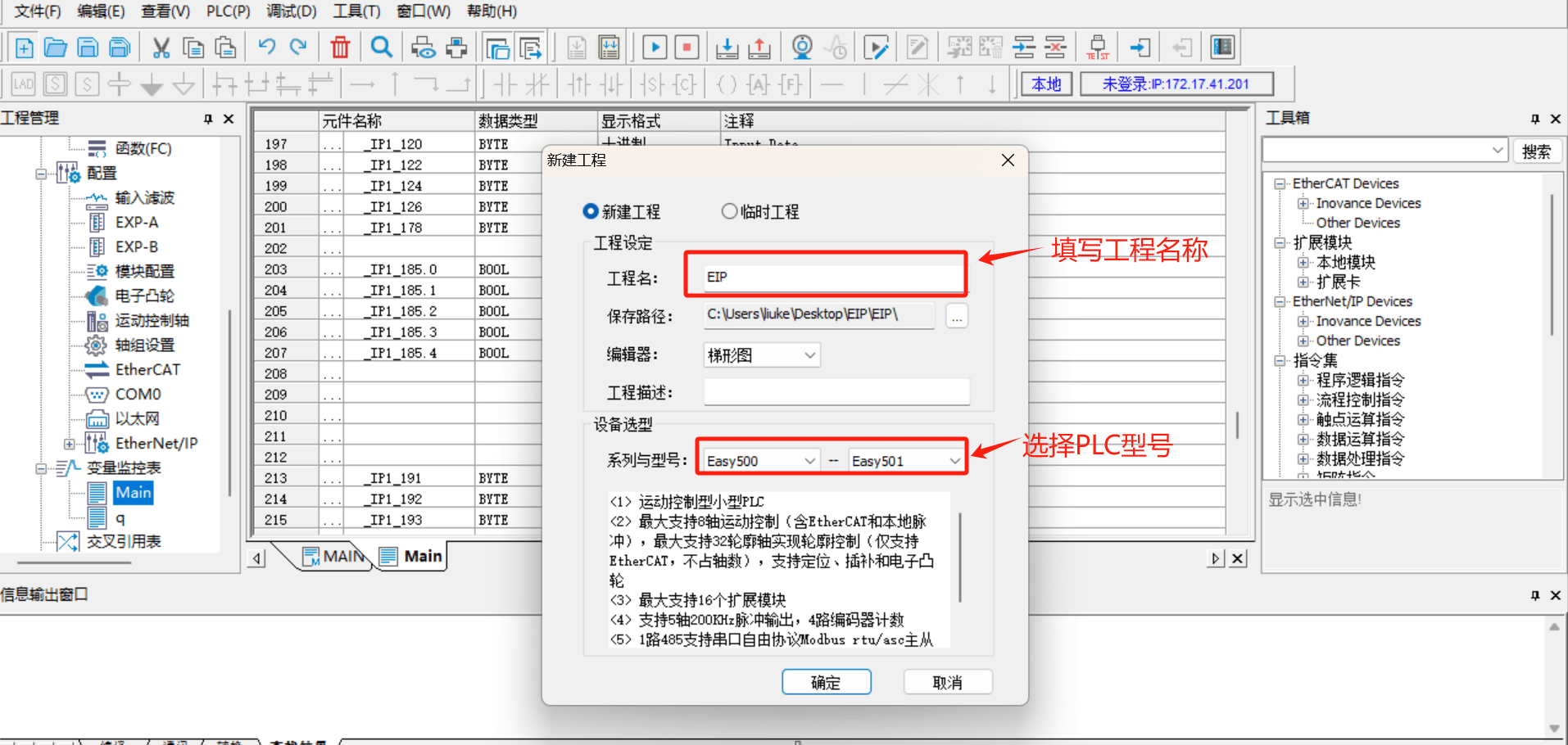
Double-click to open the AutoShoop software, enter the main page, select [File] > [New Project] as shown in the figure below, and follow the marked steps in the figure to fill in the project name and select the Inovance PLC model Easy521;
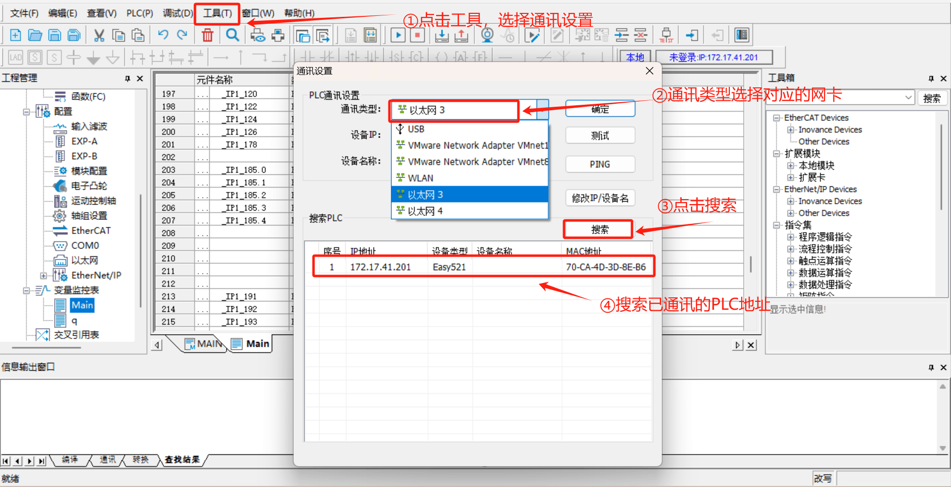
Click Tools in the menu bar, select Communication Settings, select the corresponding network port from the Communication Type drop-down box, and click Search PLC. After a normal connection, the PLC that is already communicating can be found;
Click Modify IP/Device Name and set a new IP address. This address must be in the same network segment as the robot arm and the laptop;
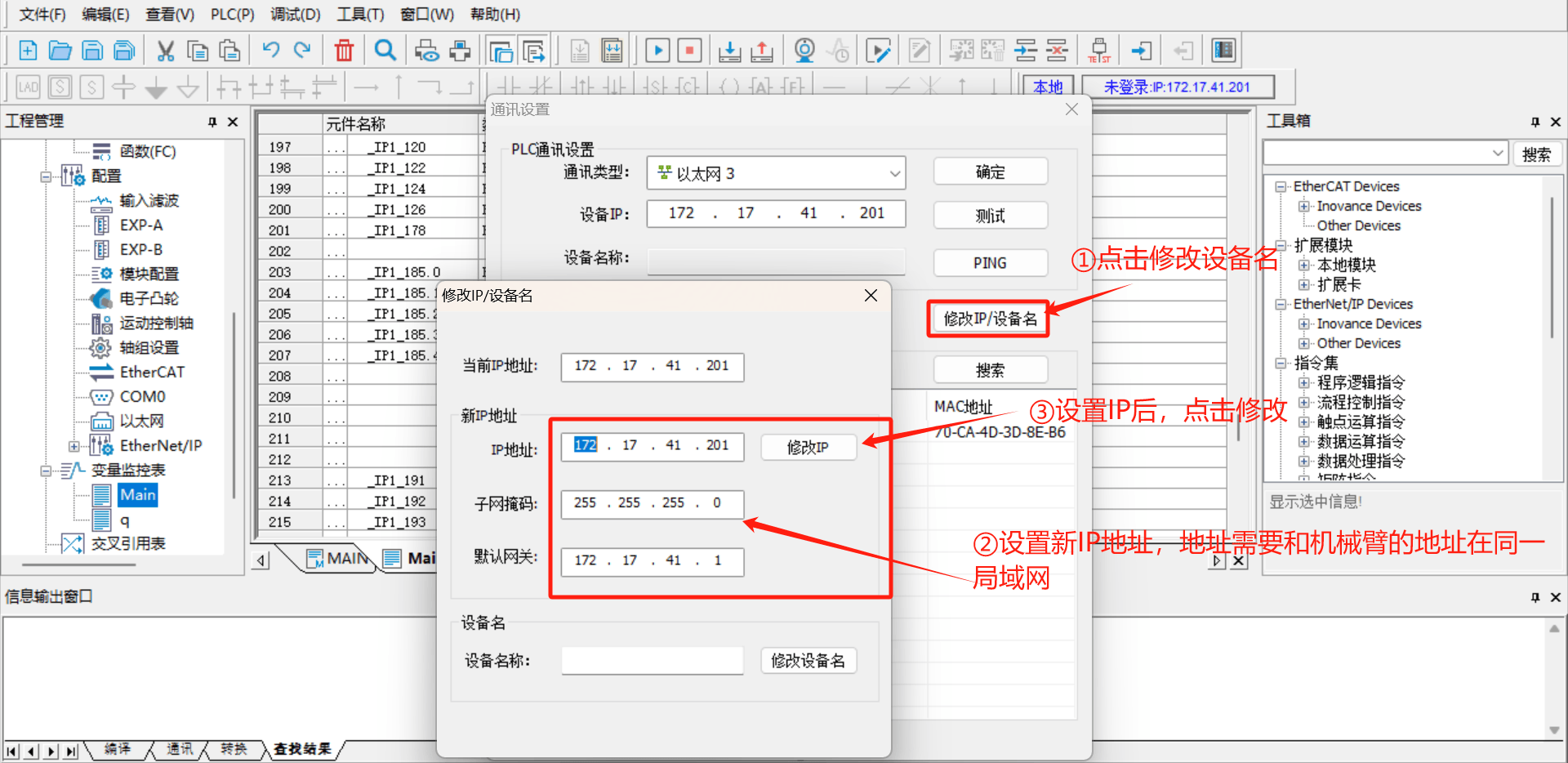
Remark: if the PLC cannot be found online, use a
type-C-to-USB cable to connect the PLC to the laptop, selectUSBas the communication type, and you can modify the IP of the PLC device;
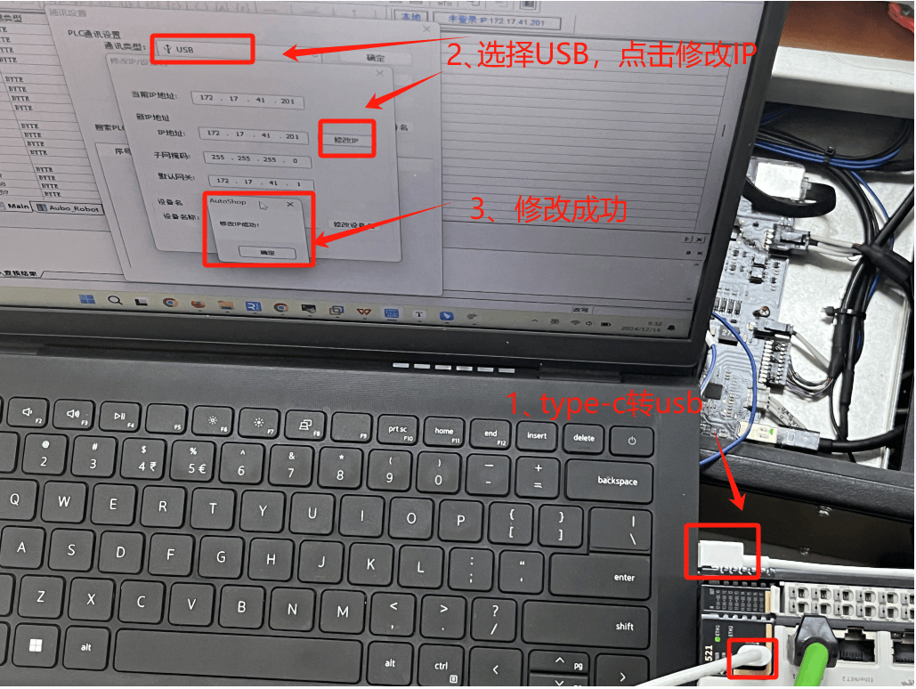
2.4.4 Setting a Static IP on the Robot Arm
Open the arcs software and set a static IP. The static IP address must be in the same network segment as the PLC and the laptop;
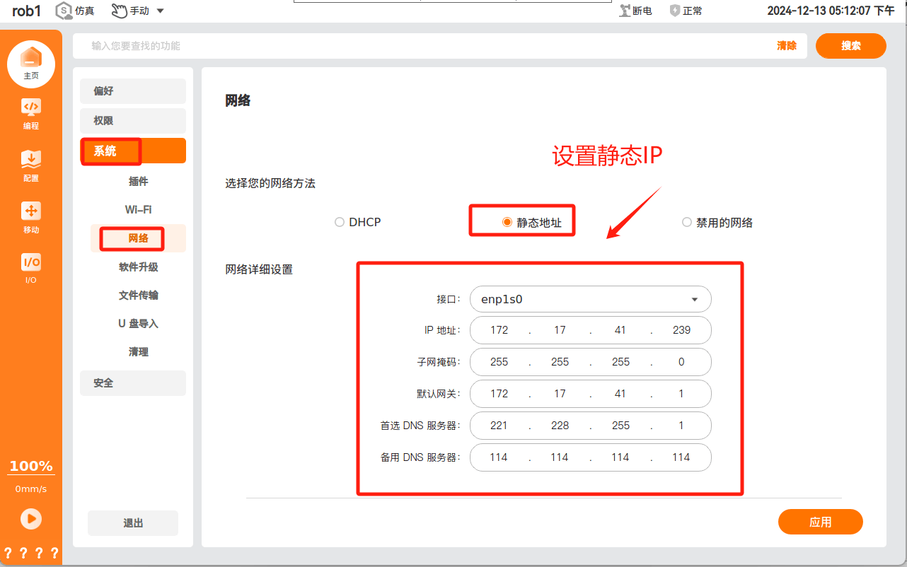
2.4.5 Communication Test
Click Test. When the connection status is connected, the PLC and the laptop have established normal communication;
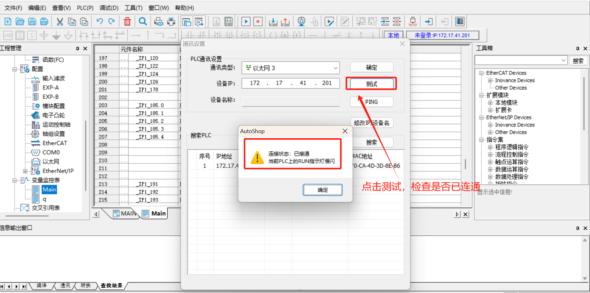
If the test connection status is not connected, check the network cable connection and whether the PLC's IP setting is in the same network segment as the laptop;
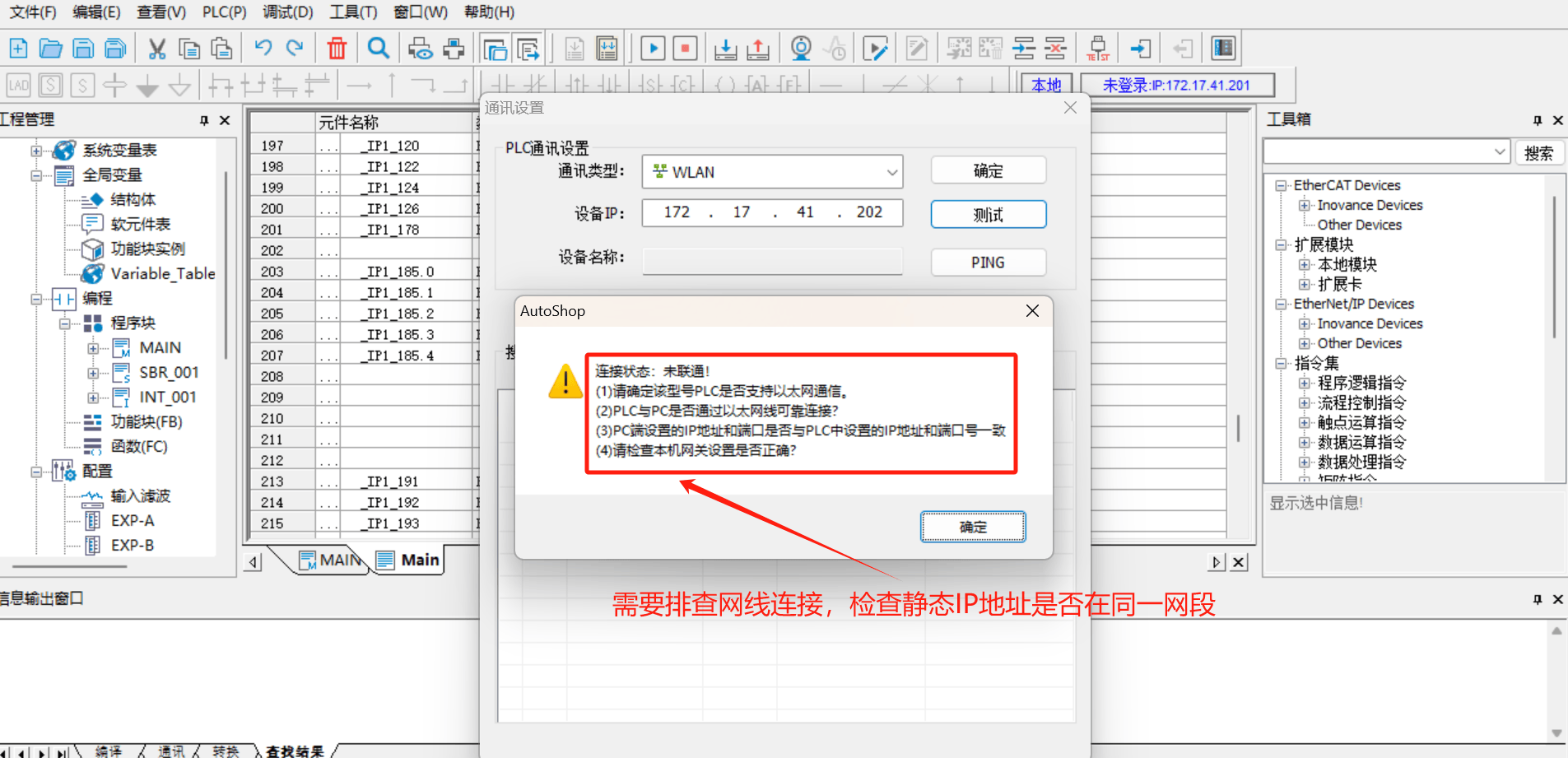
2.4.6 Importing the EDS File into the PLC
Click [Project Management] > [Configuration] > [Ethernet/IP] on the left side of the software; click [Toolbox] > [Ethernet/IP Device] on the right-side menu bar of the software, right-click [Ethernet/IP Device], and [Import EDS] will appear. Click [Import EDS] to import the EDS file prepared in advance; as shown in the figure below:
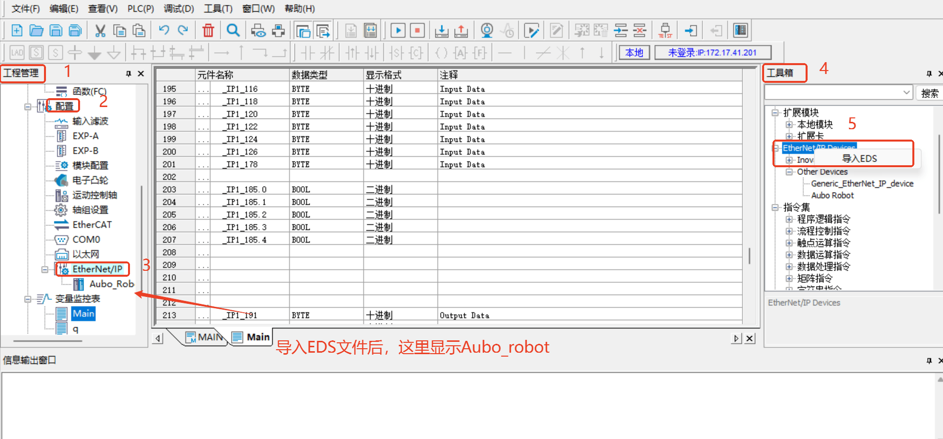
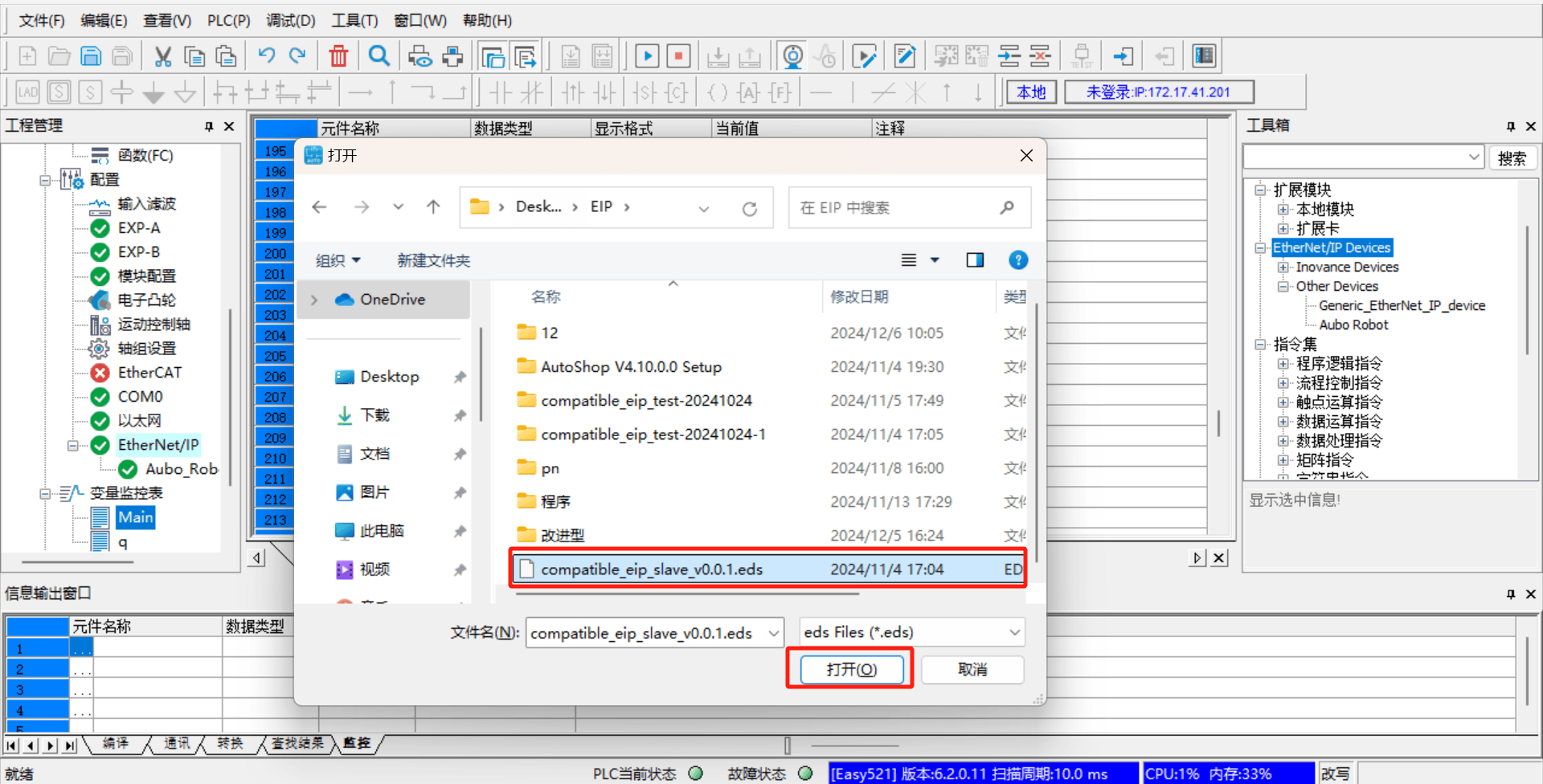
Remark: the EDS file is provided by AUBO developers; you can obtain the latest version from the relevant engineers;
2.4.7 Device Station IP Settings
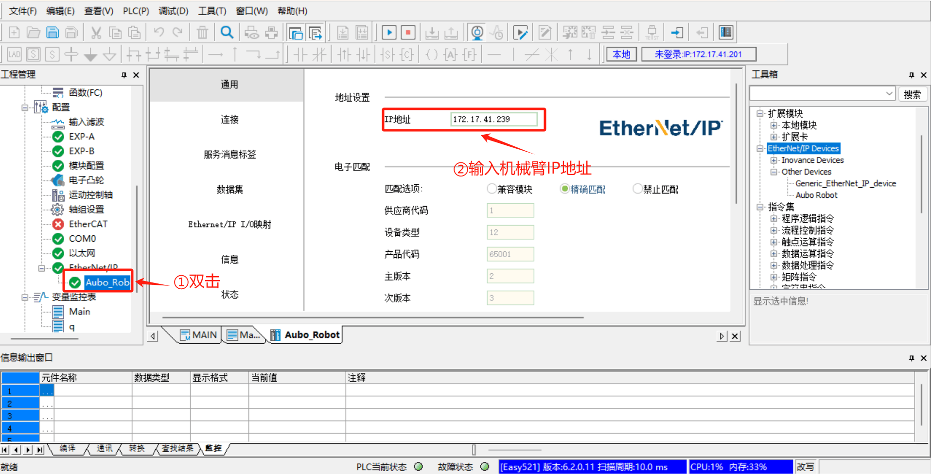
Double-click [Aubo_Robot], set IP Address to the robot arm's real IP; select Exact Match in Electronic Matching, and use the default values for the rest, as shown in the figure below:
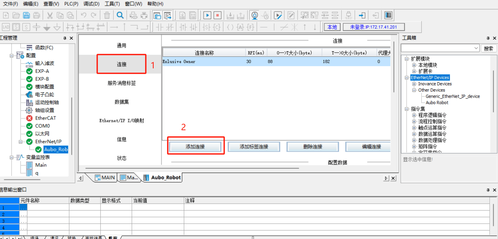
Click [Connection] > [Add Connection]
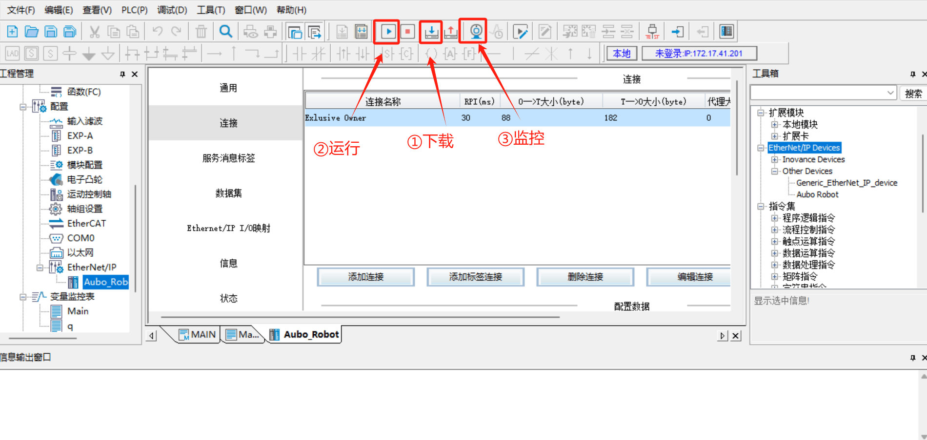
2.4.8 Save Project > Download > Run > Monitor
After all configurations are complete, save the project, then click [Download] > [Run] > [Monitor], as shown in the steps in the figure below:
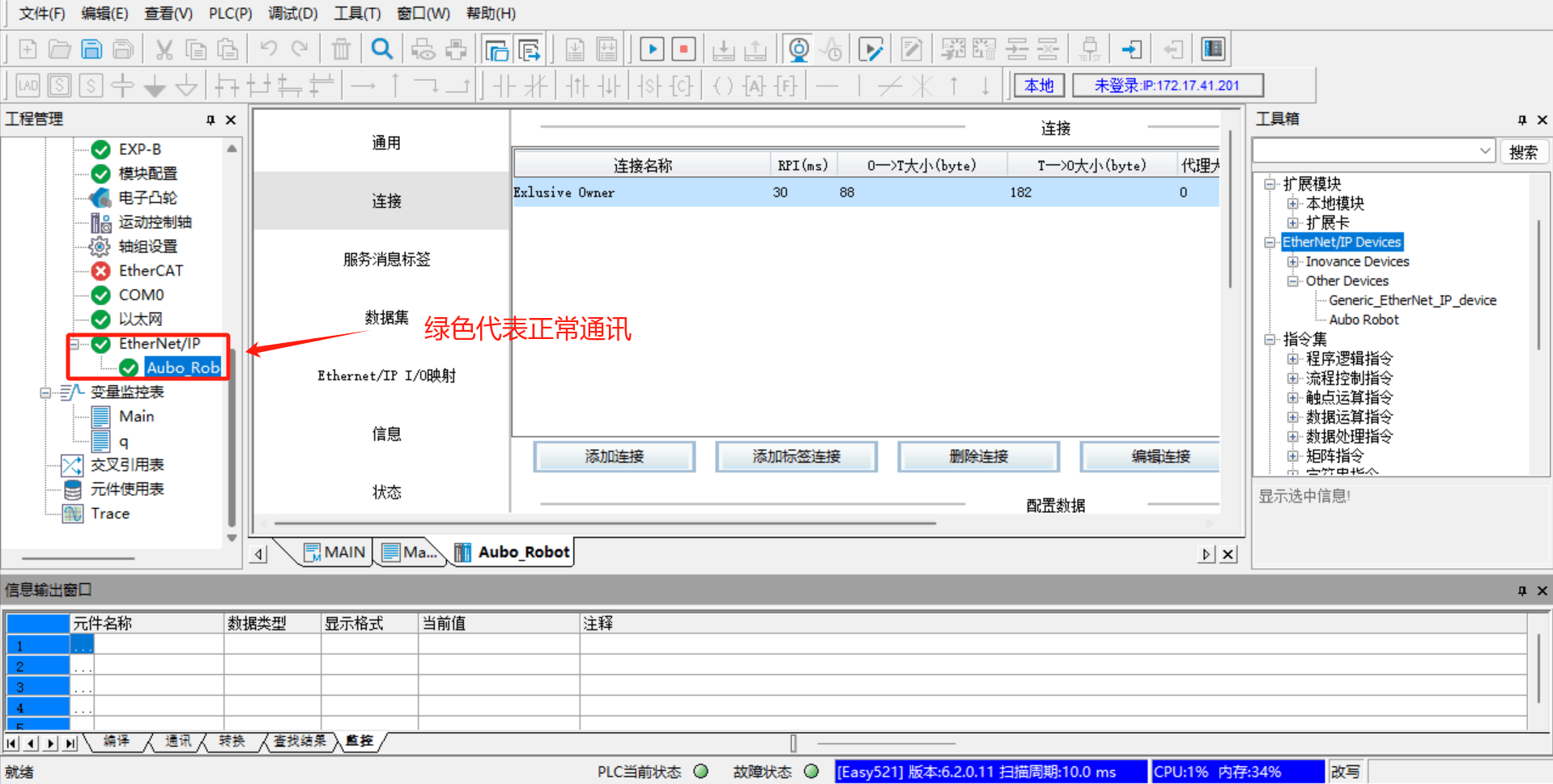
Switch the PLC to run mode. After clicking [Run] > [Monitor], in the left-side [Configuration] > [Ethernet/IP], both [Ethernet/IP] and [Aubo_Robot] turn green, indicating that the PLC and the robot arm are connected successfully and can communicate normally;
2.4.9 Online Monitoring of Address Signals
Add the address variable to be monitored. On the left side, click [Variable Monitor Table] > [Main], and in the Main table click [...] to open the variable selection dialog [Variable Input Assistant], then click [UserVar] > [SYS_EIP] to select the assigned address;
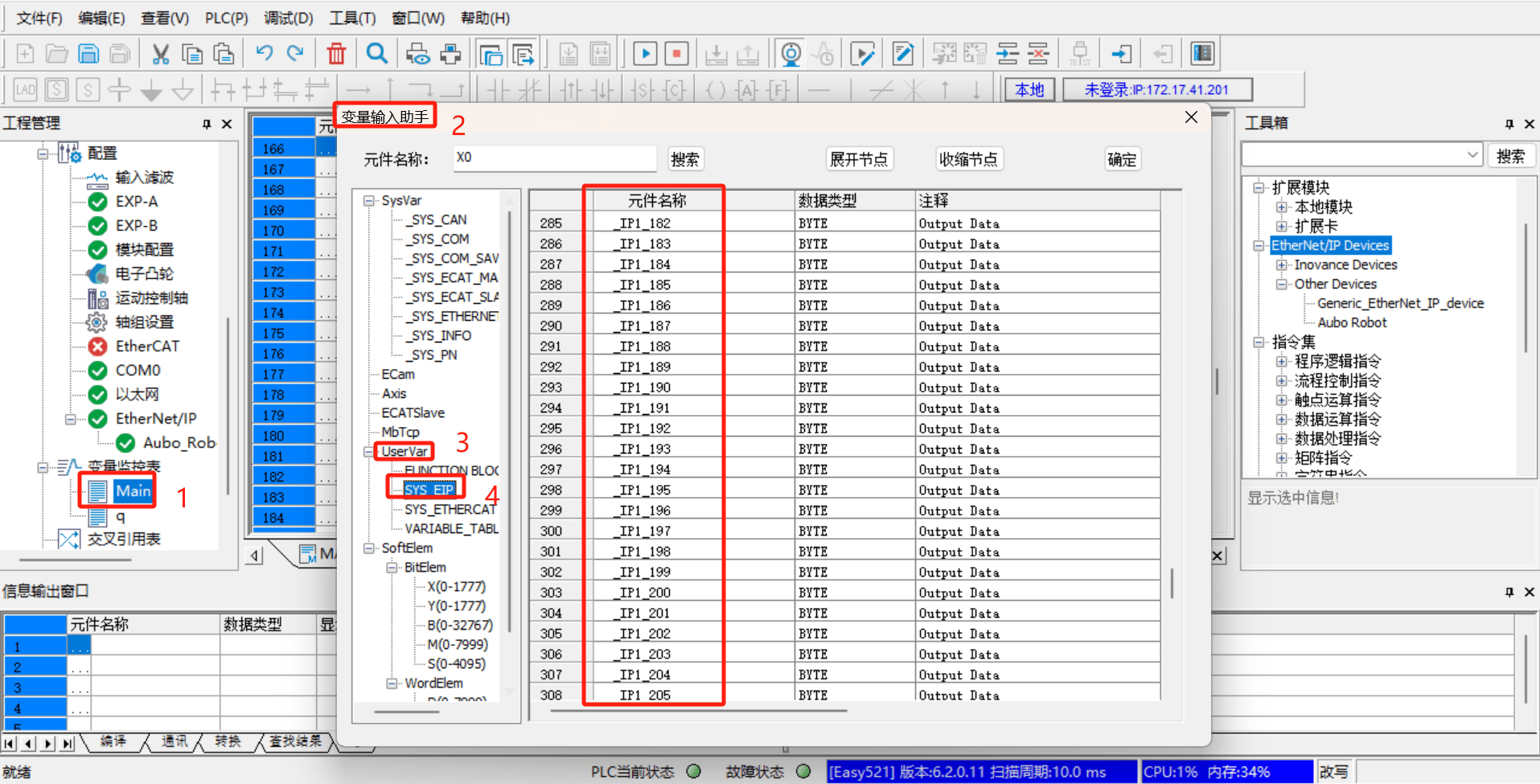
The addresses in SYS_EIP are imported according to the EDS file. The addresses inside are assigned in advance by the developers according to the EIP address table, and this address table corresponds to the EIP communication address table provided by the developers. You can select the corresponding address field according to the EIP address table;
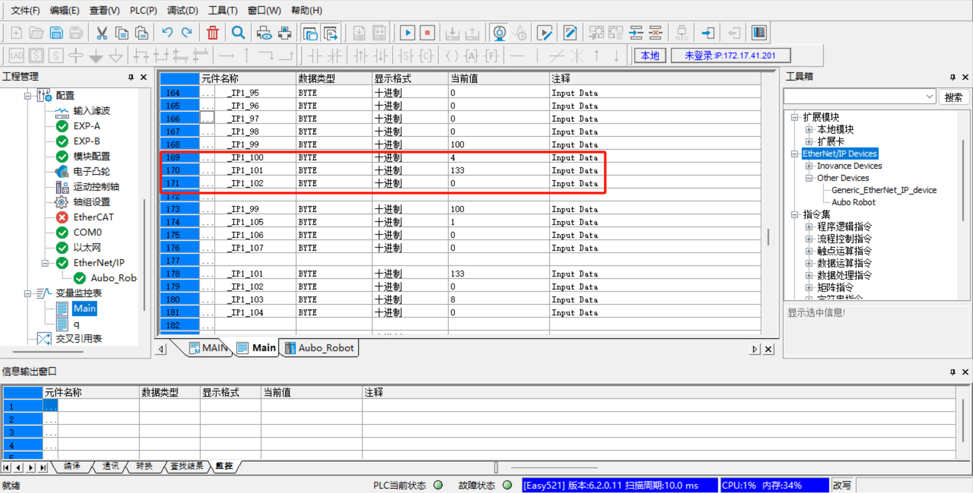
The following are some monitoring addresses added according to the EIP address table, including IO signals, position coordinates, joint angles, voltage, current, temperature, robot status, general-purpose coils (Robot => PLC), general-purpose registers (Robot => PLC), general-purpose coils (PLC => Robot), general-purpose registers (PLC => Robot), control project, and so on;
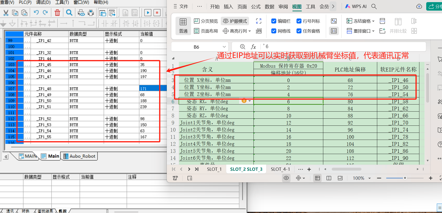
Being able to monitor signals from the EIP addresses indicates that the soft EIP communication is normal and can be used normally;
2.5 Common Problems and Solutions
- Failed to modify the PLC address
- Check whether the hardware wiring is correct, whether the network cable is loose, and whether the power cables of the switch and the PLC are loose;
- Connect the laptop and the PLC via
Type-C-to-USB and modify the PLC's IP address;
- Target device offline
Check the network cable connection and whether the PLC's IP setting is in the same network segment as the laptop;
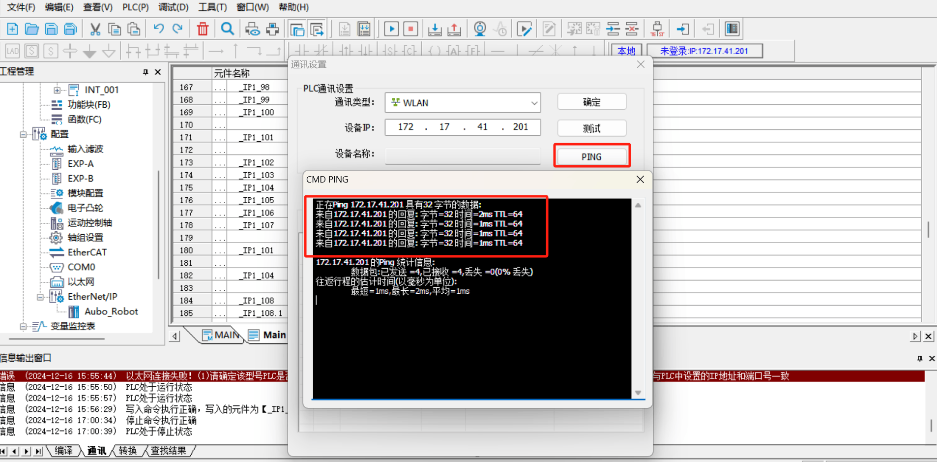
Use the PING tool to test whether the PLC and laptop network can
pingnormally;Restart
AutoShopand reconnect for testing;
- Cannot find the SYS_EIP address
The addresses in SYS_EIP are imported according to the EDS file. The addresses inside are assigned in advance by the developers according to the EIP address table. Follow the steps below;
(1)Under [EtherNet/IP], delete [Auto_Robot]; after deleting the EDS file, re-import it;
(2)Double-click to add [Auto_Robot], delete the original connection, and re-add the connection;
(3)Download to the PLC, click [Run] [Monitor], and check whether the SYS_EIP address can be found;
(4)If steps 2-4 do not resolve the issue, restart the control cabinet and the AutoShop software, and repeat steps 2-4;
- Communication succeeds but the read data is incorrect
The data does not change, but the result is incorrect: check whether the address in the variable monitor table is consistent with the EIP address table;
The data changes, but the result is incorrect: if the address is two bytes, all the data composed of the two bytes must be sent down (for example, the addresses of the end velocity and robot status are two bytes); if the acquired address is four bytes, all the data composed of the four bytes must be read (for example, position coordinates and joint angles are four bytes);
3 Detailed Profinet Migration Steps
3.1 Data Backup
Back up the ICM configuration file. Prepare a USB drive, navigate to the path "~/arcs_ws/config/", back up the ICM configuration file aubo_icm.conf, and copy this file out;
3.2 System Environment Check
Confirm the adapted software/firmware versions and the prototype/control cabinet type. Check whether the arcs version and control cabinet type currently in use support soft Profinet; if not, migration cannot be performed;
- The adapted arcs software versions include
0.28/0.29/0.31/0.32; - Except for the S and ES control cabinet types, which cannot be used, other control cabinets are supported;
- There is no firmware requirement;
3.3 Soft Profinet Installation and Configuration
3.3.1 Installing pn_server
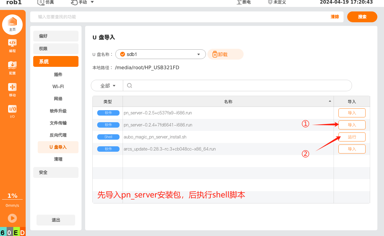
Use a USB drive to copy the required files, place the following files in the root directory of the USB drive, and then import them via the teach pendant, as shown in the figure below:
- pn_server-x.x.x.run
- aubo_magic_pn_server_install_v1.0_20240422.sh
3.3.2 Checking Whether Installation Succeeded
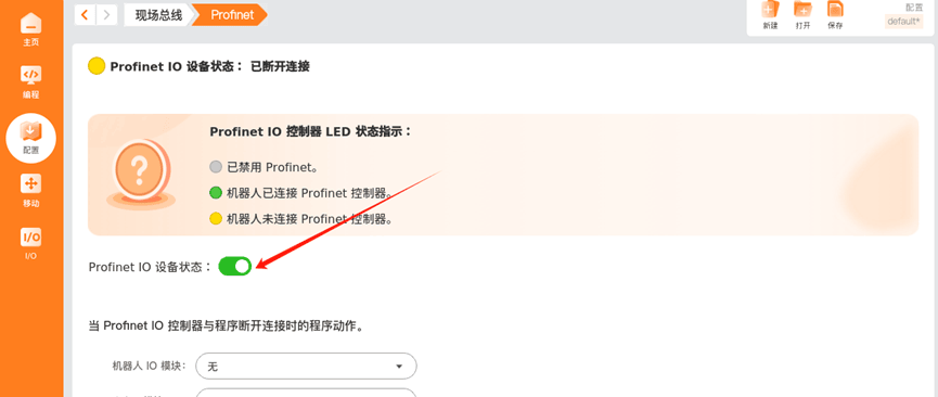
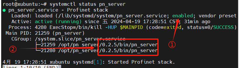
Use ARCS to turn on the Profinet button and observe the current state of Profinet IO; displaying Disconnected or Connected indicates a normal startup state.
Run systemctl status pn_server.service in the terminal to check:
①the current pn_server auto-start state (enabled indicates an auto-start process);
②confirm the current pn_server version;
3.4 Soft Profinet Test Verification
3.4.1 Opening the Profinet Slave
Click in sequence according to the following figure to open the profinet slave
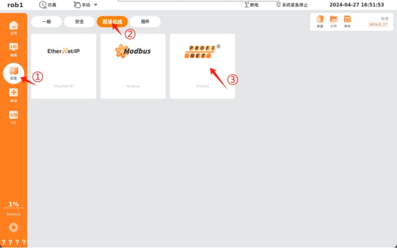
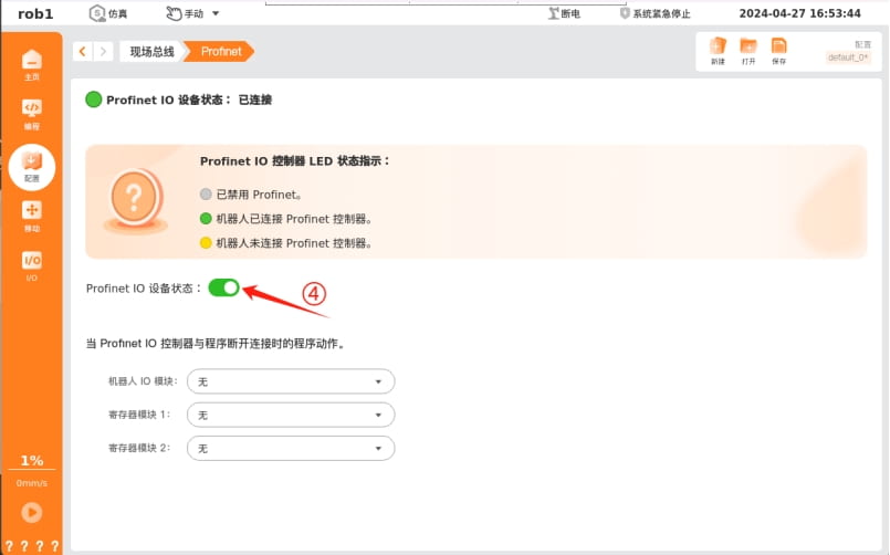
The figure below shows the correctly connected state; when not connected, the indicator light is yellow.
3.4.2 Connecting the PLC to the Profinet Slave
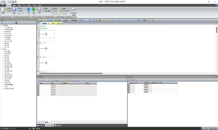
This tutorial uses the s7-200 smart plc as an example, hereinafter referred to as PLC
This PLC is programmed with the STEP-7 Micro/WIN SMART software, unlike the S7-1200 and similar, which use the TIA Portal software.
The software interface when opened is shown in the figure below
First, connect the computer and the PLC to the same local area network, and click in sequence according to the figure below to search for the PLC device on the local area network.
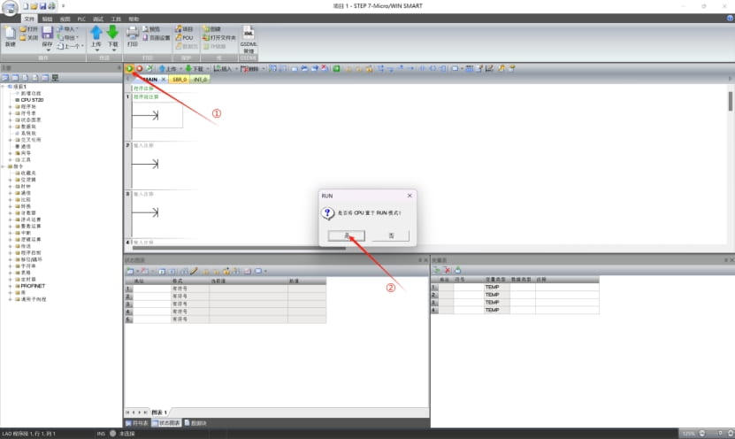
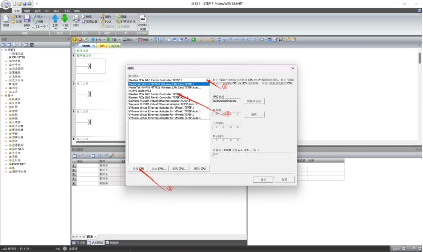
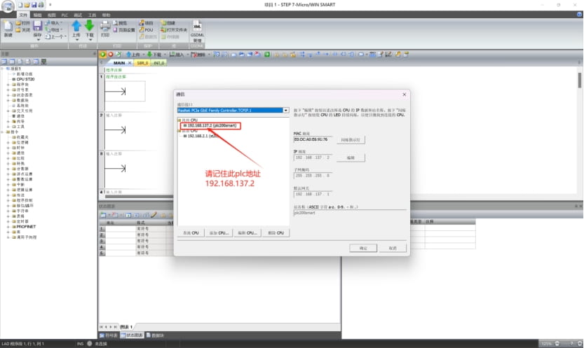
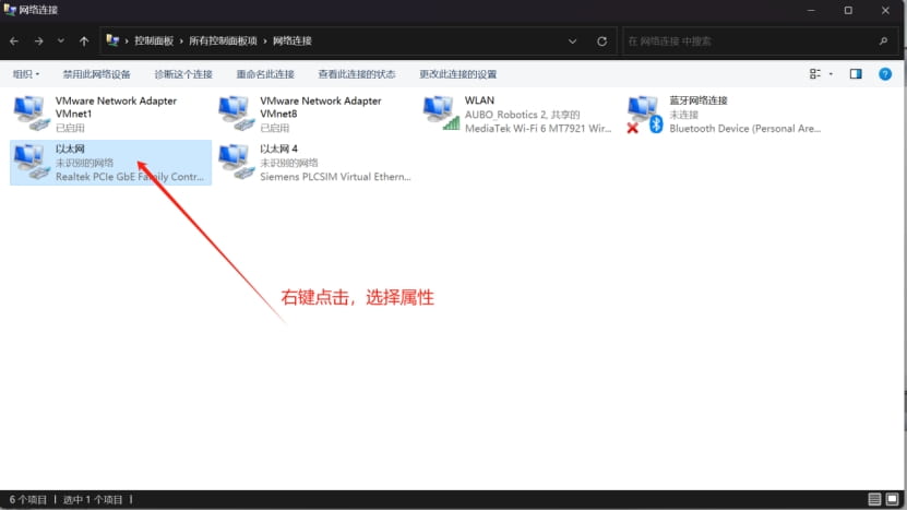
The PLC itself has an IP address; the computer needs to be configured with a fixed IP address on the same local area network in order to connect successfully. Taking this tutorial as an example, the PLC address is 192.168.137.2, and it is connected to the pcie network card (wired NIC). In this case, you need to configure the wired NIC's IP as 192.168.137.X, where X must be greater than 0 and less than 256, and must not duplicate any existing address. Next, configure the NIC's IP
WIN + R to open the Run window, type ncpa.cpl and press Enter to open the network connection settings
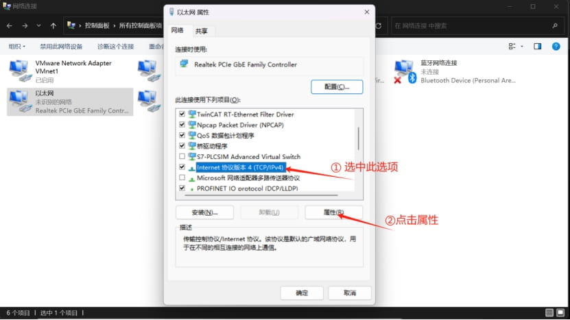
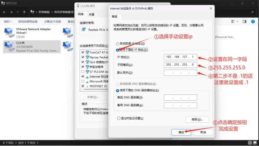
At this point, the PLC and the computer are in the same network segment, and a normal connection can be made.
Note: if you want to change the PLC address, you must be able to connect; if you want to connect to the PLC, it must be in the same network segment;
At this point, you can connect to the PLC normally.
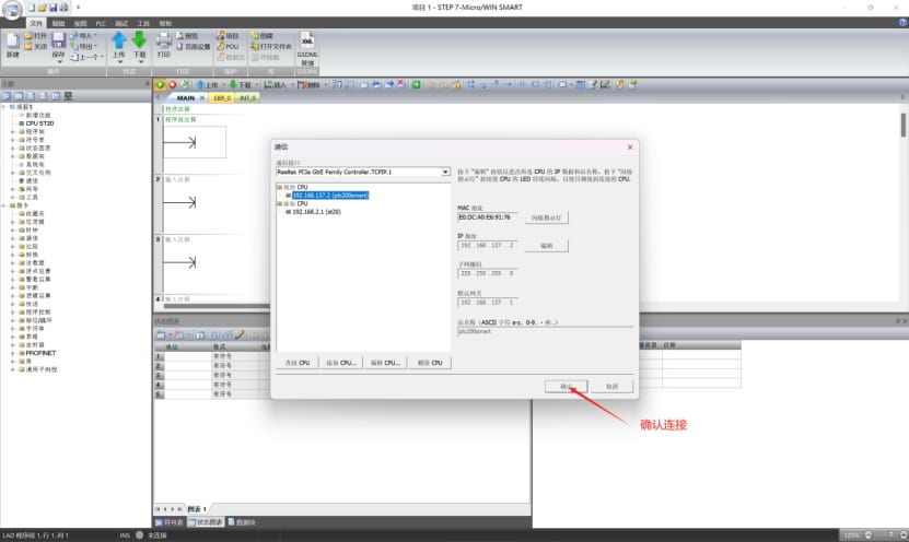
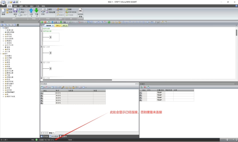
The state after connection is shown in the figure below
3.4.3 Configuring the Project
First, import the GSD file (device description file)
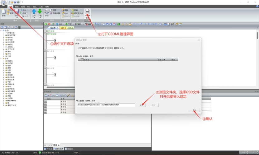
After the GSD file is imported successfully, next configure the Profinet test project.
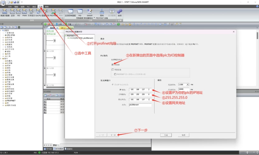
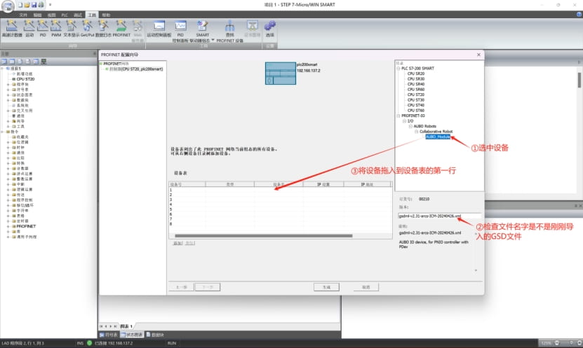
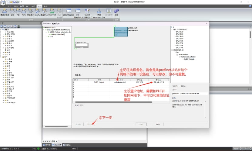
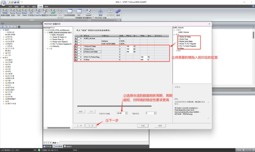
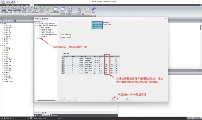
At this point, the Profinet configuration is complete. Save the project, click Download, and download this project to the PLC.
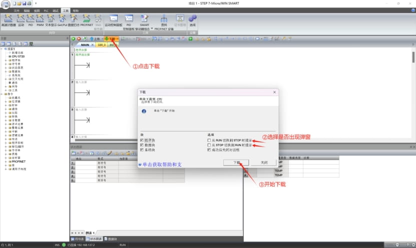
Now your PLC has completed the Profinet wizard and has been downloaded correctly; the robot's Profinet slave has been opened correctly, and the robot, PLC, and computer are on the same local area network and in the same network segment.
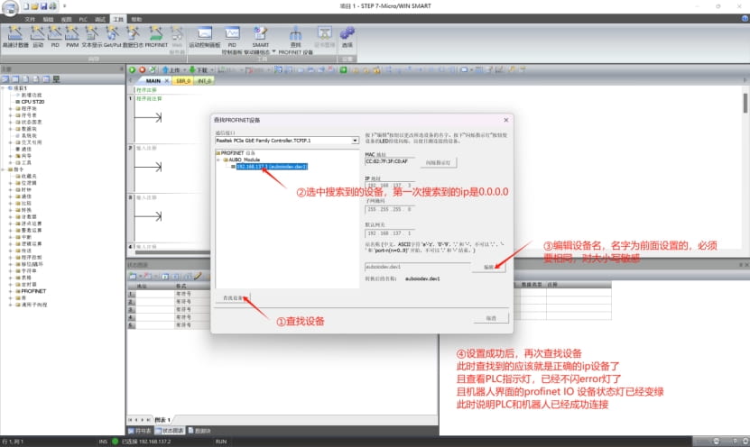
Search for Profinet devices on the local area network
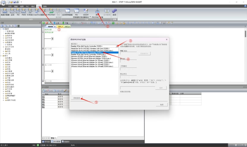
Then assign a name to the Profinet slave. At this point it is in the correctly connected state, as shown in the figure below.
3.4.4 Online Monitoring of Address Signals
This step is used to view the data of the robot slots.
Looking at the address table and the PLC's starting address, we can see that at address 190 of slot 2, two bytes, is the slave's heartbeat. We monitor this address for demonstration
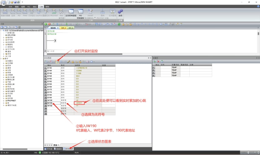
You can set other addresses yourself to monitor data changes. Being able to monitor signal changes indicates that the soft Profinet communication is normal and can be used normally.
3.5 Common Problems and Solutions
The following lists some causes and solutions for unsuccessful connections:
Confusing the robot IP and the profinet slave IP
Remember: the IP set on the teach pendant interface and the IP configured for profinet in the TIA Portal software must never be the same, otherwise connection failure or failure to connect to the external network may occur. You can modify the IP displayed on the teach pendant to another field in the same network segment.The configured slave name differs from the actual name
The slave name in the TIA Portal software needs to be unified with the configured name, and there must not be a slave with the same name in the same local area network.Upgrading the profinet plugin
After upgrading the profinet plugin, the slave name needs to be reassigned.Configuration file modification error
(1)In arcs version 0.28, the profinet switch button in the teach pendant is unavailable. To use the profinet plugin, set the enable_after_startup option in the configuration file to 1. For other versions, check whether the profinet switch is turned on.
(2)The network_port option in the configuration file is configured incorrectly; it defaults toenp1s0, with single quotes.
(3)The gsd_type in the configuration file is configured incorrectly. Initially only option 2 is supported, i.e., the address table compatible with the industrial gateway.GSD file not imported successfully
Please check whether the GSD file used is the one dedicated to the profinet plugin (the one included in the archive)For different control cabinets, the default network port needs to be modified
If unsure which network port is used, type: ifconfig in the control cabinet terminal, find the network port whose IP is the control cabinet's IP, and modify this network port into the/root/arcs_ws/config/pn_server.confconfiguration file. Turn profinet off and on again. For example, the improved control cabinet needs to change the default enp1s0 to enp2s0, the new C needs to be modified according to the actually plugged-in network port, and the iS control cabinet does not need to be changed.Analysis of abnormal situations in the STEP-7 Micro/WIN SMART software when the PLC (s7-200 smart plc) connects to the Profinet slave
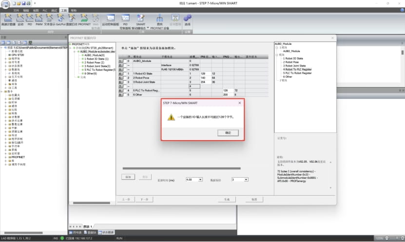
The popup window shown below indicates that the PLC memory is not large enough. Taking the figure below as an example, this PLC's input allows a maximum of 128 bytes of data, but slots 1 to 4 together exceed 128 bytes, so this popup window appears when dragging in slot 4, and slot 4 cannot be loaded correctly. The solution is to replace the PLC with one with better performance and configuration, or delete the unneeded slots and only load the required slots.