
Six-Axis Force Sensor Quick Configuration Guide
Scope of application: This guide applies to the installation, configuration, data reading, and troubleshooting of external six-axis force sensors. Depending on the robot arm control system type (AUBO PE system or ARCS system), the connection method and configuration method differ; please select the corresponding section for configuration based on your actual system type.
I. ARCS System Configuration
1 ARCS Preliminary Confirmation
Before installing the sensor, confirm the system version, hardware interface, and sensor model to avoid connection failure caused by compatibility issues.
1.1 System Version and Protocol Confirmation
The ARCS system natively supports CANLite protocol force sensors, with the following version requirements:
- ARCS system version ≥ v0.31.1
- If the version is lower, please upgrade the ARCS system first.
Note
The ARCS system only supports the CANLite protocol and does not support other protocols.
1.2 Hardware Interface Confirmation
Confirm whether the robot arm end has a communication interface:
- The end has an RS485 interface: connect the sensor directly through the end interface.
- The end has no corresponding interface: convert RS485 to USB and connect through the control cabinet's USB interface; the corresponding configuration must then be completed in the software.
1.3 Sensor Model Confirmation
Confirm that the sensor model is an officially supported model. For officially supported sensor models, see End Six-Axis Force Sensor User Manual, and check the latest compatibility list in the [Supported Sensor Models] section.
Note
If any of the above confirmation steps reveals an incompatibility, it is recommended to contact official after-sales support and uniformly update the hardware, software, and firmware to the latest versions.
2 ARCS Mechanical Installation
Check the robot arm end and the sensor surface for damage or foreign matter, and ensure that the mounting surface is flat and free of burrs.
The robot arm end is usually configured with two IO interfaces, of which the four-pin interface is the end RS485 communication interface. After the sensor is connected to the robot arm end, confirm that the fixing screws of the RS485 adapter are tightened in place and not loose, to avoid poor contact.
Note:
For detailed steps on force sensor installation, refer to Force Control Application Manual - Force Sensor Installation.
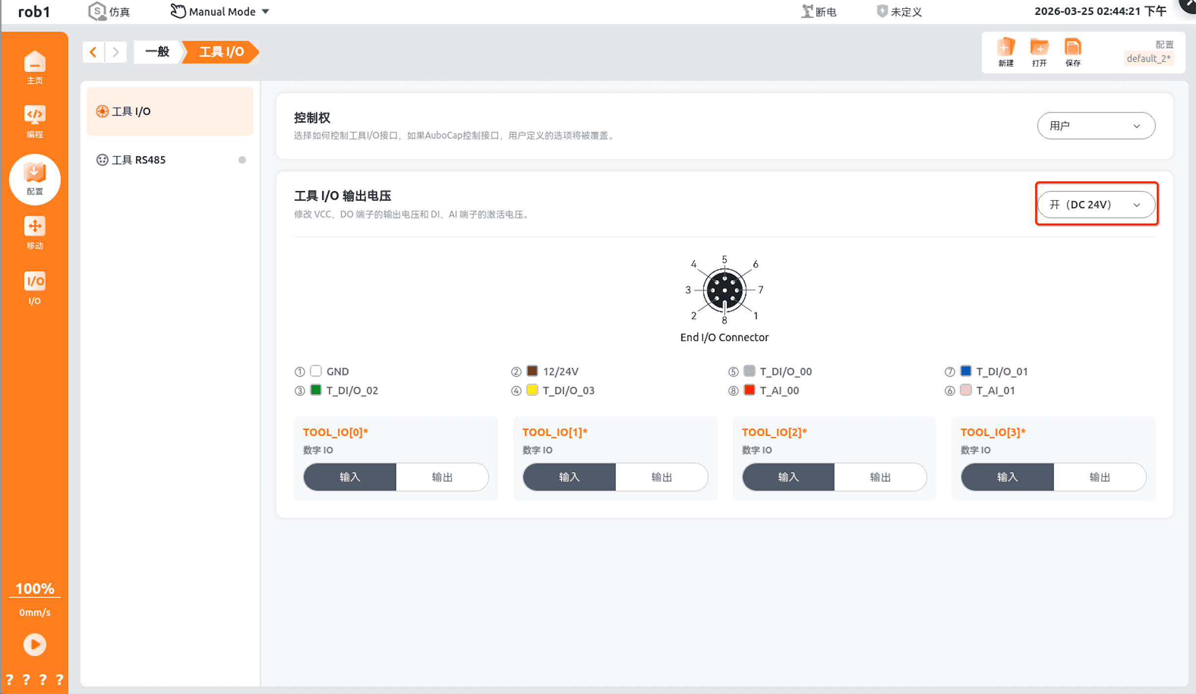
Sensor power supply: on the Tool I/O configuration page, set the output voltage of the VCC and DO terminals to DC24V:
3 API Function Description
Function 1: arcs::common_interface::RobotConfig::selectTcpForceSensor
- Function: initializes and selects the force sensor model.
- Parameters: name - the sensor model string; "KWTID60_300" here is only an example. You can first use the getTcpForceSensorNames interface to obtain all supported sensor models, then select a matching model and assign it to name.
- Function prototype: int arcs::common_interface::RobotConfig::selectTcpForceSensor(const std::string & name)
- Call example: selectTcpForceSensor("KWTID60_300") (called only once at program initialization)
- Python function prototype: selectTcpForceSensor(self: pyaubo_sdk.RobotConfig, arg0: str) -> int
- Lua function prototype: selectTcpForceSensor(name: string) -> nil
Function 2: arcs::common_interface::RobotState::getTcpForceSensors
- Function: reads sensor data.
- Function prototype: int arcs::common_interface::RobotState::getTcpForceSensors()
- Python function prototype: getTcpForceSensors(self: pyaubo_sdk.RobotState) -> List[float]
- Lua function prototype: getTcpForceSensors()-> table
4 ARCS Configuration and Usage Flow
The ARCS system natively supports CANLite protocol force sensors. The configuration and usage flow is as follows:
- Confirm that the ARCS system version is ≥ v0.31.1 (if the version is too low, upgrade the system first).
- Complete the sensor mechanical installation.
- Complete the 24V power supply configuration on the Tool I/O configuration page and confirm that the sensor communicates normally (sensor online).
- Call the initialization API to select the sensor model (see the "3 API Function Description" section for details).
- The sensor can be used after calibration is completed.
For sensor deployment and debugging steps, refer to End Six-Axis Force Sensor User Manual.
5 Force Control Documentation Summary
- End Six-Axis Force Sensor User Manual
- Force Control User Manual
- Force Control Plugin User Manual
- Force Control Application Implementation Plan
II. AUBO PE System Configuration
1 AUBO PE Preliminary Confirmation
Before installing the sensor, confirm the plugin version, hardware interface, and sensor model to avoid connection failure caused by compatibility issues.
1.1 Plugin Version Confirmation
The AUBO PE system supports six-axis force sensors through a dedicated adapter plugin, with the following version requirements:
- Latest plugin version v2.0.12
- If the version is lower, please install the latest official adapter plugin.
Note
The AUBO PE system does not directly support the CANLite protocol; the force sensor function must be implemented through the official adapter plugin.
1.2 Hardware Interface Confirmation
Confirm whether the robot arm end has a communication interface:
- The end has an RS485 interface: connect the sensor directly through the end interface.
- The end has no corresponding interface: convert RS485 to USB and connect through the control cabinet's USB interface; the corresponding configuration must then be completed in the software.
1.3 Sensor Model Confirmation
Confirm that the sensor model is an officially supported model. Currently supported sensor types include Kunwei, Yuli, Xinjingcheng, OnRobot, ATI, and Wacoh sensors, and the communication methods support both TCP and SerialPort.
Note
If any of the above confirmation steps reveals an incompatibility, it is recommended to contact official after-sales support and uniformly update the hardware, software, and firmware to the latest versions.
2 AUBO PE Mechanical Installation
- Check the robot arm end and the sensor surface for damage or foreign matter, and ensure that the mounting surface is flat and free of burrs.
- The robot arm end is usually configured with two IO interfaces, of which the four-pin interface is the end RS485 communication interface. After the sensor is connected to the robot arm end, confirm that the fixing screws of the RS485 adapter are tightened in place and not loose, to avoid poor contact.
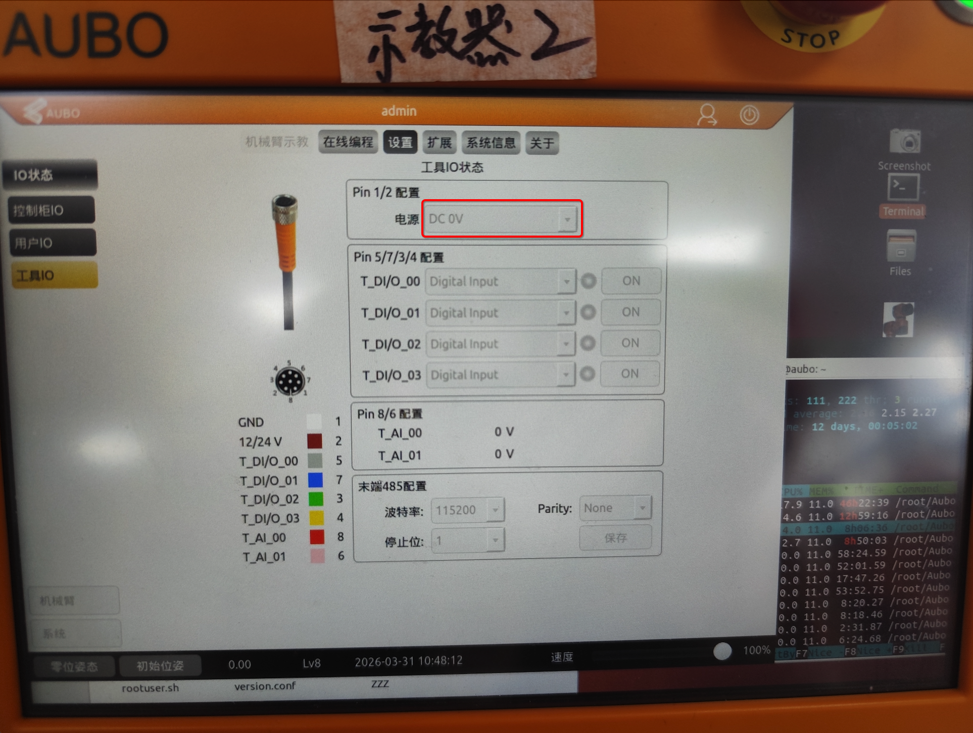
- Sensor power supply: on the Tool I/O configuration page, set the power supply voltage to DC24V. Note that the baud rate of the end 485 must be consistent with the sensor's baud rate; for the baud rates of each sensor model, see the appendix section of the Force Sensor Plugin User Manual.
3 AUBO PE Configuration and Usage Flow
The AUBO PE system supports six-axis force sensors through a dedicated adapter plugin. The configuration and usage flow is as follows:
- Install the dedicated adapter plugin for the six-axis force sensor (plugin version ≥ v2.0.12, subject to the latest official version).
- Complete the sensor mechanical installation.
- Complete the 24V power supply configuration on the Tool I/O configuration page and confirm that the sensor communicates normally (sensor online).
- Select the sensor type on the plugin's registration interface.
- The sensor can be used after calibration is completed.
For sensor deployment and debugging steps, refer to: Force Sensor Plugin User Manual
III. Troubleshooting Guide
| Fault symptom | Possible cause | Troubleshooting steps and solutions |
|---|---|---|
| Communication failed, sensor offline, data not updating | 1. 24V power supply not connected or abnormal voltage 2. RS-485 wiring order (A/B) reversed 3. Communication line broken | 1. Check the 24V power indicator (if any) or measure the voltage between V+ and GND 2. Swap the A and B wiring and test 3. Check whether the wiring terminals are loose and whether the cable is intact |
| Data drift exceeds the normal range, zero point unstable | 1. Excessive ambient temperature change, sensor not fully warmed up; 2. Mounting stress present, sensor not fixed perpendicularly; 3. Sensor zero point calibration not completed | 1. Place the sensor in a stable temperature environment and evaluate data stability after operating for 30 minutes; 2. Reinstall the sensor to ensure coaxiality and eliminate mounting stress; 3. Complete the sensor zero point calibration on the "Configuration" > "General" > "Tool I/O" page. |
| Force control cannot be enabled (ARCS system) | 1. ARCS system version too low, not a natively supported version; 2. Sensor is not an officially supported model | 1. Upgrade the ARCS system to v0.31.1 or later; 2. Confirm that the sensor model is in the official supported list, and replace non-supported models with compatible models |
| Force control cannot be enabled (AUBO PE system) | 1. Adapter plugin not installed / plugin version incompatible; 2. Sensor is not an officially supported model | 1. Install the latest official adapter plugin; 2. Confirm that the sensor model is in the official supported list, and replace non-supported models with compatible models |
If you encounter problems that cannot be resolved during sensor selection, installation, configuration, or use, it is recommended to contact after-sales support for technical assistance. When contacting after-sales support, provide the system version, sensor model, fault symptom, and connection method to help quickly locate the problem.