
Modbus RTU Serial Communication Test
1 Preparation
Two USB-to-RS485 serial cables, two DuPont wires, XCOM software, MobaXterm software, and MODSIM software.
XCOM software download link: https://download.aubo-robotics.cn/3rd-party/XCOM_V2.3.zip
MobaXterm software documentation: 34 Using MobaXterm to Remotely Manage the Target Device · GitBook (aubo-robotics.cn)
MODSIM software download link: Modscan32+Mosim32_SN_TCP Debugging Tool
2 Operation Steps for Testing Serial Communication
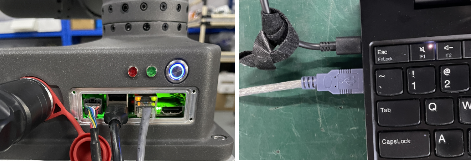
- Connect the two 9-pin USB-to-RS485 serial cables together using DuPont wires. The wiring method is pin 1 to pin 1 and pin 2 to pin 2, as shown in the following figure.

- Connect the two USB connectors to the computer and the control cabinet respectively.
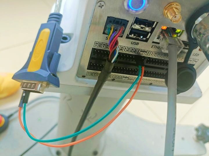
- You can also connect one 9-pin USB-to-RS485 serial cable directly to the control cabinet using DuPont wires: connect pin 1 to RS485+ and pin 2 to RS485-, as shown in the figure.
- The 485 silkscreen labels and serial port numbers displayed in the software for each control cabinet model are shown in the table.
| Controller 485 | Interface Board 485 | IS | Improved Control Cabinet | New C | S/ES3/ES5 | Mini Control Box | |
|---|---|---|---|---|---|---|---|
| 485 IO Silkscreen | 485_A, 485_B | None | A2, B2 | None | None | ||
| Mapped Port Number | ttyIfaceBrd | None | ttyIfaceBrd | None | None | ||
| UI Display | [I/O] 485_A, 485_B | None | [I/O] A2, B2 | None | None | ||
| Native 485 | 485 IO Silkscreen | RS485 | Modbus RTU | A1 B1 | 485+ 485- | COM2 | |
| Port Number | ttyS2 | ttyS2 | ttyS0 | ttyS7 | ttyS2 | ||
| UI Display | RS485 | Modbus RTU | [I/O] A1, B1 | [I/O] 485+, 485- | COM2 |
| Extended 485 | Tool RS485 | Port Number | ttyRobotTool |
| UI Display | Tool RS485 Tool RS485 | ||
| USB-RS485 | Port Number | ttyUSB* - Example: ttyUSBxx | |
| UI Display | USB-RS485 (xx) - xx is the xx in ttyUSBxx |
- Open MobaXterm and enter the command
dmesg|grep usbin the control cabinet terminal to check whether thettyUSB*port on the control cabinet has recognized the USB serial cable device.
dmesg|grep usb
This indicates that the USB device has been successfully recognized. It is a full-speed USB device with number 3, and the device name is FT232R USB UART.

This indicates that the USB-to-485 serial cable has been connected to the ttyUSB0 port.
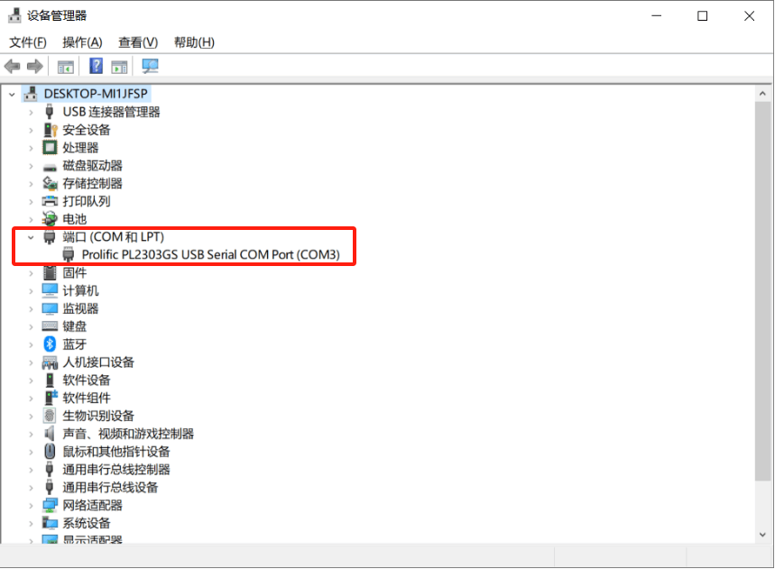
- On the computer, open Device Manager and check the port number. As shown in the following figure, the port number recognized on the computer is COM3.
- Open the control cabinet terminal and set the serial port baud rate, data bits, parity, and stop bits.
stty -F /dev/ttyUSB0 115200 cs8 -parenb -cstopb- /dev/ttyUSB0 indicates the path of the
ttyUSB0serial device file - 115200 indicates the baud rate value
- cs8 indicates 8 data bits
- -parenb indicates no parity bit
- -cstopb indicates 1 stop bit
- Open the control cabinet terminal and query the serial port parameters.
stty -F /dev/ttyUSB0 -a
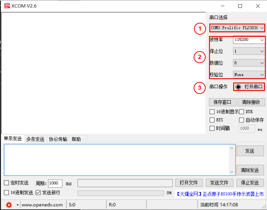
- Open XCOM software on the computer, select the serial port number, set the baud rate, stop bits, data bits, and parity bit, and click
Open Serial Port.
- In the control cabinet terminal, use
echoto send data to the serial port. The XCOM software on the computer will print the received data.
echo "test" > /dev/ttyUSB0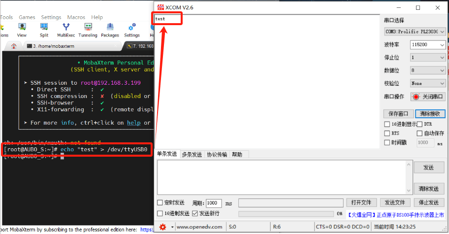
- In the control cabinet terminal, use
catto read data from the serial port.
cat /dev/ttyUSB0Open XCOM software, enter data, and click Send.
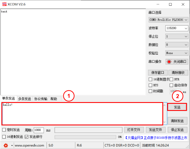
The control cabinet terminal will print the received data.

3 Operation Steps for Modbus RTU Communication
Connect the computer and the control cabinet using a USB-to-RS485 adapter cable.
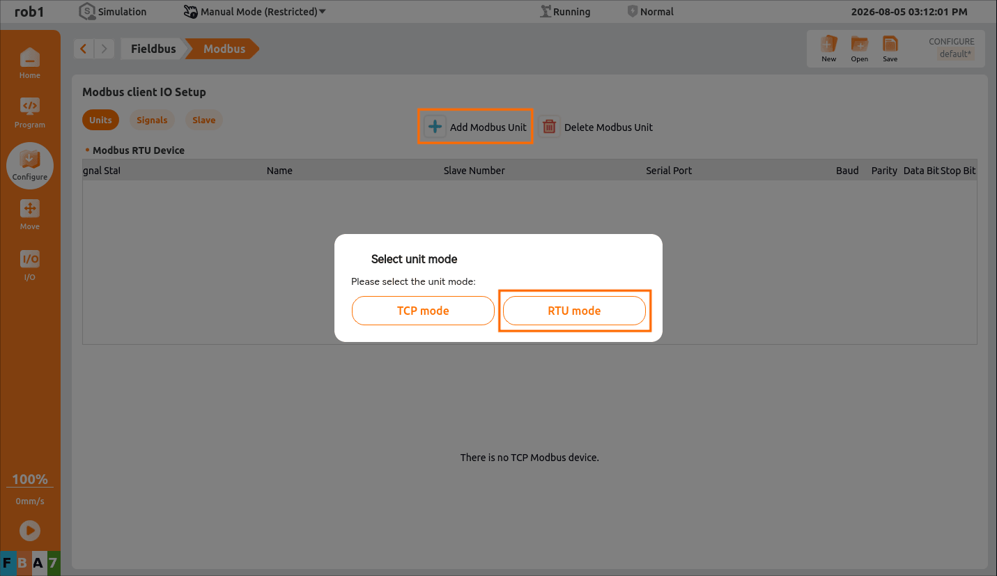
On the teach pendant's
Configuration - Fieldbus - Modbusscreen, clickAdd Modbus Unit, selectRTU Mode, and create a new Modbus RTU device.
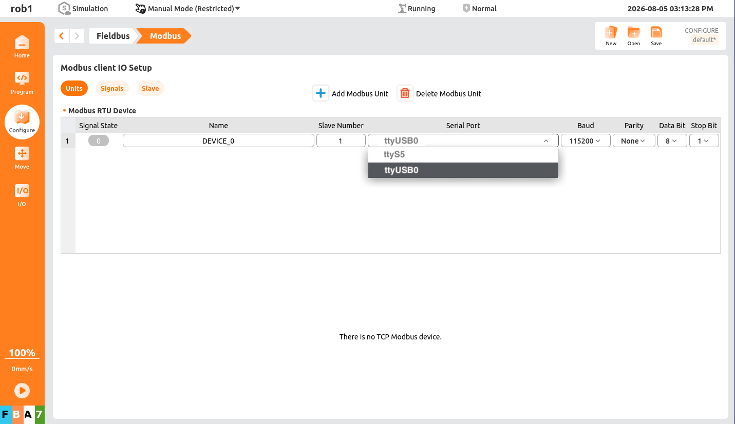
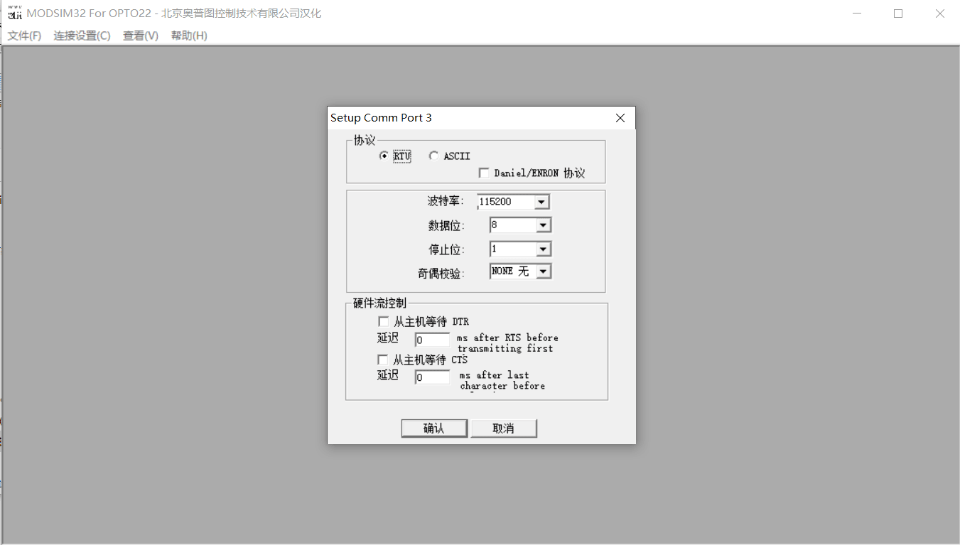
- Set the serial port number, baud rate, parity, data bits, and stop bits.
- Open MODSIM software and connect the port number.
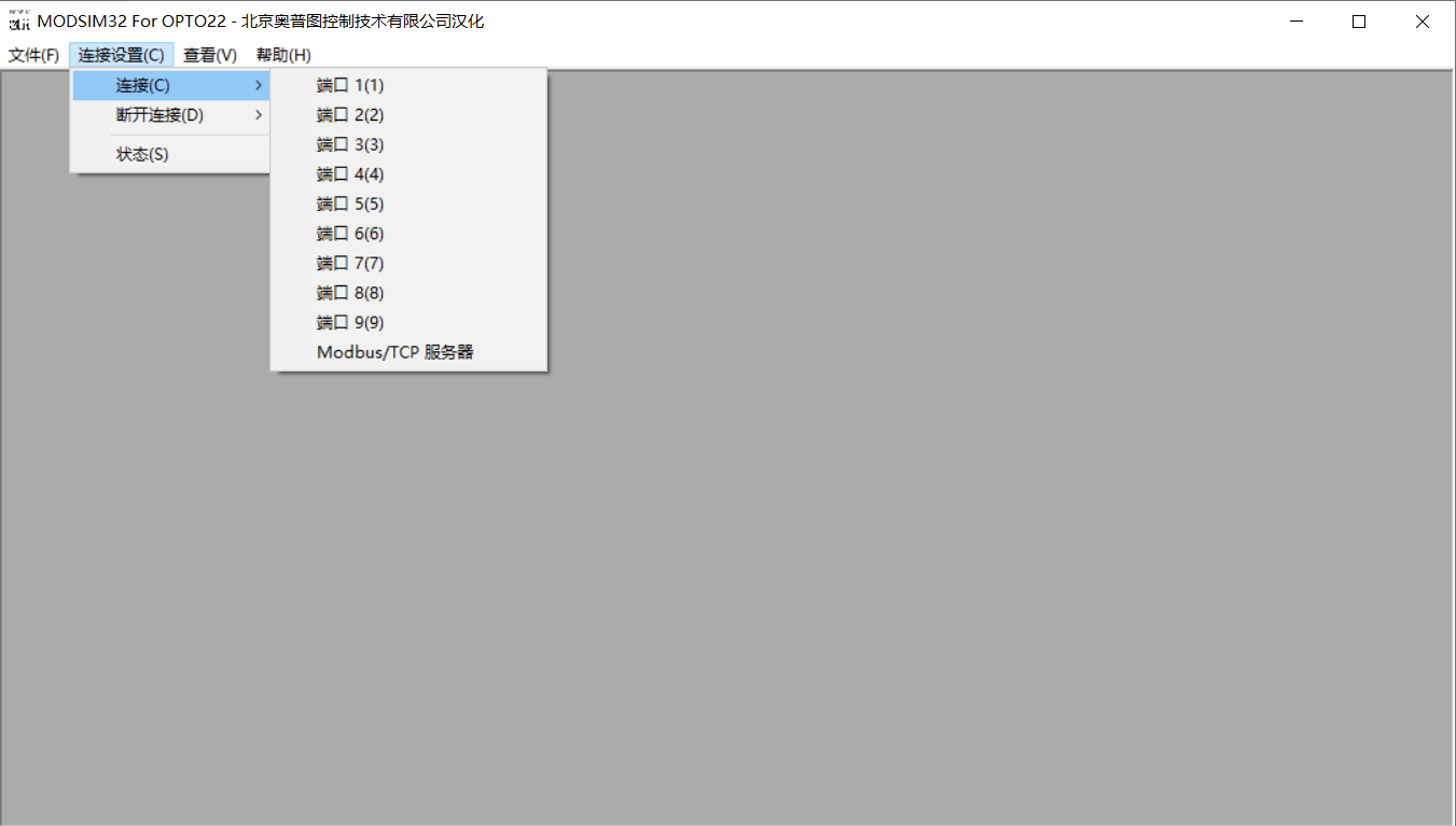
- Set the baud rate, parity, data bits, and stop bits, and click
OK.
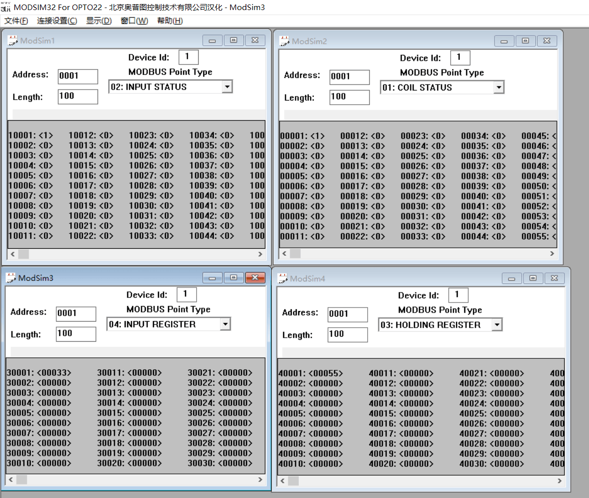
- Create Modbus signals in the teach pendant and MODSIM respectively. In MODSIM software, modify the signal type and address so that they correspond to the Modbus signals on the tablet.
The signal types in MODSIM include the following four types:
- INPUT STATUS indicates digital input
- COIL STATUS indicates digital output
- INPUT REGISTER indicates register input
- HOLDING REGISTER indicates register output
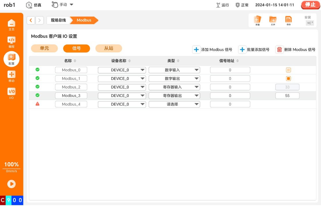
A green check mark icon indicates successful communication, and a red exclamation mark icon indicates unsuccessful communication.