Profinet Slave - Transferring Floats
Profinet does not natively support floats, but some users have a need to transfer floats, so in the current version two 16-bit registers can only be combined into a float. This application is mainly used in teach pendant programming.
The math library has two functions, one for converting uint16 to float and one for converting float to uint16
out_float = math.words2float(in_low,in_high)
out_words = math.float2words(in_float)
Note: When the PLC's registers store a float, the high word comes first and the low word comes last. The float conversion functions in the math library put the low word first and the high word last.
Preset Scenario:
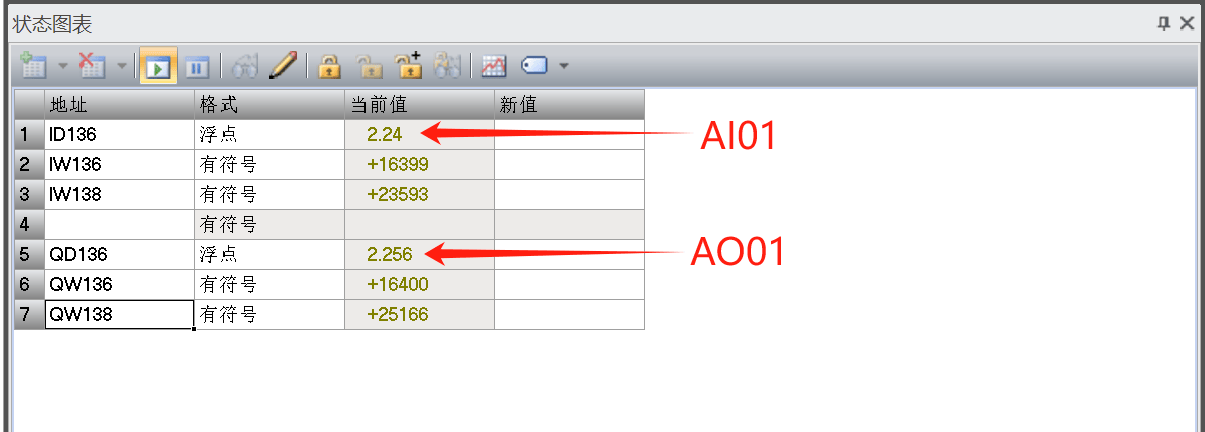
The PLC sends the analog output of AO01 at 2.256 volts to the robot, and at the same time reads the analog input of AI01 (for the convenience of testing, in the hardware wiring the output of AO01 is connected to the input of AI01, that is, whatever value the PLC sends is the value the PLC receives, and AO01 outputs an equivalent voltage).
Based on the above preset scenario, first define the register functions. What needs to be exchanged here is a float, and the ARCS Profinet slave address table does not yet support floats, so two 16-bit registers are used here to store one float. According to the Profinet slave address table, slot 4 and slot 5 are the registers for interaction between the robot and the PLC, and the 16-bit registers all start from an 8-byte offset (bytes 0–7 are bool registers).
PLC Setup:
Use the four addresses 8, 9, 10, and 11 of slot 4 for receiving data returned from the robot; the corresponding robot registers are int16Register[32] and int16Register[33]. Use the four addresses 8, 9, 10, and 11 of slot 5 for sending data to the robot; the corresponding robot registers are int16Register[0] and int16Register[1]. (Here the first 32 bits of the robot's 64-bit registers are used for slot 5, that is, PLC-to-robot; the last 32 bits are used for slot 4, that is, robot-to-PLC.)
The PLC used here is the S7-200 SMART, and the host software is STEP 7-Micro/WIN SMART. The address assignment for slot 4 and slot 5 of the PLC slave is as follows
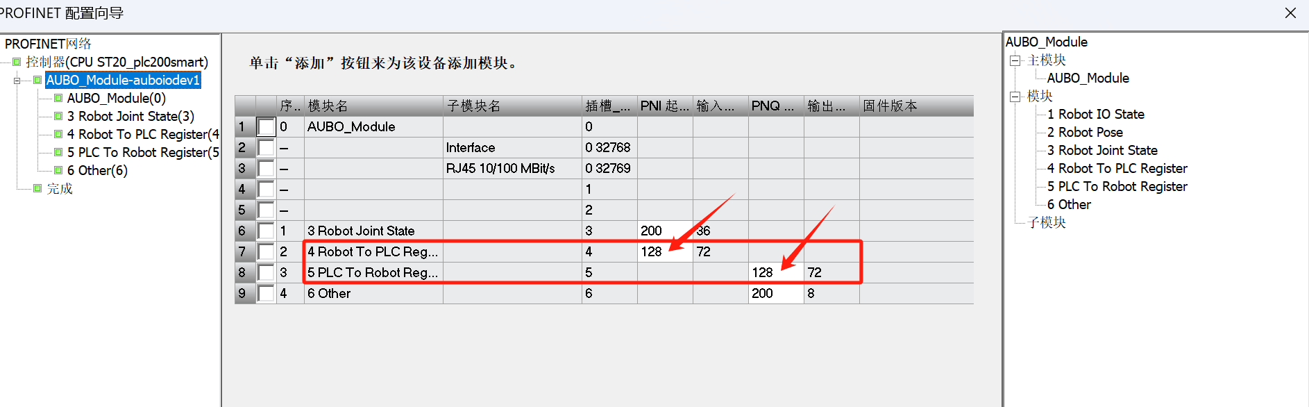
That is, QD136 is the address on the PLC side for sending to the robot, and ID136 is the address on the PLC side for receiving from the robot. Here the PLC side simply uses the monitoring table to send and receive data.
Robot Teach Pendant Programming:
The robot side needs to receive the data of int16Register[0] and int16Register[1], convert them into a float and set it into AO01; then read the value of AI01, split it into uint16 and set it into int16Register[32] and int16Register[33], and automatically send it to the PLC through Profinet communication.
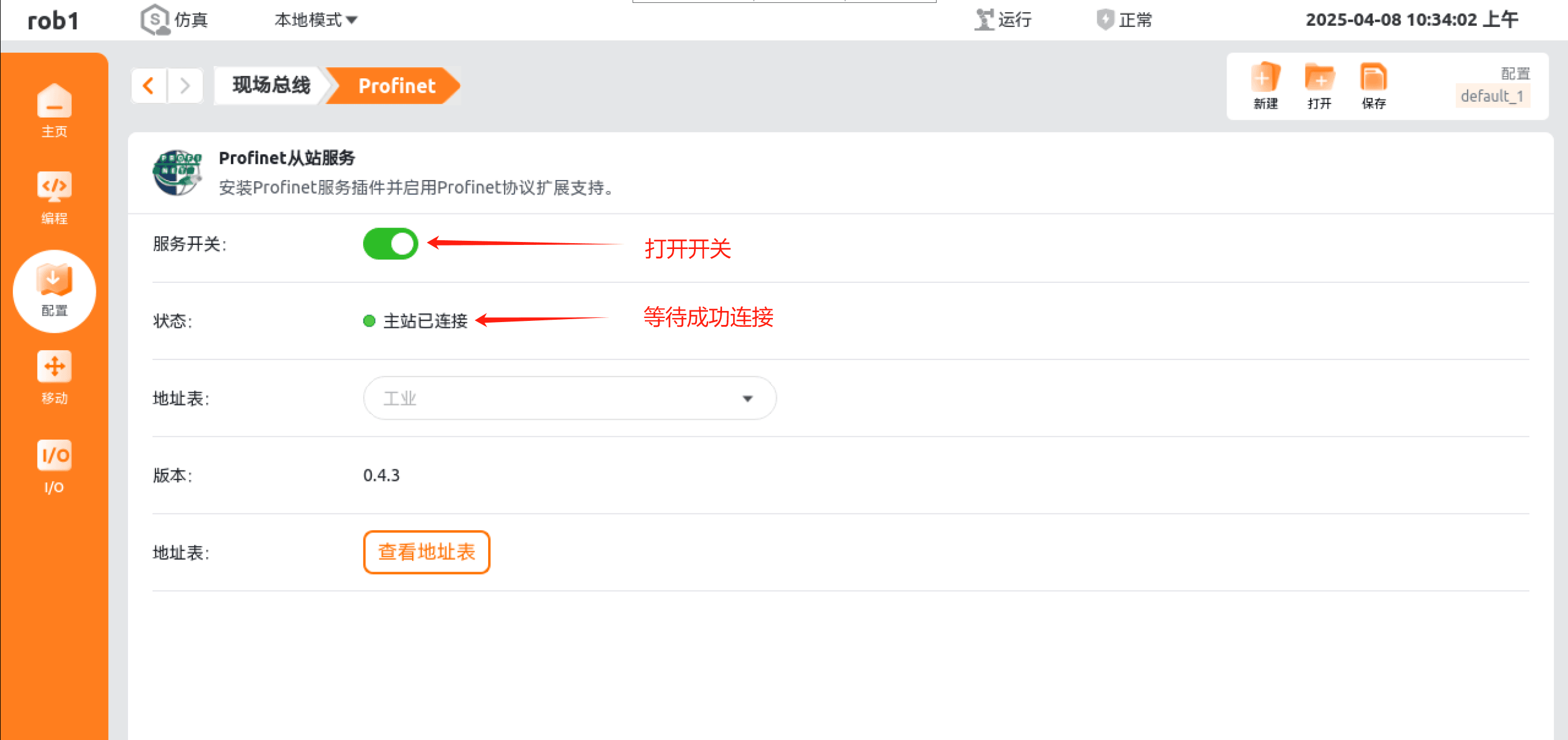
First open the robot Profinet slave, then program in the teach pendant, and finally run the program.
The teach pendant program is as follows program.zip
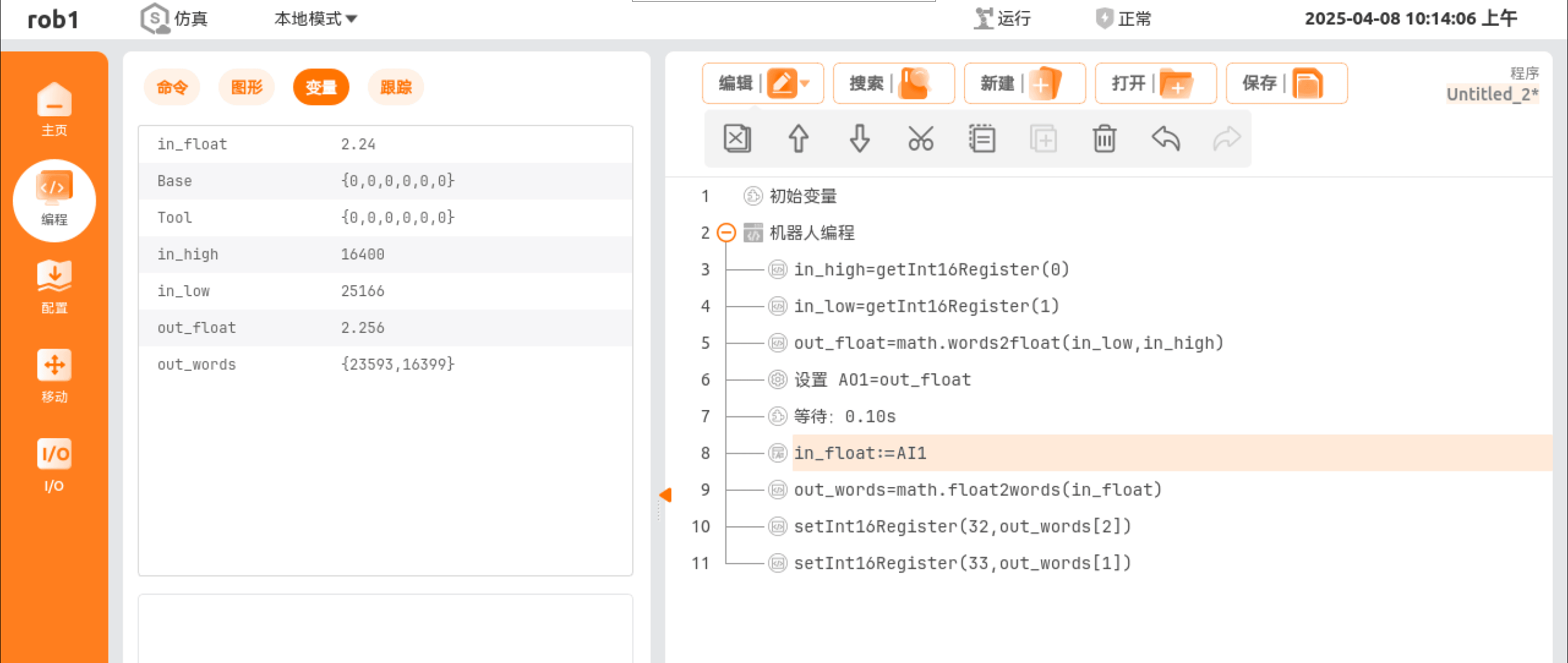
Note: the float conversion functions both put the low word first, which is the reverse of the PLC. Therefore the input and output parameters are both low-word-first. Please pay attention when using them.
Test Results:
Because the hardware wiring connects AO01 directly to AI01, the expected phenomenon is that the value of ID136 is essentially the same as the value set in QD136.
The actual test results are as follows: