Sensor Debugging Tool User Manual
1. Feature Introduction
The ARCS Sensor Debugging Tool is a graphical sensor debugging tool newly designed and developed in branch 0.31.1 and above. By establishing communication with your hardware device (sensor), it enables real-time acquisition, visual display, and data analysis or recording of various directional data, and supports online parameter configuration, greatly improving work efficiency and troubleshooting capability.
- Intuitive visualization: Converts serial port data into real-time curves, clear at a glance.
- In-depth analysis: Complete data acquisition functionality helps you precisely locate intermittent problems.
- All-in-one tool: The tool is integrated into the ARCS software, with no need to import plugins.
2. Sensor Debugging Tool Feature Display and Layout
The figure below shows the main interface layout of the sensor debugging tool and marks each core functional area:
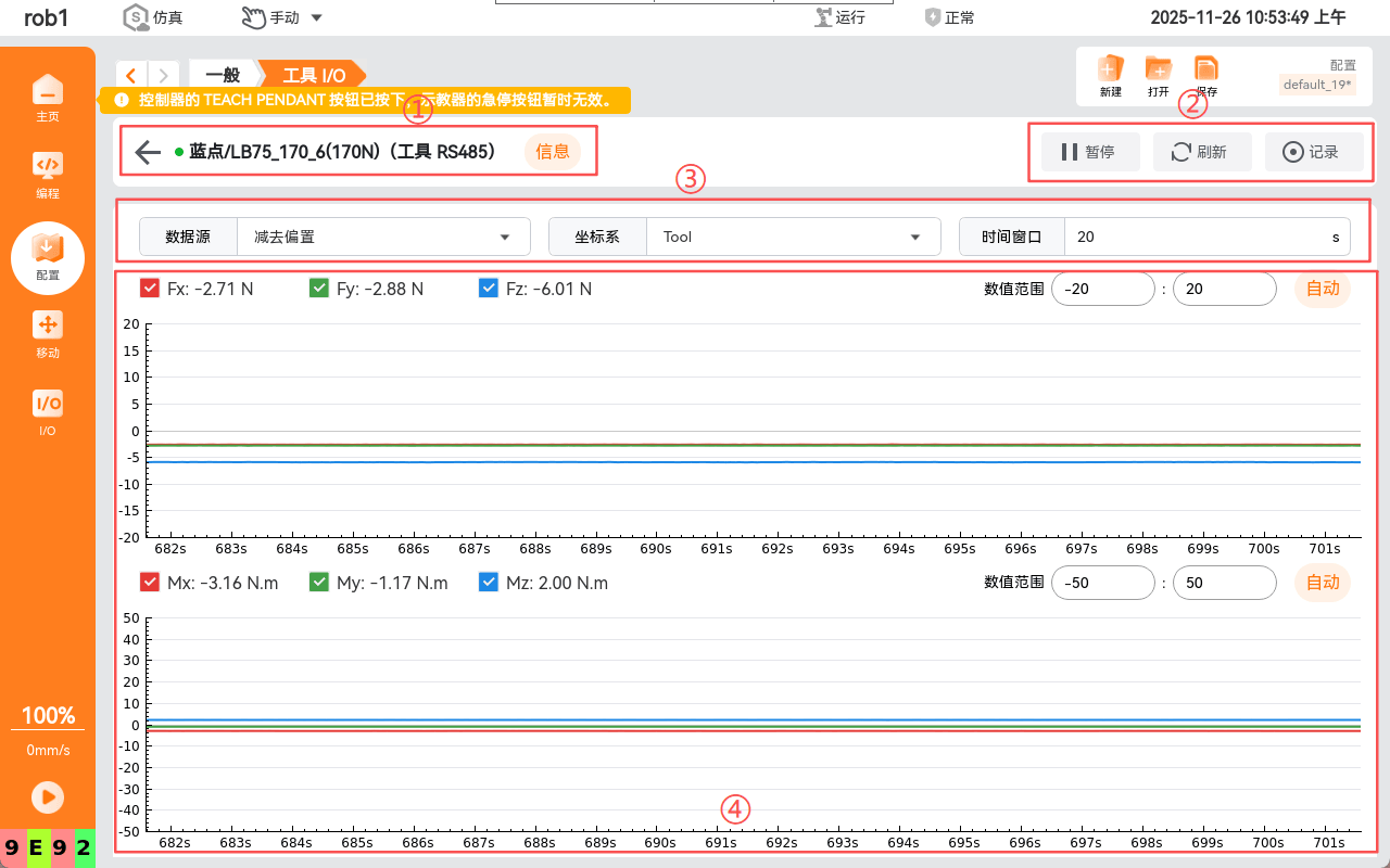
The main interface is mainly divided into the following four areas:
- Sensor status and information bar
- Data interaction area
- Parameter configuration area
- Real-time data display area
3. Detailed Introduction to the Functional Areas
- Sensor status and information bar
- Function description: Displays the sensor's basic information, including brand, model, and range; the bubble shows more details.
- Main controls:
- Info: Displays the sensor information in detail.
- Data interaction area
- Function description: Sends control commands for device data.
- Main controls and operations:
- Pause: Pauses the currently playing data.
- Refresh: Clears the currently playing data, then starts recording again.
- Record: Starts recording data from the current point; files are stored at /root/arcs_ws/force_control_sensor.
- Parameter configuration area
- Function description: Modifies the device's data parameters online without modifying the device itself.
- Main controls and operations:
- Data source: The sensor contains offset data; you can use the dropdown to select raw data or subtract the offset.
- Coordinate system: The reference coordinate system for sensor data.
- Time window: Sets the range of the curve data.
- Real-time data display area
- Function description: Displays sensor data in real time in graphical and numerical form; it is the core of this tool.
- Main controls and operations:
- Checkbox buttons: Control the show/hide state of single-direction data, supporting showing only some axis curves (real-time data keeps refreshing).
4. Activating an External Sensor
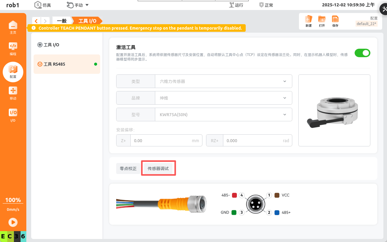
Connect a six-axis force sensor to the robot arm, open "Configuration > Tool I/O > Tool RS485" in the software, and use the dropdown to select the corresponding sensor brand and range.
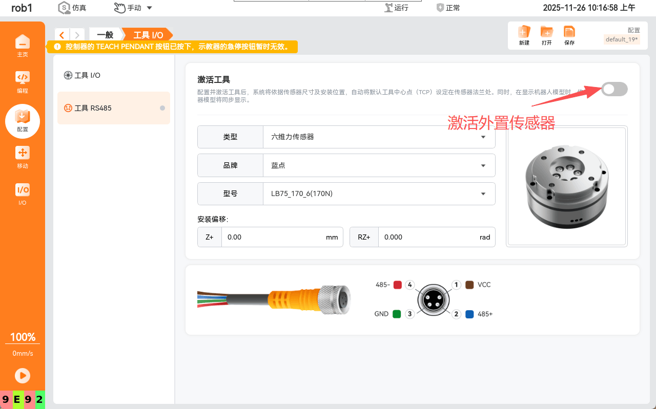
Activate the current sensor device to display the debug button; click the button to enter the sensor debugging interface.