
Visual Positioning User Guide
I. Feature Overview
The visual positioning feature relies on the vision node and provides a zero-code configuration Socket communication solution. Users can complete the entire configuration process through the graphical interface; the system automatically generates the underlying Socket script, so there is no need to write or touch any code.
System Architecture
Node trigger (camera configuration) > backend driver > socket communication > vision system > image acquisition and processing > output results > programming application.
Core Components
- Vision node: the selection of camera configuration and the trigger recognition process.
- Camera configuration module: camera communication parameter management.
- Communication driver: task execution logic control.
II. Camera Configuration
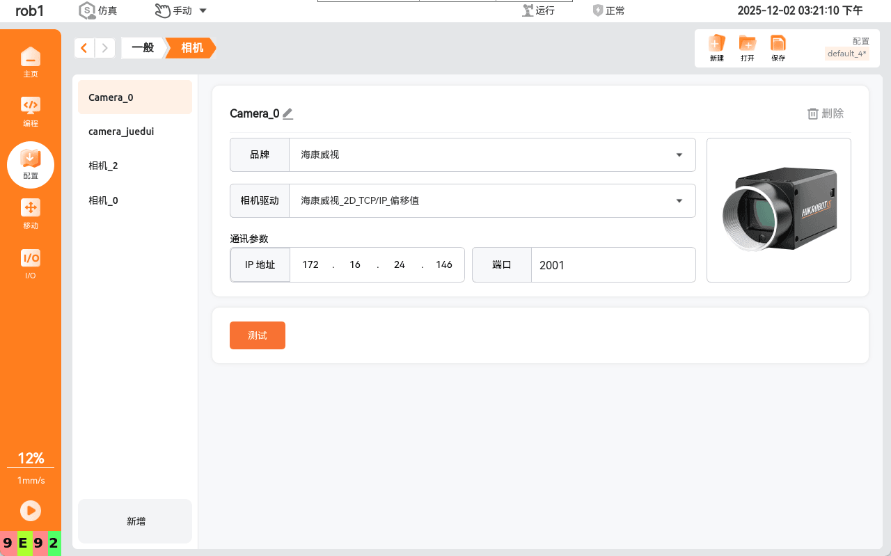
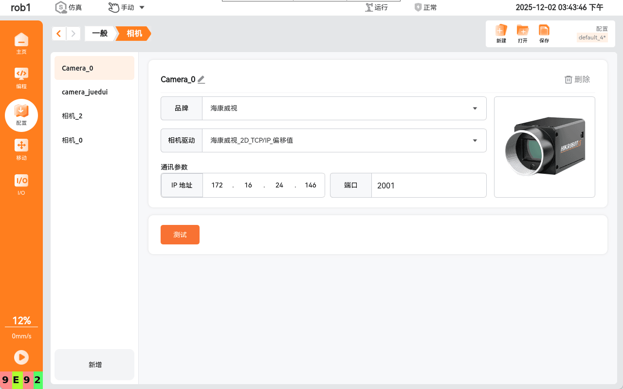
Camera brand
The drop-down list shows the currently supported camera brands.
Driver selection
Select the driver already supported by the current camera brand; drivers are divided into 2D and 3D drivers.
Network configuration
Set the IP address and port number for camera (server) communication.
III. Vision Node Configuration
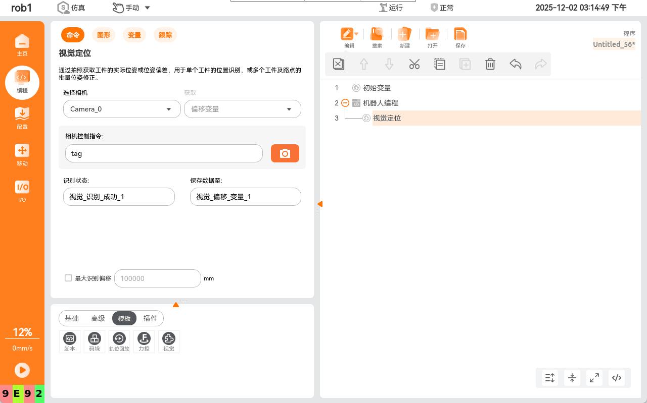
Camera type
The drop-down list shows all validly configured cameras, divided into offset-driver cameras and absolute-driver cameras.
Variable type
Offset-driver cameras can only obtain offset variables; absolute-driver cameras can obtain offset variables and waypoint variables.
Trigger configuration
Control the camera by specifying a string, which can trigger a single photo-capture process.
Variable storage
Variables for storing socket communication data.
IV. Visual Recognition Operation Flow (Using a Hikvision 2D Camera and a Mech-Mind 3D Camera as Examples)
Hikvision Vision Configuration
Use Hikvision's designated software (VisionMaster, hereinafter "vm") to connect the camera.
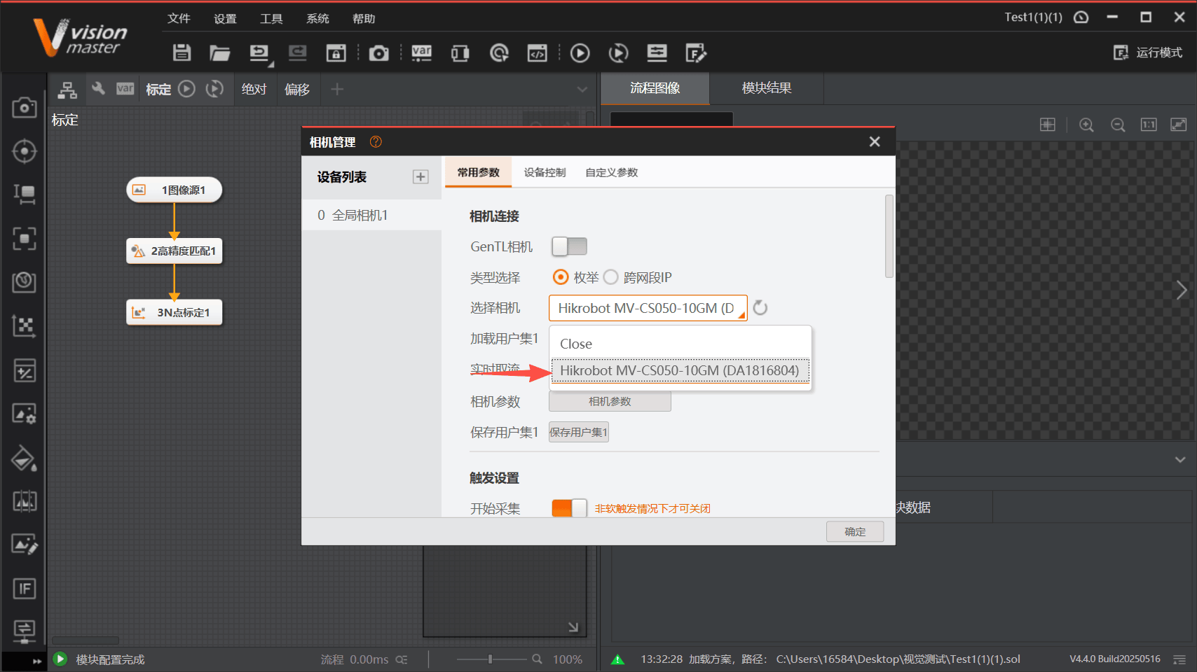
In communication management, add the server network information to complete socket communication and receive and send strings.
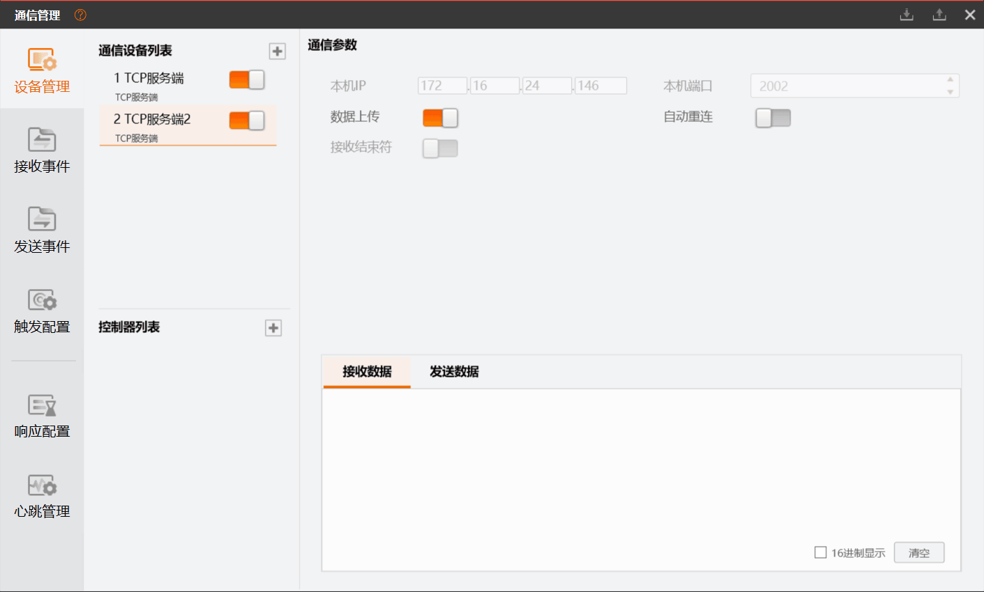
In vm, write the object calibration process, complete the calibration operation, and generate the calibration file.
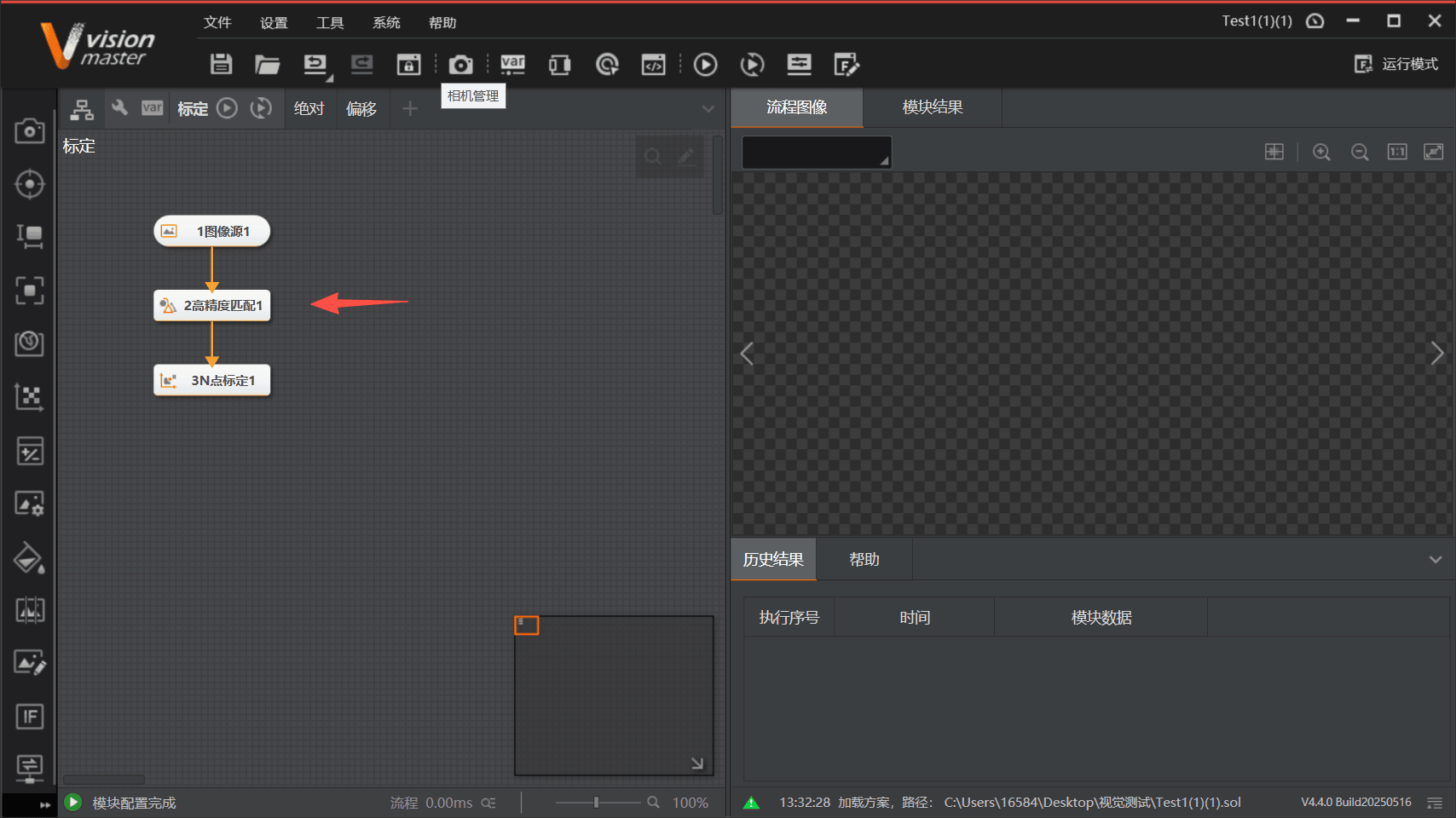
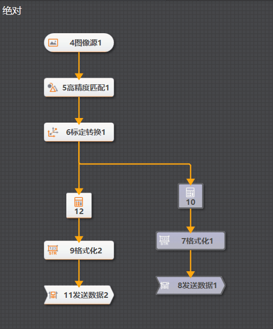
In vm, write the image acquisition and data processing process, and write the corresponding recognition process for the preprocessing stage and for the different types of returned data (such as absolute position and relative position).
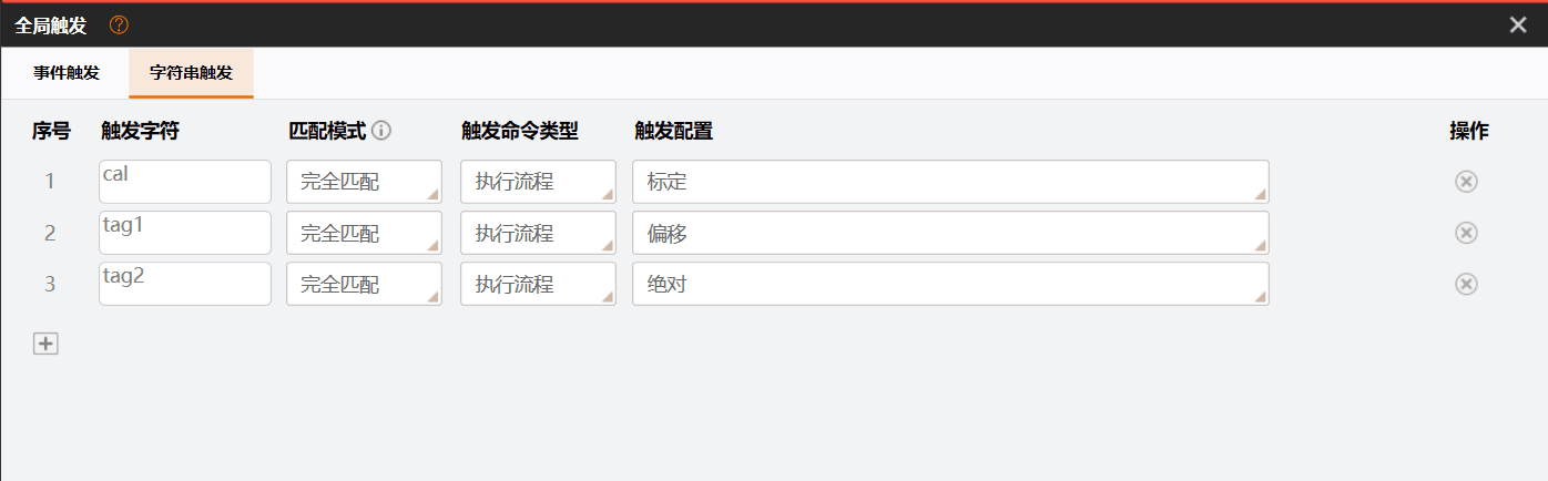
Define the string that triggers the vm recognition process, used for image acquisition and data analysis.
Mech-Mind Vision Configuration
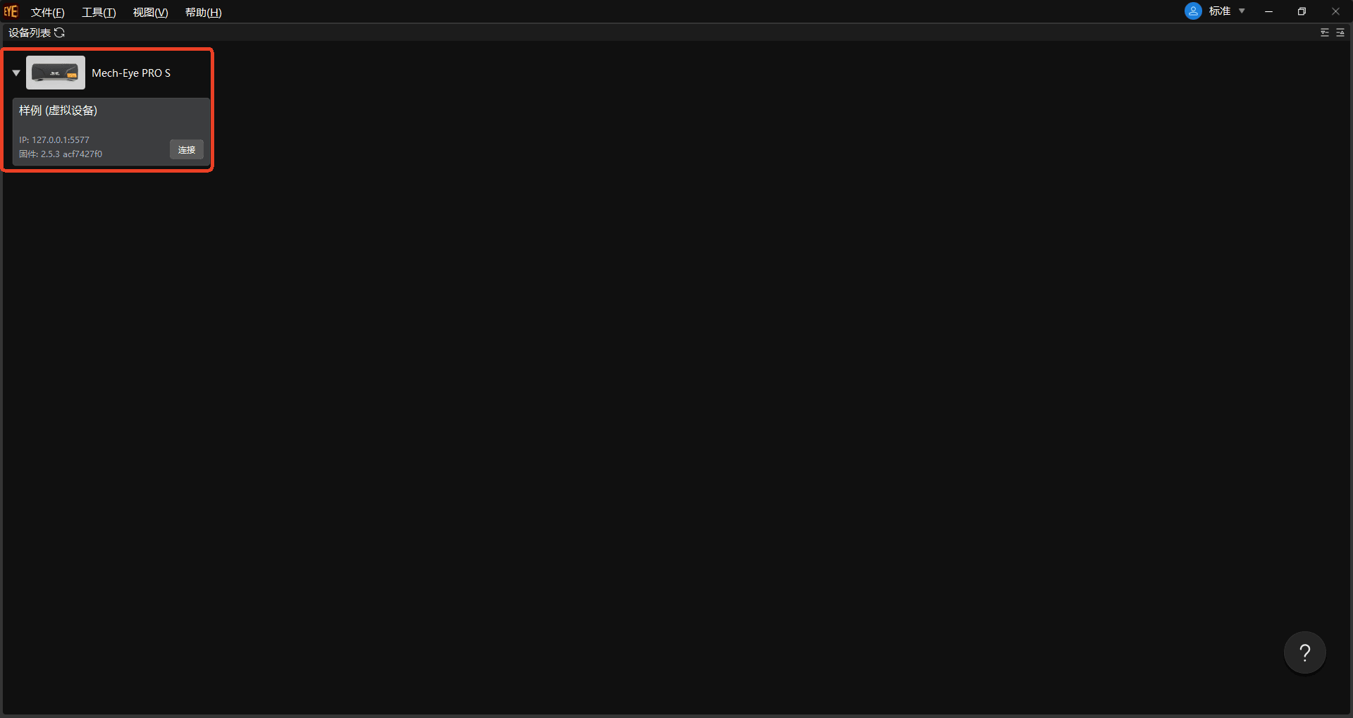
Use Mech-Eye Viewer to connect the camera.
Use Mech-Vision to write the workpiece recognition process.
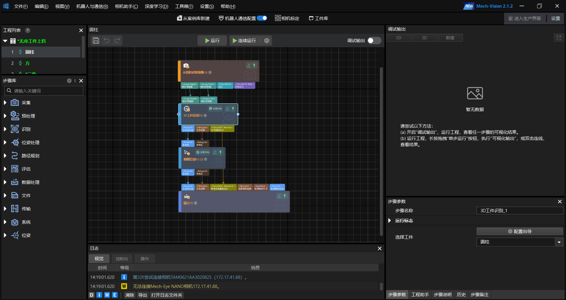
Use Mech-Vision to set the robot arm type and host port number.
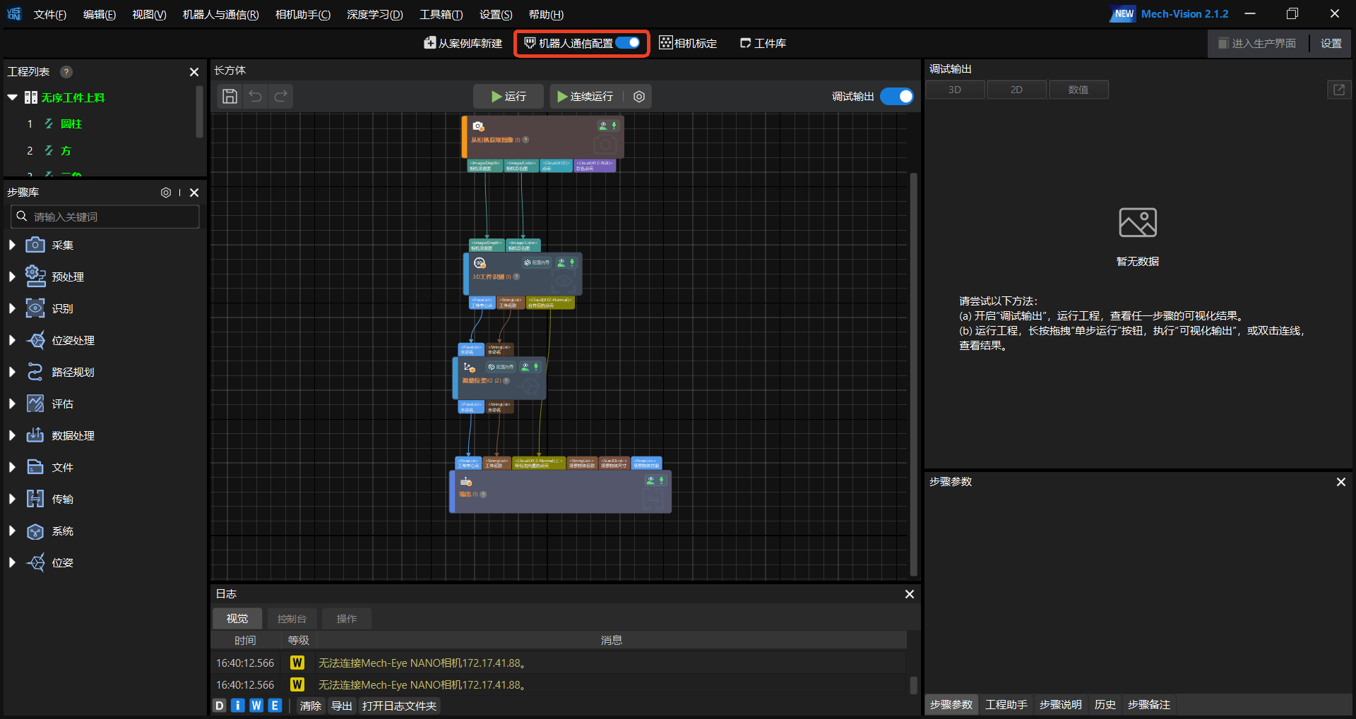
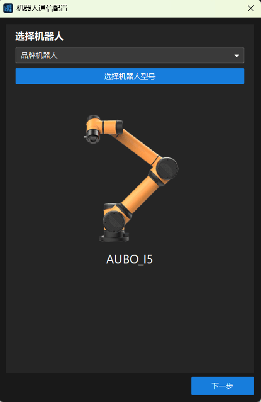
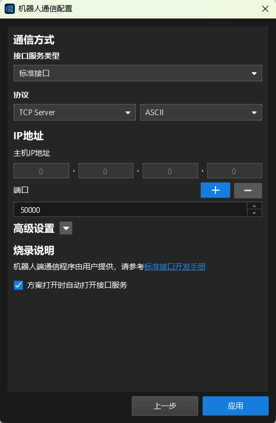
Use Mech-Viz to define the branch number that triggers the Mech-Vision recognition process. The "branch step number, branch number" defined in this step is the ARCS recognition string, used for image acquisition and data analysis.
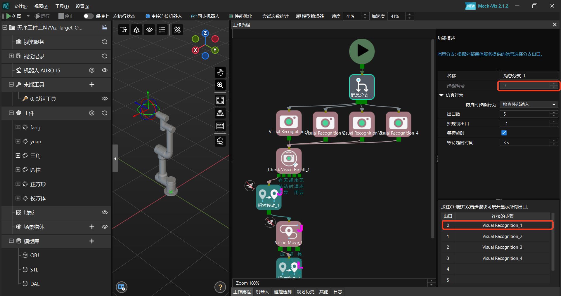
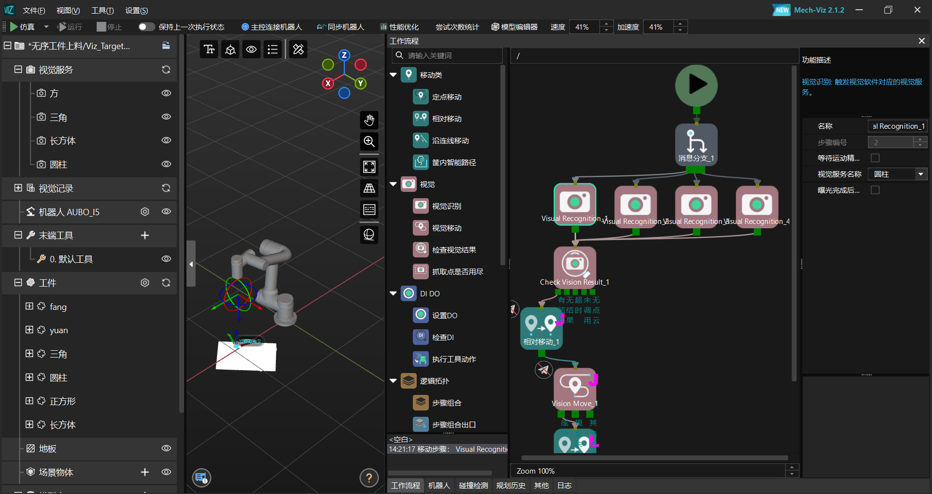
Use Mech-Viz to write the image acquisition and data processing process, and write the corresponding recognition process for the preprocessing stage and for the different types of returned data (such as absolute position and relative position).
ARCS Configuration
In the software, open the "Configuration > General > Camera" page, fill in the server device information and network information, and then click the Test button to test network connectivity.
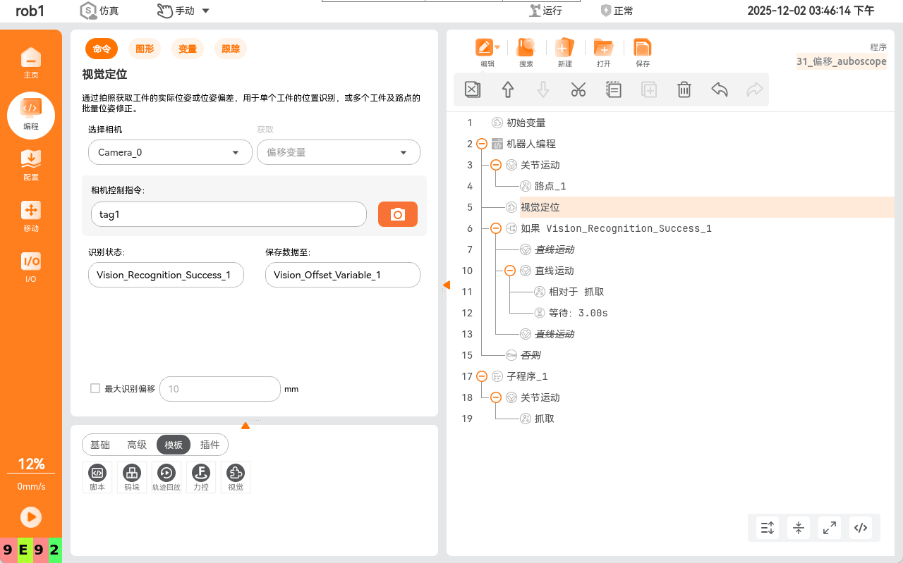
In the programming section, add a vision node and complete the camera selection, trigger configuration, and definition of the data storage variable.
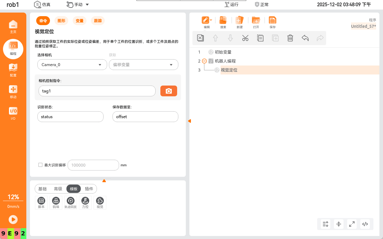
Reasonably apply the data storage variables and write the program tree to complete the final visual grasping (or other action) script logic, for example as shown below.
V. Notes
This guide provides general guidance. During actual implementation, adjustments should be made based on the actual hardware model and production environment requirements. Adequate testing and verification are recommended before formal use.