Coordinate System Calibration Guide
The Coordinate System interface provides three methods for creating a new coordinate system: Point, Line, and Plane. The new coordinate system is established from the taught TCP positions. The following example demonstrates the process of creating a new coordinate system using the Plane method.
Procedure:
Click
Configuration > General > Coordinate Systemto enter theCoordinate Systeminterface.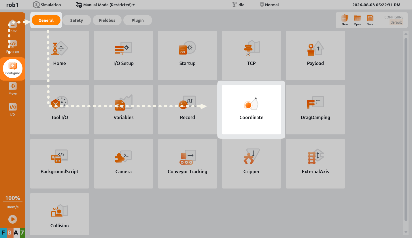
Click
Planeto create a new coordinate system, then selectPlane_0. Three points must be taught to establish the new coordinate system.Point_0: first taught point (origin)Point_1: second taught point (a point on the X-axis)Point_2: third taught point (a point on the XY plane)
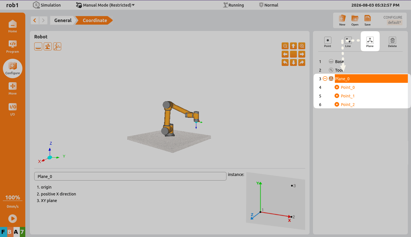
Click
Point_0, then clickEditto enter the teaching interface.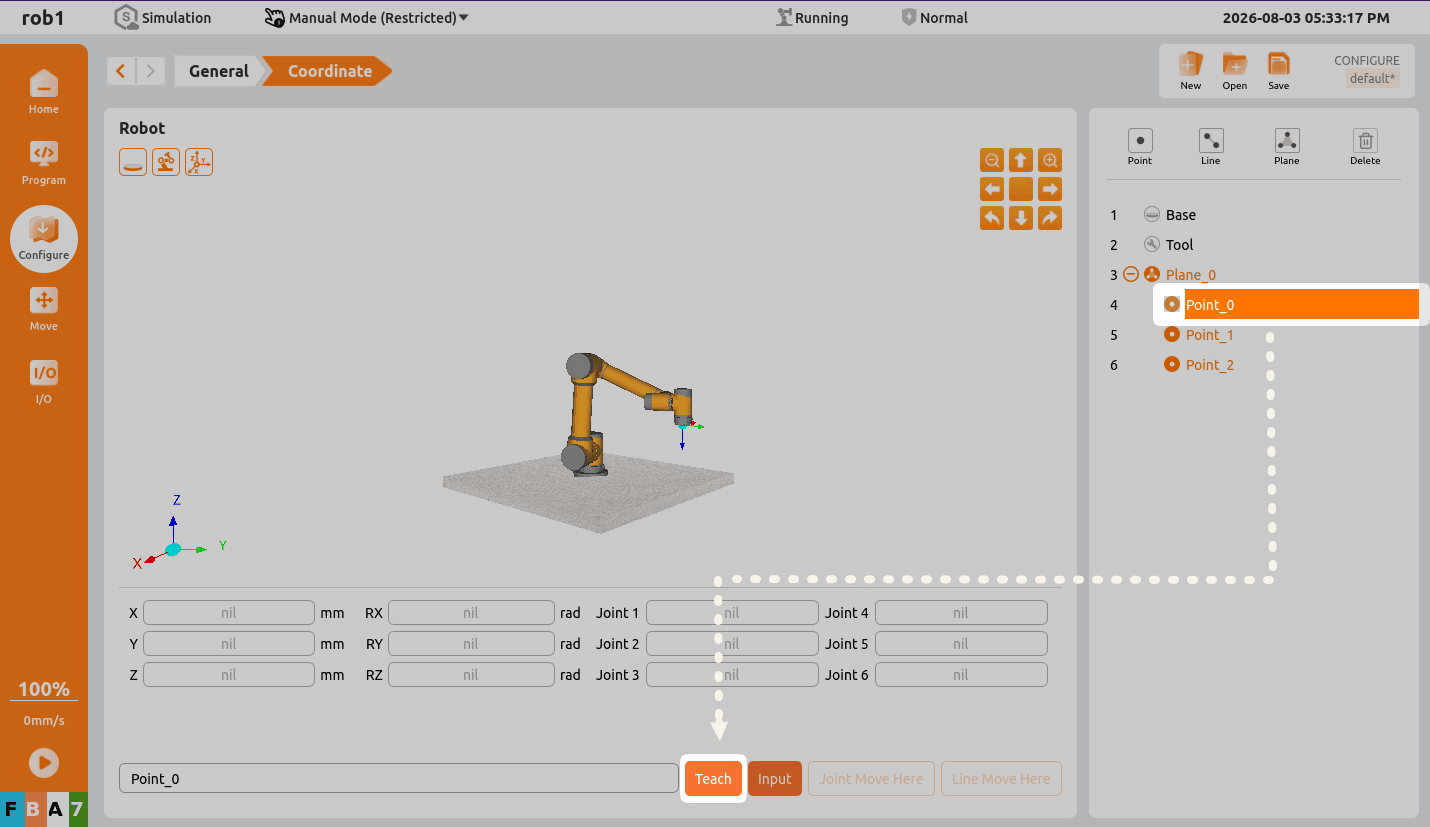
Locate the origin of the plane you want to teach. Move the robot arm to that position, then click
Confirm.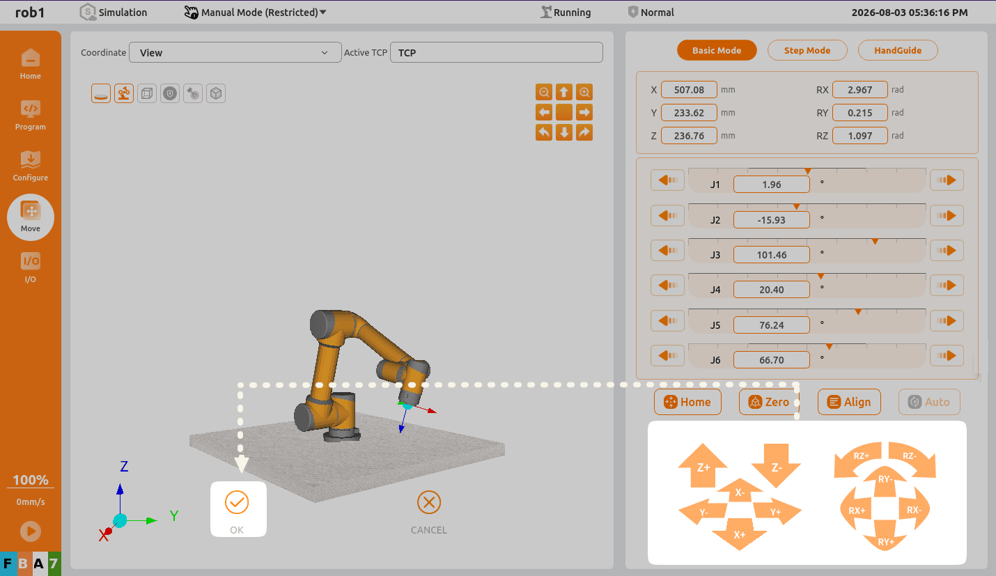
Click
Point_1, then clickEditto enter the teaching interface.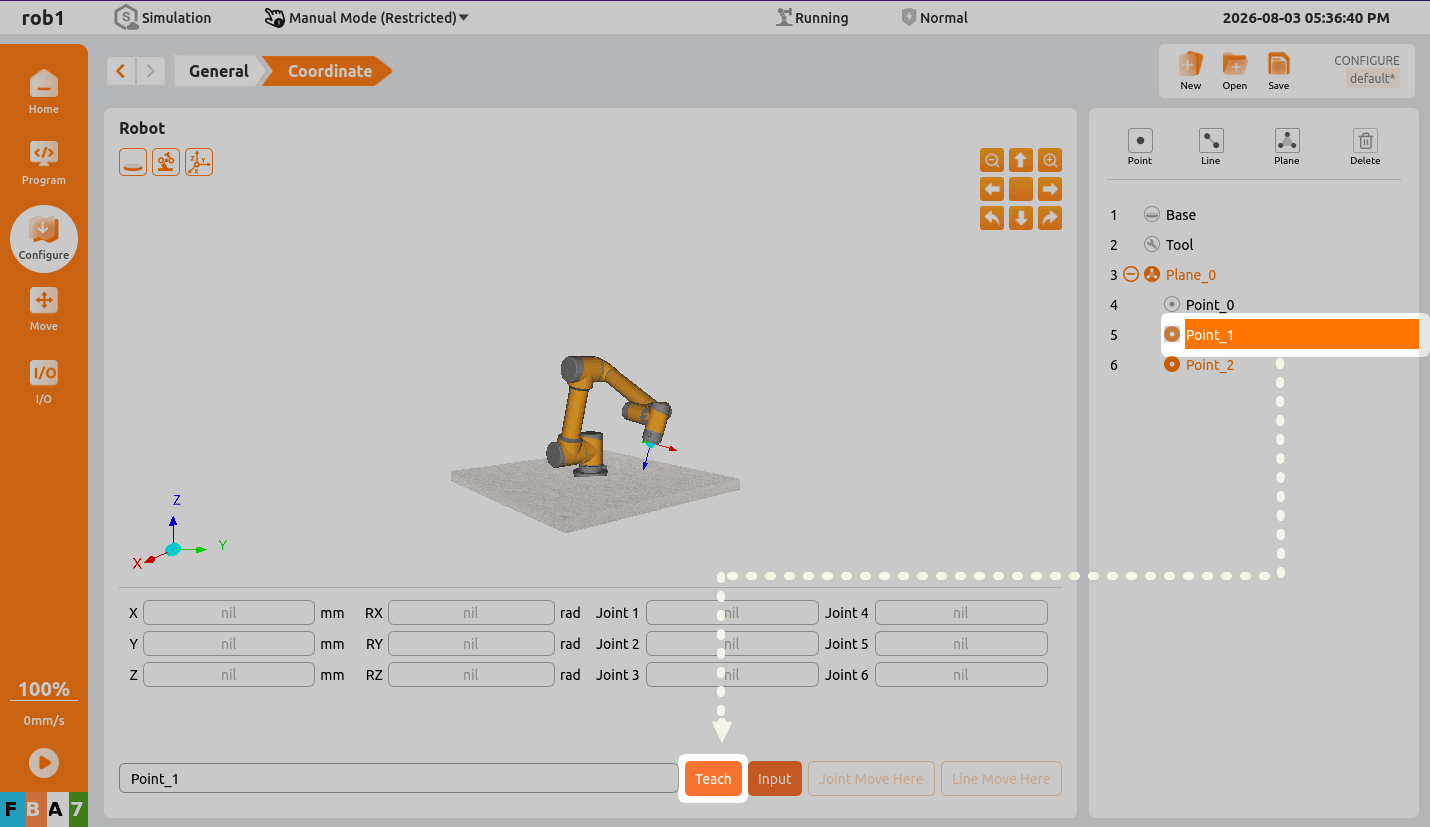
Move the robot arm to the desired point on the X-axis of the plane you want to teach, then click
Confirm.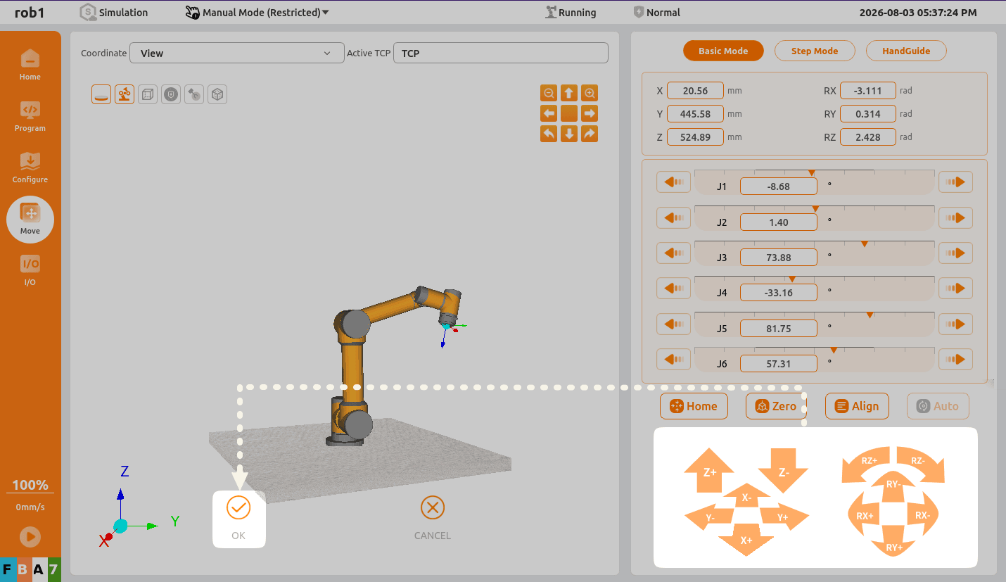
Click
Point_2, then clickEditto enter the teaching interface.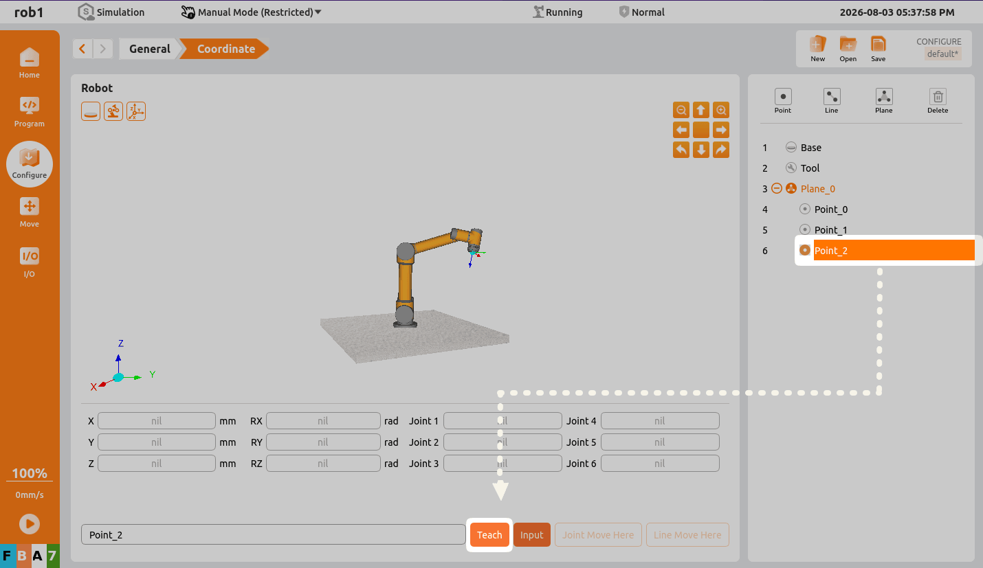
Move the robot arm to the desired point on the XY plane you want to teach, then click
Confirm.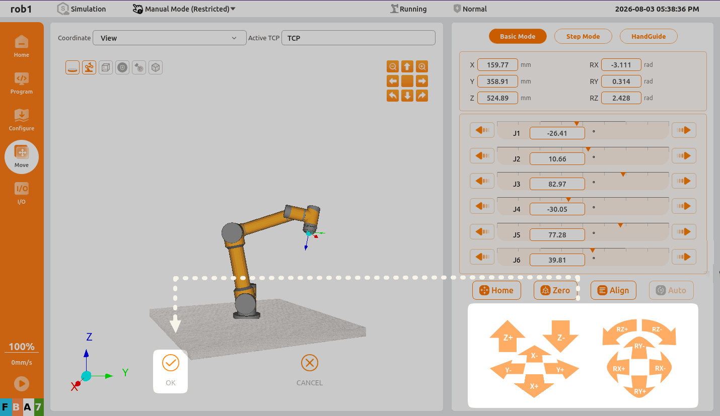
Click
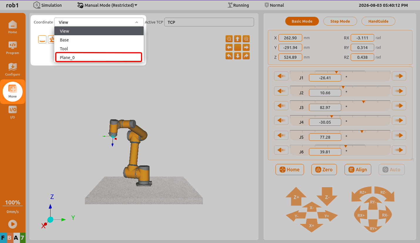
Plane_0. The calibrated coordinate system is displayed in the simulation interface.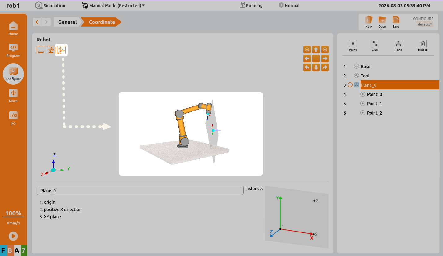
Switch to the teaching interface. In the coordinate system list, the newly created coordinate system
Plane_0is now available.