
AUBO-CB-iS Control Cabinet Cooling System Guide
1 Cooling System Features and Overview
The air in a machining workshop is rich in oil mist, and various dust particles are generated during processing, so the air quality is quite poor. The control cabinet's heat dissipation module uses traditional fan cooling; the air inlet filter is easily covered with dust and clogged by oil residue, losing its filtering ability while also blocking the air inlet and rendering the fan cooling ineffective. The cooling system completely seals the air inlet, uses an oil-water separator to cool and filter the gas, uses a flow meter to monitor the real-time flow rate, and introduces a vortex tube to cool the gas and enhance heat exchange. The airflow is used to push the hot air inside the cabinet out through the fan port, creating continuous positive-pressure ventilation to achieve effective heat dissipation inside the enclosure.
2 Cooling System Structure
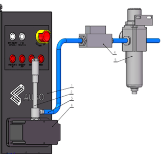
The cooling system mainly consists of an oil-water separator, a flow meter, a vortex tube, a D10 air tube, and an air inlet box. Its composition is shown in the figure below, and the models of each component are listed in Table 2-1.
| No. | Name | Model | Applicable pressure (MPa) | Quantity |
| 1 | Robot control cabinet | AUBO-CB-iS | - | 1 |
| 2 | Vortex tube | Type 08 (change the air inlet connector according to customer requirements) | 0.6-1.2 | 1 |
| 3 | Air tube | D10 | - | 1 |
| 4 | Flow meter | TC5200D-01-L500-G2-EF-P3 | 0-1.0 | 1 |
| 5 | Oil-water separator | Bomin (PDO600S) | 0-1.6 | 1 |
| 6 | Air inlet box AB | Custom machined | - | 1 |
3 Installation Instructions
| Step | Installation diagram | Installation instructions |
| 1 | 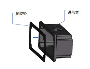 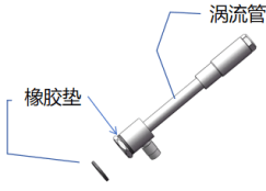 | 1. Use sealant to bond the rubber pad to the bottom of the air inlet box; 2. Use sealant to bond the rubber pad to the position shown in the figure. |
| 2 | 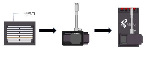 | 1. Remove the filter cotton and protective mesh from the enclosure air inlet; 2. Insert the vortex tube into the upper opening of the air inlet box and lock it in place; 3. Install the air inlet box onto the control cabinet air inlet using M2.5 screws. |
| 3 | 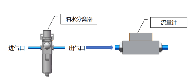 | 1. Connect the oil-water separator air inlet to the air source, and install its air outlet to the flow meter; 2. When installing the oil-water separator and the flow meter, be sure to pay attention to the air inlet and air outlet markings and do not install them in reverse; 3. The oil-water separator must be installed vertically. |
| 4 | 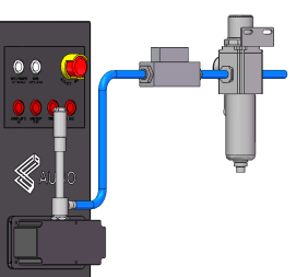 | Use D10 air tubes to connect the installed components together; the fully assembled diagram is shown in the figure. |
4 Temperature Rise Test
Air-Cooled Control Cabinet Temperature Rise Test
Test conditions: An air supply device was connected to the lower air inlet of the AUBO-CB-iS control cabinet, with a compressed gas flow rate of 150 L/min, carrying a 20 kg robot arm for an aging test, with the fan powered and running normally. The results are shown in Table 4-1.
| No. | Set temperature/℃ | CPU heat sink temperature/℃ | Hard disk surface temperature/℃ | Aging result | Test time | |
| 1 | 40 | 44.6 | 47.2 | Functions normal | 10.17 | 18:00-8:30 |
| 2 | 45 | 46.7 | 50.3 | Functions normal | 10.18 | 8:30-13:30 |
| 3 | 50 | 47.9 | 52.8 | Functions normal | 10.18 | 13:30-18:00 |
| 4 | 55 | 48.5 | 54.2 | Functions normal | 10.20 | 8:30-13:30 |
| 5 | 60 | 51.1 | 57.4 | Functions normal | 10.20 | 13:30-18:00 |
| 6 | 65 | 53.5 | 60 | Functions normal | 10.20 | 18:00-8:30 |
5 Usage Precautions and Maintenance
- When connecting to the air source, turn off the air source in advance. After the equipment is fully assembled, close the vortex tube valve. During trial operation, slowly open the vortex tube valve and observe the flow meter's flow change; stop when the desired flow rate is reached.
- Loosen the lock nut on the muffler end of the vortex tube to adjust the air outlet temperature. Note that the adjustment nut must not be screwed all the way in, otherwise the adjustment function will be lost. The upper end of the vortex tube will become hot, so be careful of burns.
- All air tube connectors must be wrapped with thread seal tape counterclockwise around the threads before being tightened.
- Applicable pressure: 0.6-1.2 MPa. If the pressure is too high, the air tube connectors cannot withstand it; if it is below 0.6 MPa, the cooling effect of the vortex tube is limited.
- The oil-water separator does not require filter element replacement. Drying principle: when the compressed air is accelerated through the Venturi separator, water and oil are separated and drop out in the vacuum region.
- The compressed gas must be clean and free of impurities.
- Check weekly for air leaks.
- The service life of the oil-water separator and vortex tube is 3-5 years; replace them promptly once this limit is exceeded.
- Use within the recommended flow rate range; the flow rate should not be too high, and on-site testing only needs to meet the requirements.