
Force Control User Manual
1. Introduction to Main Parameters
Main impedance control parameters of force control:
- M (Mass): affects the impact motion of the robot on the environment. A larger M leads to larger trajectory error and slower system response.
- D (Damping): equivalent to friction. Increasing D reduces the response force overshoot, which slows down the response and increases energy consumption.
- K (Stiffness): the stiffness parameter determines the rigidity of the robot when it is subject to force, acting like a spring; the larger the value, the larger the elastic force.
Parameter examples:
M = {30.0, 30.0, 30.0, 10.0, 10.0, 10.0}
D = {1000, 1000.0, 1000.0, 100.0, 100.0, 100.0}
K = {1000, 1000.0, 0, 100.0, 100.0, 100.0}
2. Script Examples
| Example | Parameters | Description |
|---|---|---|
| Example 1 | K=0 goal_force=0 | Demonstrates the drag effect; after dragging, the robot holds its position and does not return to the original position. |
| Example 2 | K>0 goal_force=0 | Demonstrates the spring effect; after dragging and releasing, the robot returns to the original position. |
| Example 3 | K=0 D=100 goal_force=-5 | Under the conditions of Example 1, only a target force is added separately. The robot is affected by the target force and keeps moving in the direction that satisfies the target force balance, stopping only after the applied external force reaches equilibrium with the target force. |
| Example 4 | K=500 D=100 goal_force=-5 | Under the conditions of Example 2, only a target force is added separately. The robot moves a certain distance under the influence of the target force, but the spring state exerts a rebounding force on the robot. When the spring force reaches equilibrium with the target force, the robot becomes stationary and then remains in the spring state. |
| Example 5 | Move(Y400 > Y500) K=100 D=100 goal_force=0 | Under the conditions of Example 2, the motion direction is modified. The robot remains in the spring state throughout. While moving in the Move direction, after an external force is applied in the Z direction, the robot returns to its original Z position under the spring force; after Move ends, it is still in the spring state. |
| Example 6 | Move(Y400 > Y500) K=100 D=100 goal_force=-1 | Under the conditions of Example 5, the robot remains in the spring state throughout. While moving in the Move direction, affected by the target force, the robot moves a certain distance in the Z direction toward the direction that balances the target force; when the spring force reaches equilibrium with the target force, the Z-direction motion stops and the robot is in the spring state. After Move ends, the robot's Z is below the target position. |
| Example 7 | First stage: the Z-direction motion reaches a steady state; a reference trajectory is set whose endpoint is about 1 mm above the table contact surface, and the force-guiding effect of Example 6 is used to reach the equilibrium state. Second stage: using the equilibrium point of the first stage as the reference point, a straight line is drawn by moving 100 mm along the Y direction. Force control keeps the force at 1 N throughout the straight-line drawing under force guiding. | |
| Example 8 | First stage: the Z-direction motion reaches a steady state; a reference trajectory is set whose endpoint is about 1 mm above the table contact surface, and the force-guiding effect of Example 6 is used to reach the equilibrium state. Second stage: using the equilibrium point of the first stage as the reference point, a circle is drawn by setting two other points at the same height. During drawing, force guiding adjusts based on actual force feedback to complete the circle drawing. |
- When K is 0 and no target force is set, the robot is in a drag effect.
- When K is greater than 0 and no target force is set, a spring effect occurs; the larger K is, the stiffer the spring.
- When K is 0 and both D and a target force are set, a force-guiding situation occurs: without any external force, the robot keeps moving, with its speed proportional to the force and inversely proportional to the damping, until it encounters an opposite-direction force that reaches equilibrium with the target force.
- When K is not 0 and both D and a target force are set, the robot drops a certain distance, then stops and maintains the spring state. The force required to resist the drop equals the set target force.
- If Move exists, the above four actions continue after Move completes.
Note
The force control direction for all scripts is Z; the set K and D values are all in the Z direction.
Initial pose: pose_z = 400, pose_y = 400.
Move speed: v = 10.
Example 1: Drag
Description: when K is 0 and no target force is set, the robot is in a drag effect: applying an external force to the end makes the robot move in the direction of the force without returning to the original position.
Parameter settings:
M = {30.0, 30.0, 30.0, 10.0, 10.0, 10.0}
D = {1000.0, 1000.0, 100.0, 100.0, 100.0, 100.0}
K = {1000, 1000.0, 0, 100.0, 100.0, 100.0}
goal_force = 0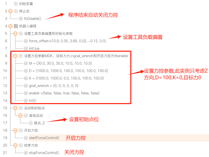
Situation description: demonstrates the force control drag effect; after dragging, the robot holds its position and does not return. The smaller D is, the lighter the dragging feels.
Robot arm drag video example:
Example 1 related files:
Example 2: Spring
Description: when K is not 0 and no target force is set, a spring effect occurs; the larger K is, the stiffer the spring, meaning the farther from the current position, the greater the required force. After the external force is removed, the robot returns to the original position.
Parameter settings:
M = {30.0, 30.0, 30.0, 10.0, 10.0, 10.0}
D = {1000.0, 1000.0, 100.0, 100.0, 100.0, 100.0}
K = {1000, 1000.0, 100, 100.0, 100.0, 100.0}
goal_force = 0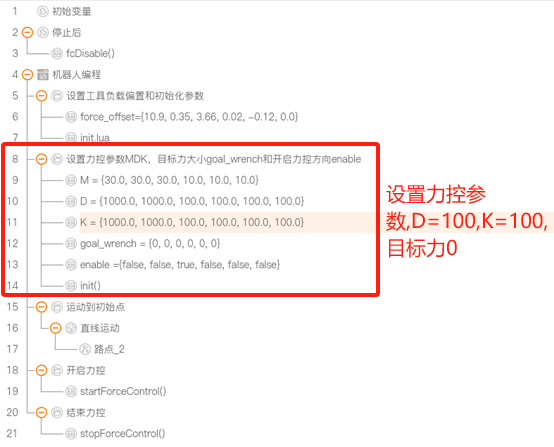
Situation description: Demonstrates the force control spring effect; after dragging and releasing, the robot returns to the original position. The larger K is, the stiffer the spring.
Robot arm spring effect video example:
Example 2 related files:
Example 3: Drag with Target Force
Description: A target force of -5N is added to the drag demonstrated in Example 1. The robot is affected by the target force and keeps moving in the direction that can balance the target force until an equal external force makes the robot reach the equilibrium state, at which point the robot stops moving. In this example, the target force is -5N, so the robot moves downward until an upward external force of 5N is applied to the tool to reach the equilibrium state.
Parameter settings:
M = {30.0, 30.0, 30.0, 10.0, 10.0, 10.0}
D = {1000.0, 1000.0, 100.0, 100.0, 100.0, 100.0}
K = {1000, 1000.0, 0, 100.0, 100.0, 100.0}
goal_force = -5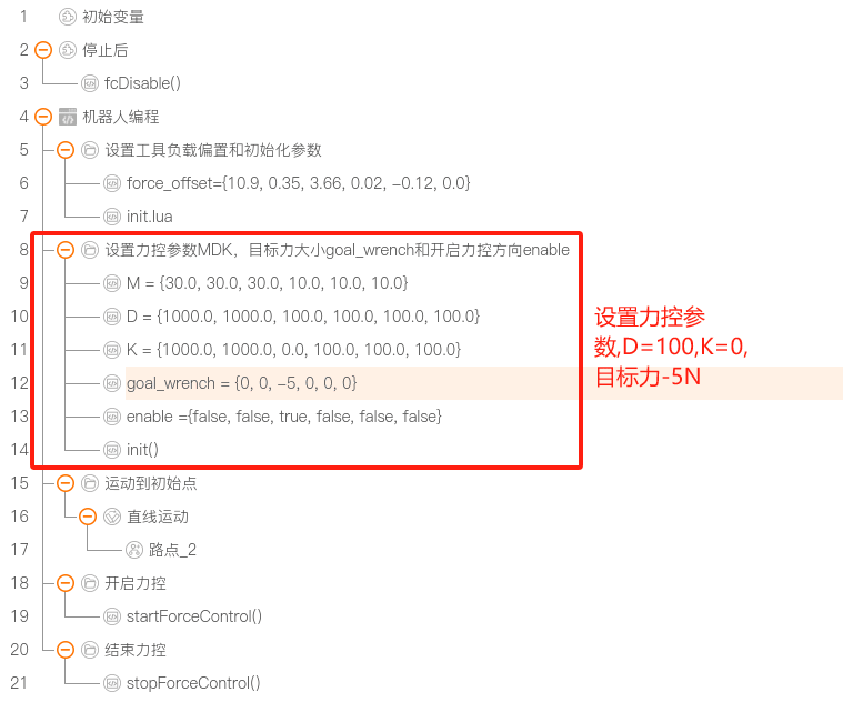
Situation description:
Without applying an external force, the robot keeps moving downward.
Applying a 5N force keeps the robot stationary; if a force greater than 5N is applied, the robot moves upward.
Drag with target force video example:
Example 3 related files:
Example 4: Spring with Target Force
Description: A target force of -5N is added to the spring demonstrated in Example 2. The robot is affected by the target force and moves in the direction that can balance the target force. Unlike Example 3, where an equal external force reaches the steady state, in the spring state the distance moved by the end produces a force in the opposite direction. After it reaches equilibrium with the set target force, the robot is in a new spring state.
Parameter settings:
  M = {30.0, 30.0, 30.0, 10.0, 10.0, 10.0}
  D = {1000.0, 1000.0, 100.0, 100.0, 100.0, 100.0}
  K = {1000, 1000.0, 500, 100.0, 100.0, 100.0}
  goal_force = -5
Situation description:
- Without applying a force, the robot moves to about 390 and stops, then remains in the spring state.
- Applying an external force to hold pose_z at 400 requires about 5N.
Spring with target force video example:
Example 4 related files:
Example 5: Spring with a Y+ Reference Trajectory
Description: a reference trajectory is added to the spring demonstrated in Example 2, moving 100 mm in the Y+ direction. The robot remains in the spring state throughout. While moving in the Y+ direction, after an external force is applied in the Z direction, the robot returns to its original Z position under the spring force; after Move ends, it is still in the spring state.
Parameter settings:
M = {30.0, 30.0, 30.0, 10.0, 10.0, 10.0}
D = {1000.0, 1000.0, 100, 100.0, 100.0, 100.0}
K = {1000, 1000.0, 100, 100.0, 100.0, 100.0}
goal_force = 0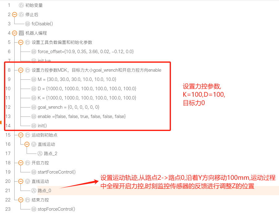
Situation description:
Without applying an external force: the robot moves from y400 to y500, and from z400 to z386, then remains in the spring state.
When a maximum force condition is set, if the force exceeds the maximum limit and satisfies
isCondFullfiled(), the robot stops moving.Chart display:

Example 5 related files:
Example 6: Spring with a Y+ Reference Trajectory and Target Force
Description: a target force is added to the spring demonstrated in Example 5. The robot remains in the spring state throughout. While moving in the Move direction, affected by the target force, the robot moves in the Z direction toward the direction that balances the target force; when the spring force reaches equilibrium with the target force, the Z-direction motion stops. After Move ends, the robot's Z is below the target position.
Parameter settings:
M = {30.0, 30.0, 30.0, 10.0, 10.0, 10.0}
D = {1000.0, 1000.0, 100, 100.0, 100.0, 100.0}
K = {1000, 1000.0, 100, 100.0, 100.0, 100.0}
goal_force = -1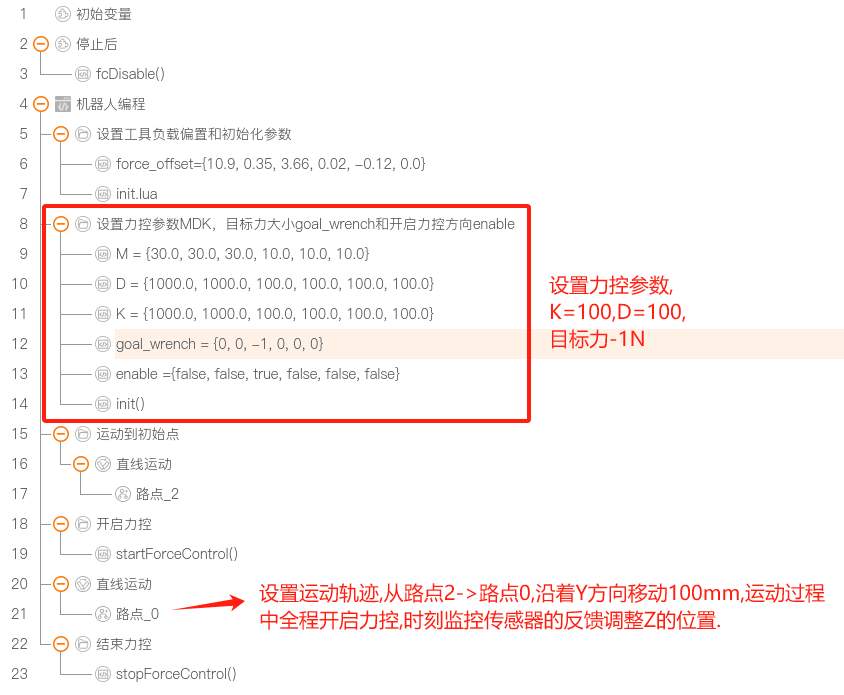
Situation description:
Without applying an external force: the robot moves from y400 to y500, and from z400 to z386, then remains in the spring state.
If z400 is above the table surface, when force control is enabled, the robot moves from y400 to y500 and continuously applies a pressure of about 1N to the table surface.
Chart display:

Example 6 related files:
Example 7: Drawing a Straight Line
Description: to intuitively demonstrate the force control effect, this example draws a straight line in two stages.
- In the first stage, the robot descends vertically in the Z direction to the table surface and reaches the equilibrium state. The whole process goes from "Waypoint 2 > Waypoint 0 > target_pose > force equilibrium point". In the "Waypoint 2 > Waypoint 0" process the robot quickly closes the distance; the "Waypoint 0 > target_pose" path is the reference trajectory. To reduce the impact caused by the robot's speed, target_pose is set to a position 1 mm above the table contact. After reaching target_pose, driven by the target force, the robot continues to descend until it contacts the table and reaches the force equilibrium state; the force equilibrium point does not need to be set separately. The end conditions include motion timeout, motion in place, motion reaching the steady state, and a protective stop when force control exceeds the maximum force.
- In the second stage, using the force equilibrium point as the reference point, a straight line is drawn by moving 100 mm in the Y+ direction from the reference point. The force control state acts over the whole drawing process, keeping the force at about 1N until the straight line is fully drawn. The end conditions include motion timeout, motion in place, and a protective stop when force control exceeds the maximum force.
Parameter configuration:
First stage parameter configuration:
M = {30.0, 30.0, 10.0, 10.0, 10.0, 10.0}
D = {1000.0, 1000.0, 600, 100.0, 100.0, 100.0}
K = {1000, 1000.0, 0, 100.0, 100.0, 100.0}
goal_force = 1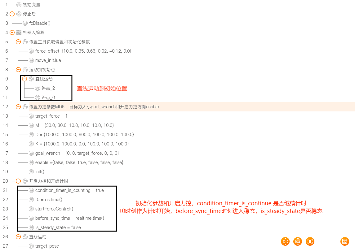
Second stage parameter configuration:
M = {30.0, 30.0, 10.0, 10.0, 10.0, 10.0}
D = {1000.0, 1000.0, 600, 100.0, 100.0, 100.0}
K = {1000, 1000.0, 0, 100.0, 100.0, 100.0}
goal_force = 1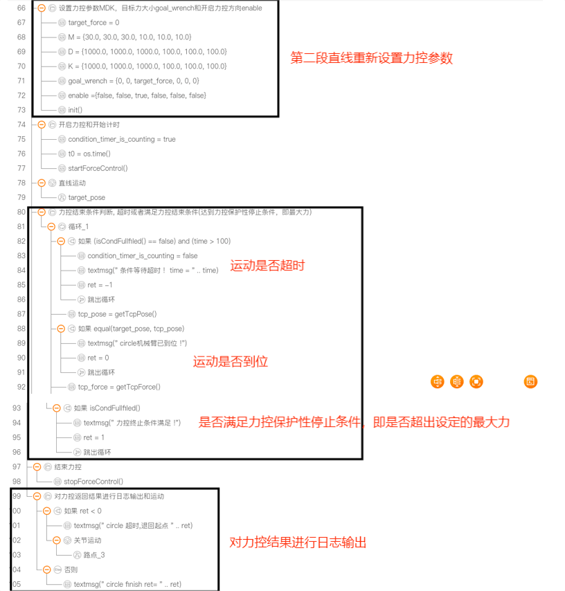
Robot arm straight-line drawing video example:
Example 7 related files:
Example 8: Drawing a Circle
Description: to intuitively demonstrate the force control effect, this example draws a circle in two stages.
- In the first stage, the robot descends vertically in the Z direction to the table surface and reaches the equilibrium state. The whole process goes from "Waypoint 2 > Waypoint 0 > target_pose > force equilibrium point". In the "Waypoint 2 > Waypoint 0" process the robot quickly closes the distance; the "Waypoint 0 > target_pose" path is the reference trajectory. To reduce the impact caused by the robot's speed, target_pose is set to a position 1 mm above the table contact. After reaching target_pose, driven by the target force, the robot continues to descend until it contacts the table and reaches the force equilibrium state; the force equilibrium point does not need to be set separately. The end conditions include motion timeout, motion in place, motion reaching the steady state, and a protective stop when force control exceeds the maximum force.
- In the second stage, using the force equilibrium point as the reference point and keeping Z unchanged at the reference point, two other reference points are set, and these three points form a circular trajectory. The configured circular reference trajectory is fed to force control, which corrects the circular trajectory based on the force feedback values, keeping the force at about 1N until the circle is fully drawn. The end conditions include motion timeout, motion in place, and a protective stop when force control exceeds the maximum force.
Parameter configuration:
First stage parameter configuration:
M = {30.0, 30.0, 10.0, 10.0, 10.0, 10.0}
D = {1000.0, 1000.0, 600, 100.0, 100.0, 100.0}
K = {1000, 1000.0, 0, 100.0, 100.0, 100.0}
goal_force = 1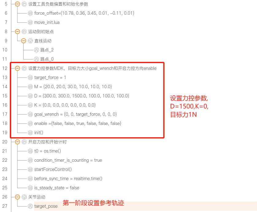
Second stage parameter configuration:
M = {30.0, 30.0, 10.0, 10.0, 10.0, 10.0}
D = {1000.0, 1000.0, 600, 100.0, 100.0, 100.0}
K = {1000, 1000.0, 0, 100.0, 100.0, 100.0}
goal_force = 1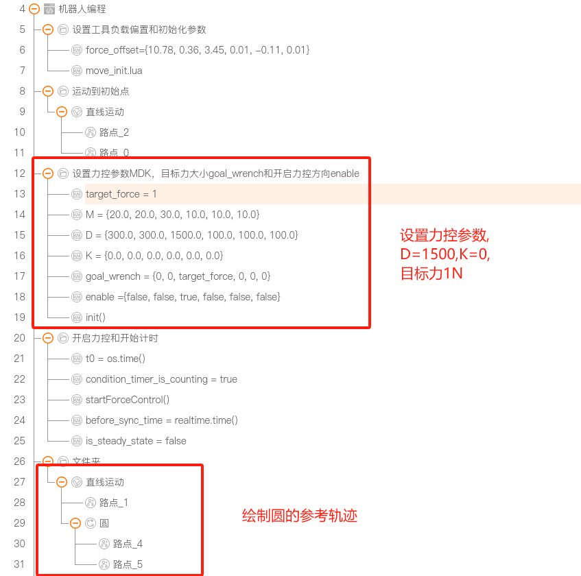
Robot arm circle-drawing video example:
Example 8 related files: