
Robot TCP Calibration Guide
1 Terminology and Basic Concepts
TCP (Tool Center Point): The working point of the robot's end tool. It is the actual contact point between the robot and the workpiece during task execution.
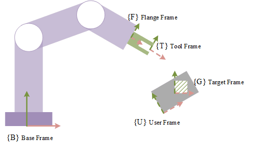
Tool Coordinate System: A coordinate system established with the TCP as its origin, used to describe the position and orientation of the tool relative to the robot flange.
In practical production, different tools are typically mounted on the robot flange. To accurately control the tool's position and orientation during operation, the TCP and the Tool Coordinate System must be calibrated. The purpose of Tool Coordinate System calibration is to obtain an accurate description of the Tool Coordinate System relative to the Flange Coordinate System.
The typical TCP calibration error is within 0.5–1 mm. For applications requiring high TCP accuracy, additional equipment (such as optical tracking systems) is required for precise calibration.
2 TCP Calibration Principles and Methods
2.1 Calibrating the Tool Coordinate System Origin (TCP Position)
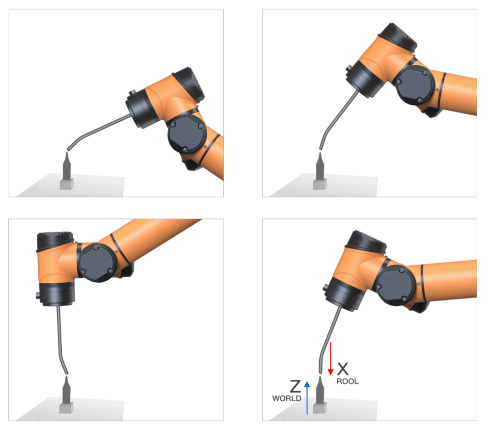
The TCP position is calibrated using the four-point method. A fixed reference point (typically a sharp tip) is selected, and the robot tool tip is taught at the same reference point in four different poses. The system automatically calculates the TCP position based on the data collected from these four poses.
The differences between the four poses should be as large as possible to improve calculation accuracy.
2.2 Calibrating the Tool Coordinate System Orientation (TCP Orientation)
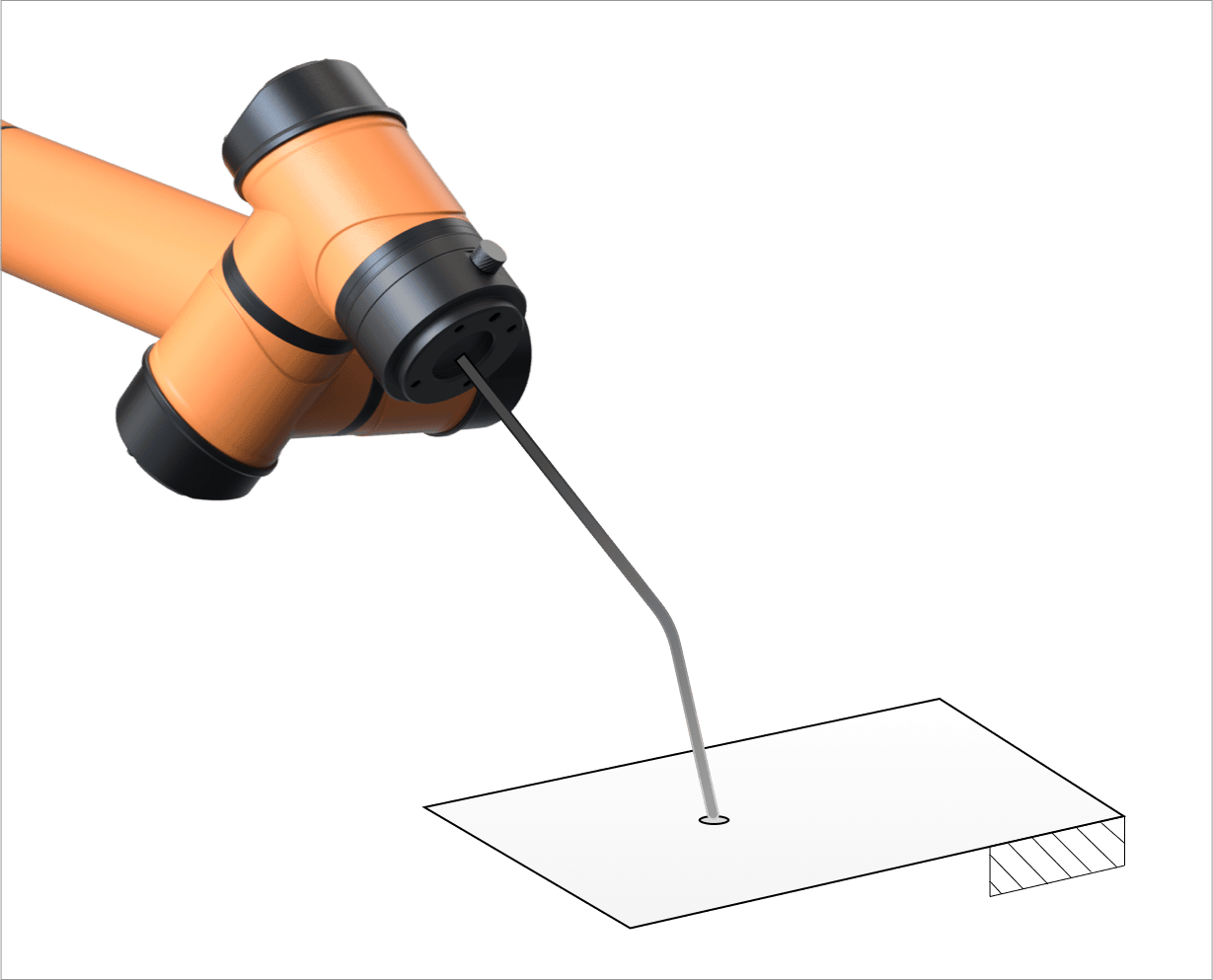
The TCP orientation is calibrated using a reference coordinate system and a point on a plane. Select a reference coordinate system, then select a point in that coordinate system. The orientation of the reference coordinate system will be assigned to that point.
3 TCP Accuracy Verification Methods
After calibration, the TCP accuracy must be verified to ensure that it meets the application requirements. The following are two commonly used verification methods.
3.1 Tip-Centered Rotation Method

Procedure:
- Install a sharp tip on the robot flange.
- Enter the TCP coordinates of the current tip into the teach pendant as the robot TCP.
- Add another sharp tip in the workspace and secure it in place.
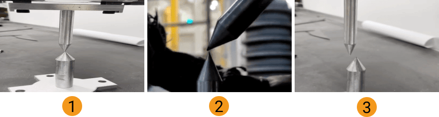
- Use the teach pendant to move the robot until the robot's tip precisely contacts the tip in the workspace (tip-to-tip contact).
- Use the teach pendant to rotate the robot about the current TCP as the center, and observe the overlap of the two tips and the range of distance variation.
Verification Results Comparison:
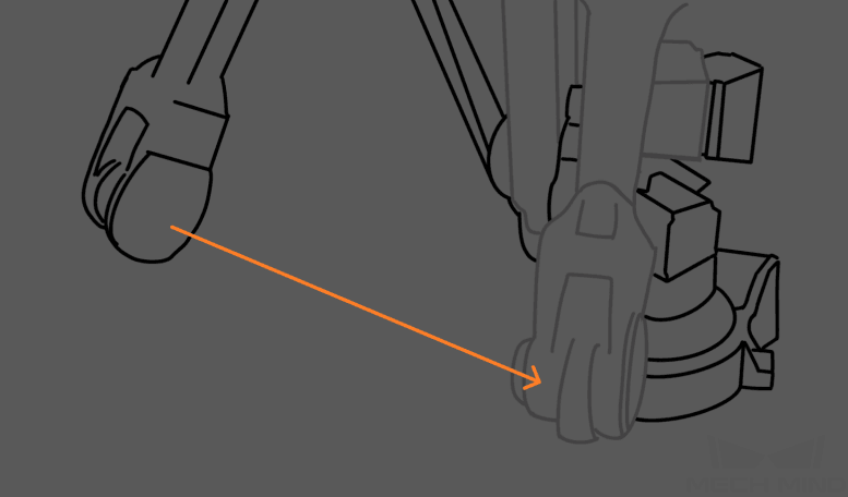
3.2 Measuring Travel Distance Error
Procedure:
- In the workspace, use the teach pendant to move the robot a specified distance along a fixed direction (for example, the X- or Y-axis).
- After the movement is complete, measure the robot's actual travel distance.
- Calculate the error: travel distance error = preset distance − actual travel distance.
For example, use the teach pendant to move the robot 1000 mm along the X-axis, then measure the actual travel distance. If the robot has actually moved 998 mm, the travel distance error is 2 mm.
4 Configuring the Tool Coordinate System in the Teaching Software
4.1 Teaching the TCP Position
Open the ARCS teaching software. Click
Configuration > General > Tool Center Pointto enter theTool Center Pointinterface.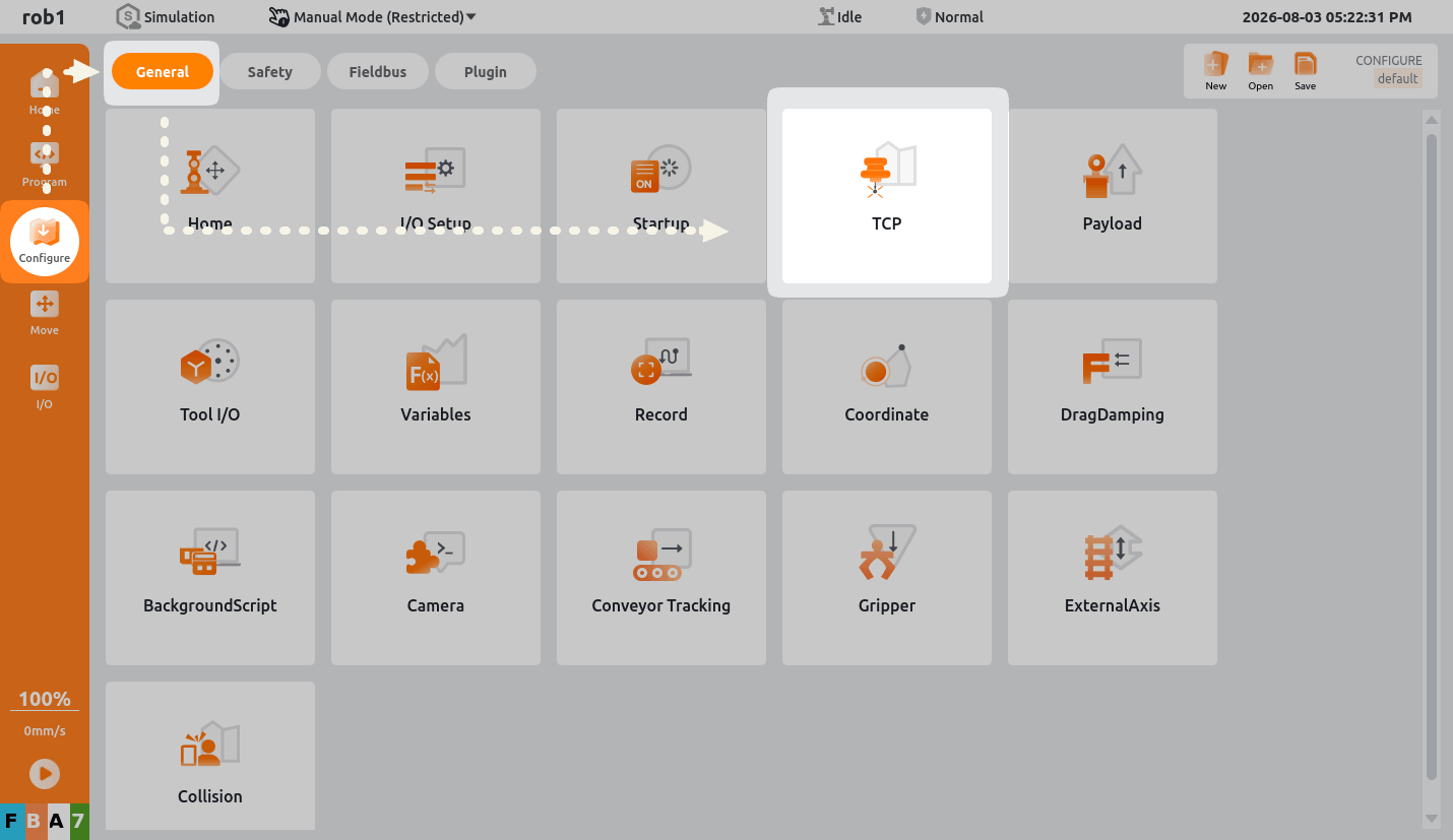
Click
Addto createTCP_1, then clickPosition > Measureto enter theTeach TCP Positionwizard.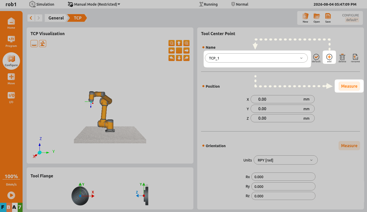
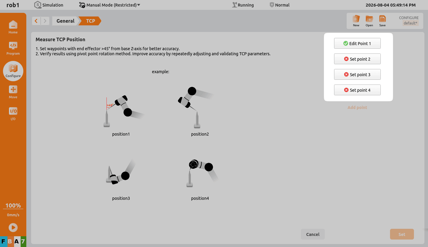
Teach four positions, setting the pose of each position as shown in the example.
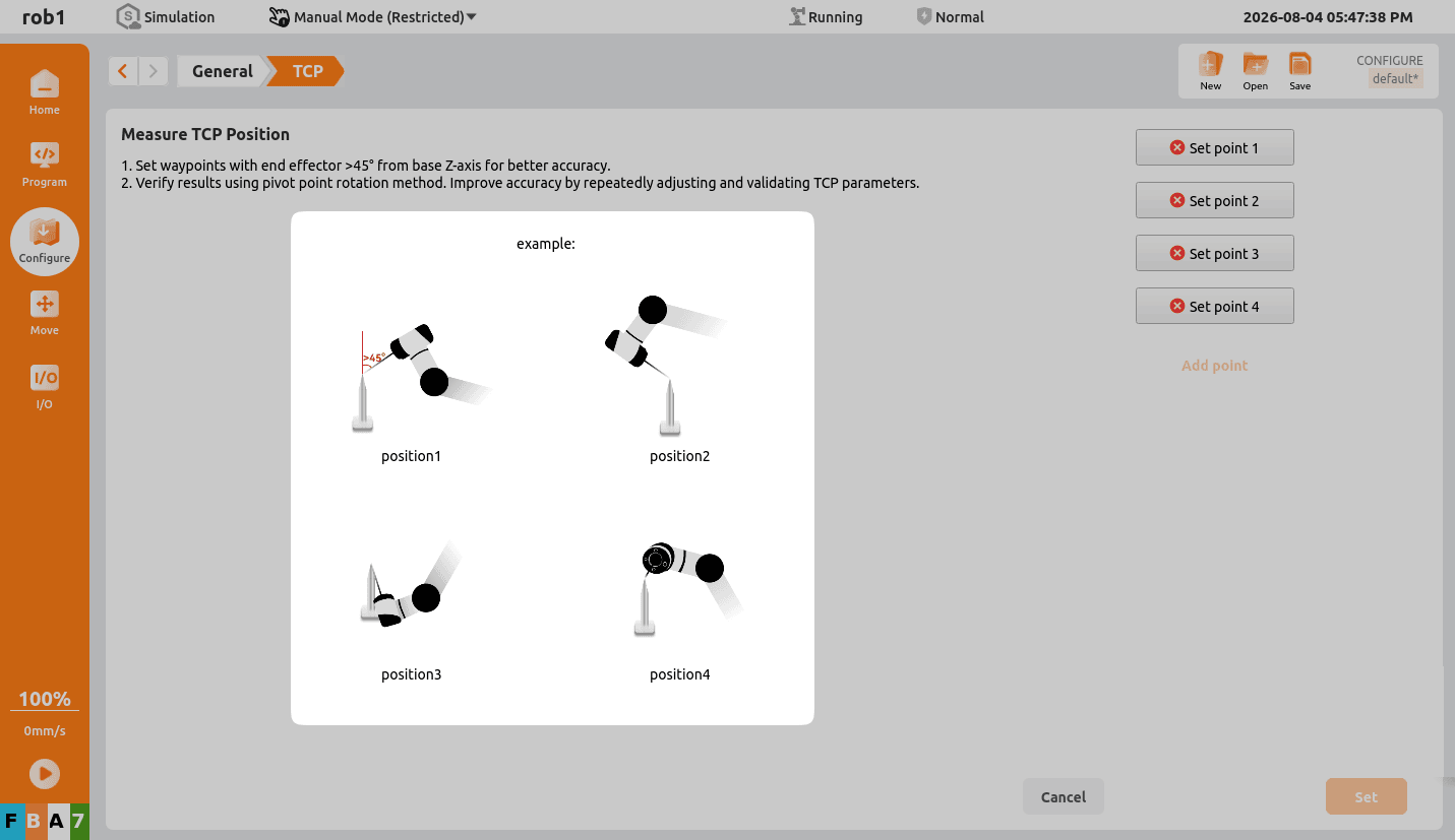
Click
Set Point 1to enter the teaching interface. Teach Point 1, then clickConfirmto save the setting and exit the teaching interface.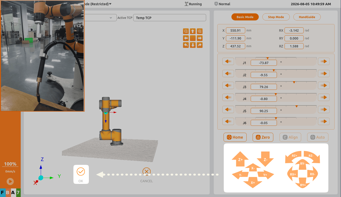
The point status icons are described in the following table.
Status Icon Configured point 
Point to be configured 
Repeat the preceding process to set Point 2.
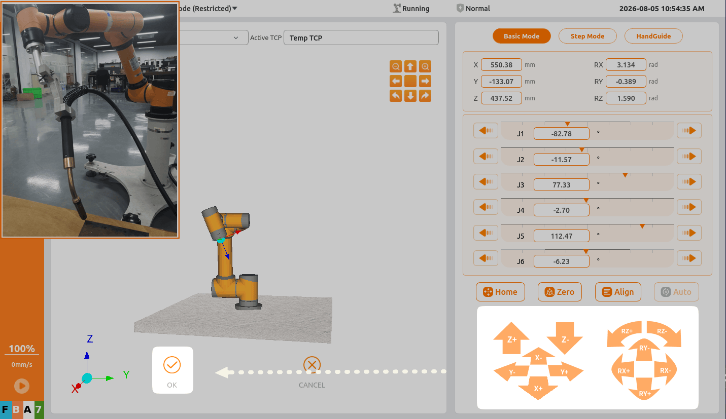
Repeat the preceding process to set Point 3.
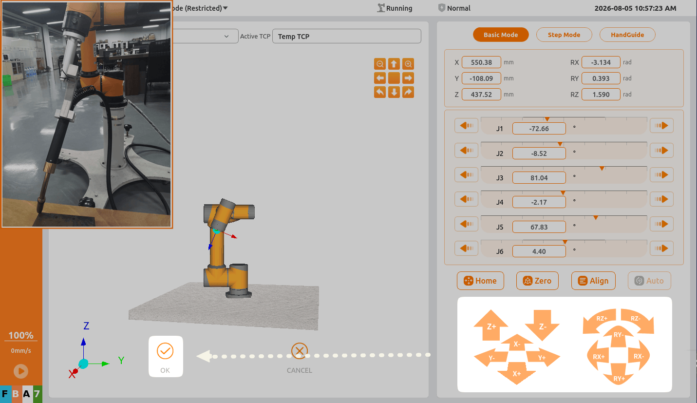
Repeat the preceding process to set Point 4.
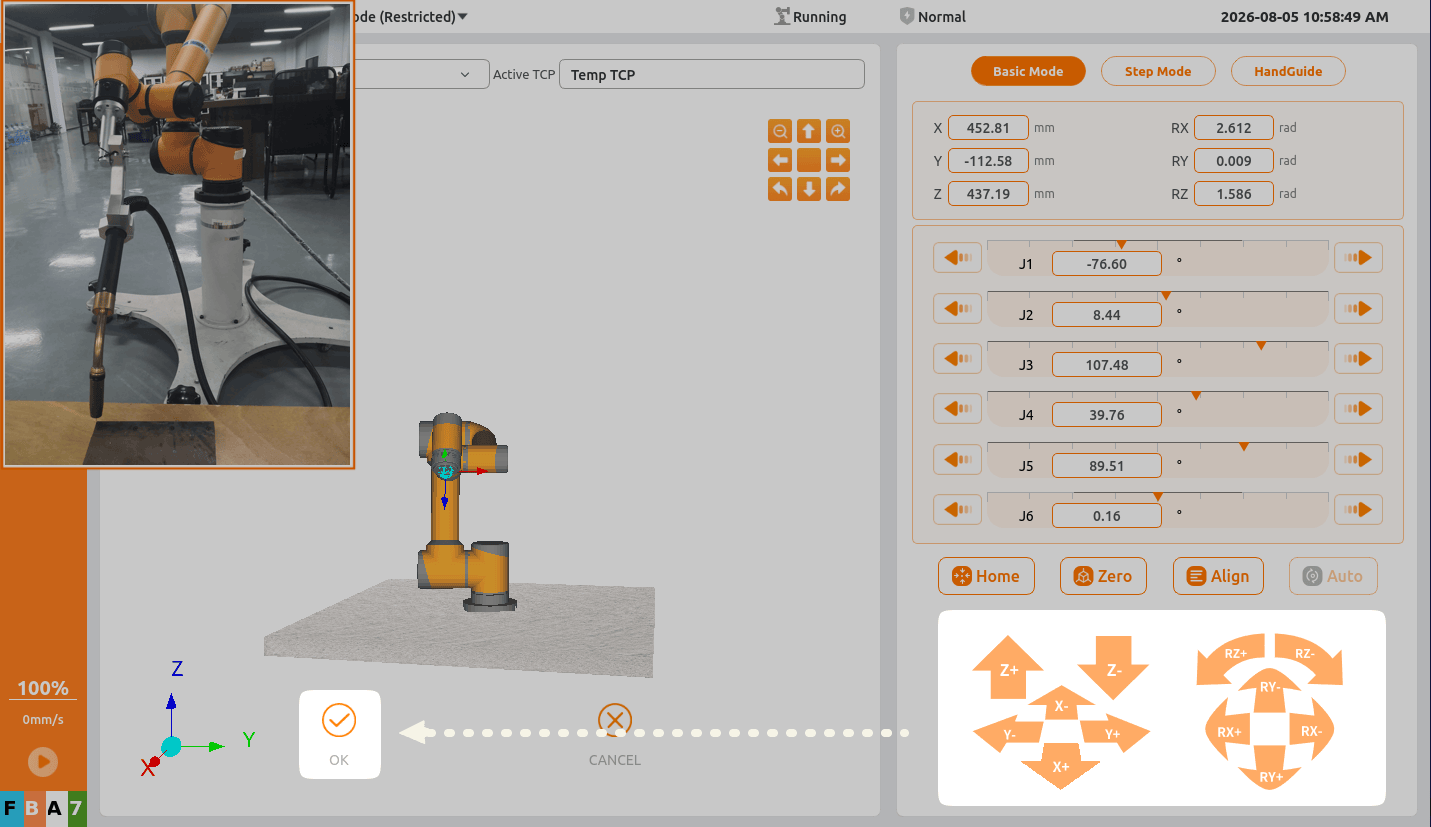
After all four points have been set, click
Setto exit theTeach TCP Positionwizard and view the TCP offset from the flange center calculated by the system.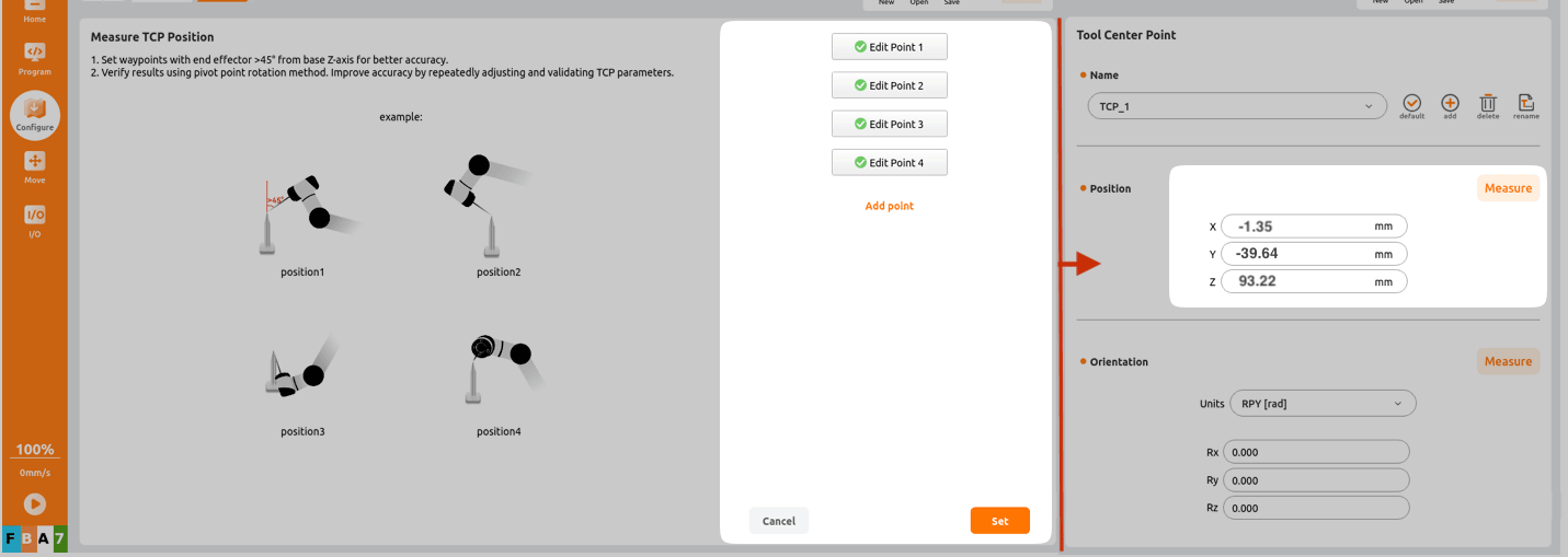
4.2 Teaching the TCP Orientation
Click
Orientation > Measureto enter theTeach TCP Orientationwizard.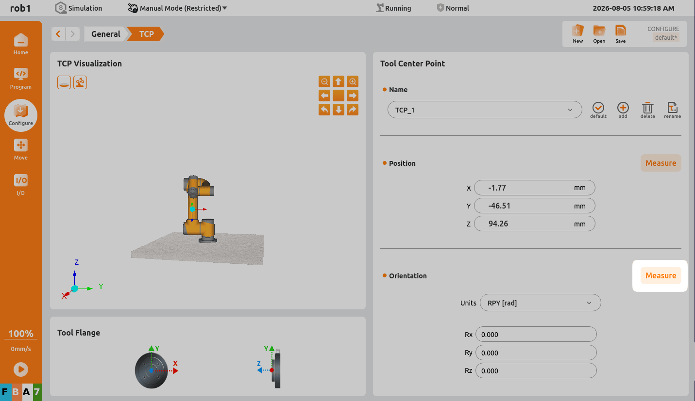
Select a coordinate system, then click
Set Pointto enter the teaching interface.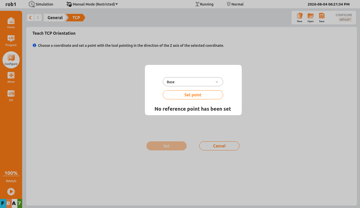
Adjust the tool orientation so that it aligns with the Z-axis of the selected coordinate system. At this point, the TCP coordinate axes will align with those of the selected coordinate system. Click
Confirmto return to theTeach TCP Orientationwizard.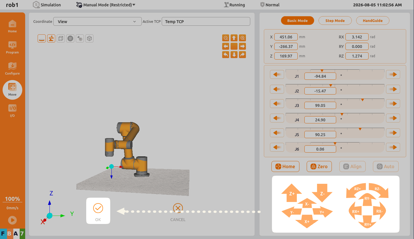
Review the orientation calculated by the system, then click
Setto exit theTeach TCP Orientationwizard.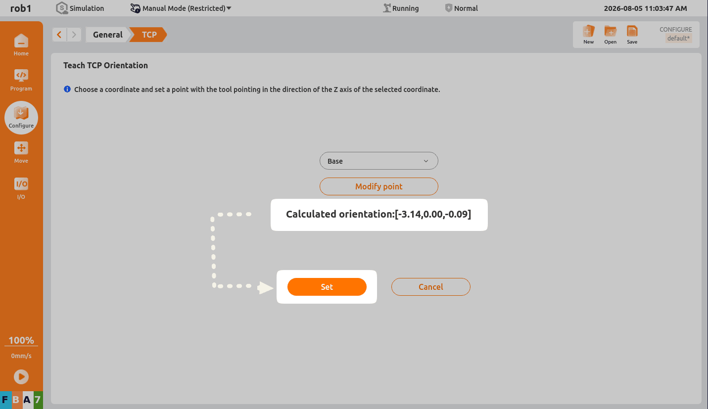
The result calculated by the
Teach TCP Orientationwizard is automatically filled in theOrientationparameter.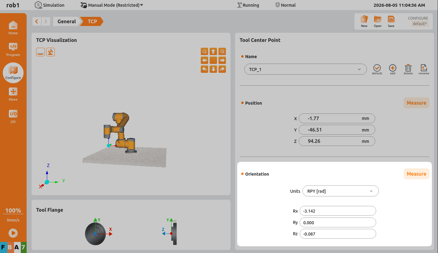
4.3 Applying the New TCP Configuration
Click
Defaultto activateTCP_1. Switch to theMovementinterface to verify thatTCP_1is now in use.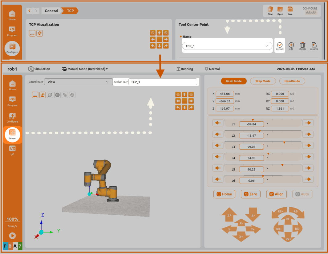
Click
Saveto save the configuration.
5 Causes of Poor TCP Accuracy
The primary factors affecting TCP calibration accuracy are:
- The robot arm's absolute positioning accuracy.
- The alignment accuracy of the taught points during TCP calibration.
注意
Before leaving the factory, AUBO robots undergo kinematic calibration and absolute positioning accuracy testing, achieving sub-millimeter-level absolute positioning accuracy.
6 Methods for Improving TCP Calibration Accuracy
The following methods can be used to improve TCP calibration accuracy:
- Preheat the robot: After powering on the robot, move each joint through a small range of motion (typically about 5°) before performing TCP calibration. This allows the robot to reach a stable operating state and helps eliminate mechanical errors caused by a cold start.
- Optimize the calibration configuration: Calibrate the TCP using a robot configuration that closely resembles the actual working configuration. Perform the calibration within the robot's dexterous workspace whenever possible, and avoid calibrating near singularities or joint limits.
- Improve the accuracy of each teaching point: Perform more precise calibration for each tool position. Repeat the calibration several times and verify that the positional errors of the tool remain consistent and are within the same order of magnitude.
- Increase the number of calibration points: Use additional calibration points when calibrating the tool position to improve the accuracy of the Tool Coordinate System origin.
- Optimize orientation calibration: Perform more precise calibration of the tool orientation. Auxiliary tools, such as a sleeve (to ensure that the robot arm moves along the tool coordinate axes), may be required to assist with orientation calibration.
- Fine-tune the calibration data: After completing the basic calibration, verify the calibration results using the methods described in 3 TCP Accuracy Verification Methods. Fine-tune the TCP data based on the verification results, then repeat the verification until the required accuracy is achieved.
If the above methods cannot satisfy the required accuracy, consider the following advanced measures:
- Contact the robot manufacturer for professional calibration.
- Define different Workpiece Coordinate Systems for different robot configurations to compensate for the robot's absolute positioning accuracy.
7 Q&A
7.1 The end effector is concentric with the end of the robot arm. In theory, only the Z-axis should have a value. Why do the calibrated X and Y values also have values?
The reasons are as follows:
- The tool may have manufacturing errors.
- Errors may occur when aligning the taught points during TCP calibration.
- Although the robot has undergone kinematic calibration, absolute positioning errors still exist.
Any of the above factors may cause a TCP that theoretically should have only a Z-axis offset to also have X- and Y-axis offsets after calibration. Use the methods described in 3 TCP Accuracy Verification Methods to determine whether these offsets are within an acceptable range.
7.2 What causes differences in calibration accuracy?
See 5 Causes of Poor TCP Accuracy.