
Line Laser Plugin User Manual
1. Plugin Installation
1.1 Downloading the Plugin
Download address: contact the relevant technical personnel to obtain the plugin.
1.2 Installing the Plugin
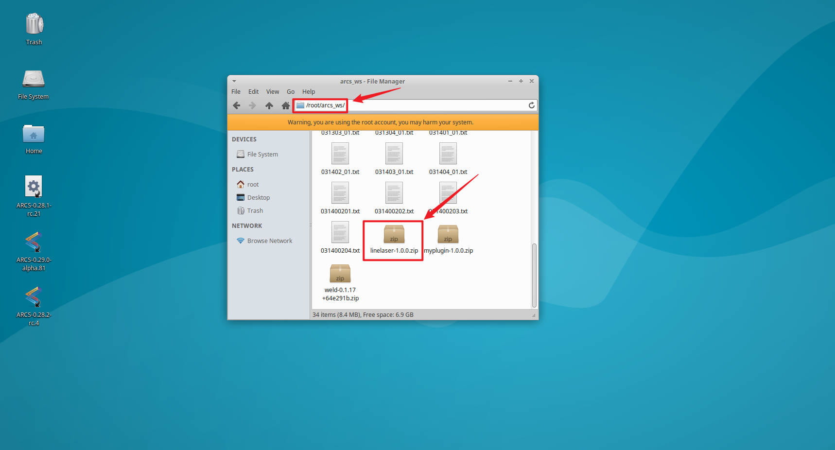
Place the plugin in the specified directory.
Open the software and go to Home -> Settings -> System -> Plugins, then click Add.
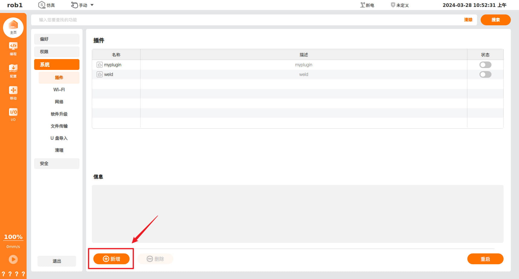
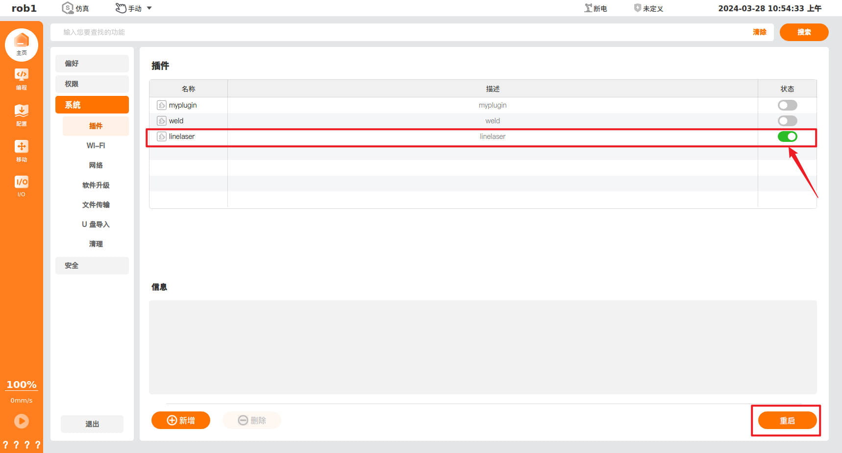
Select the corresponding plugin, then restart.
Open the plugin.
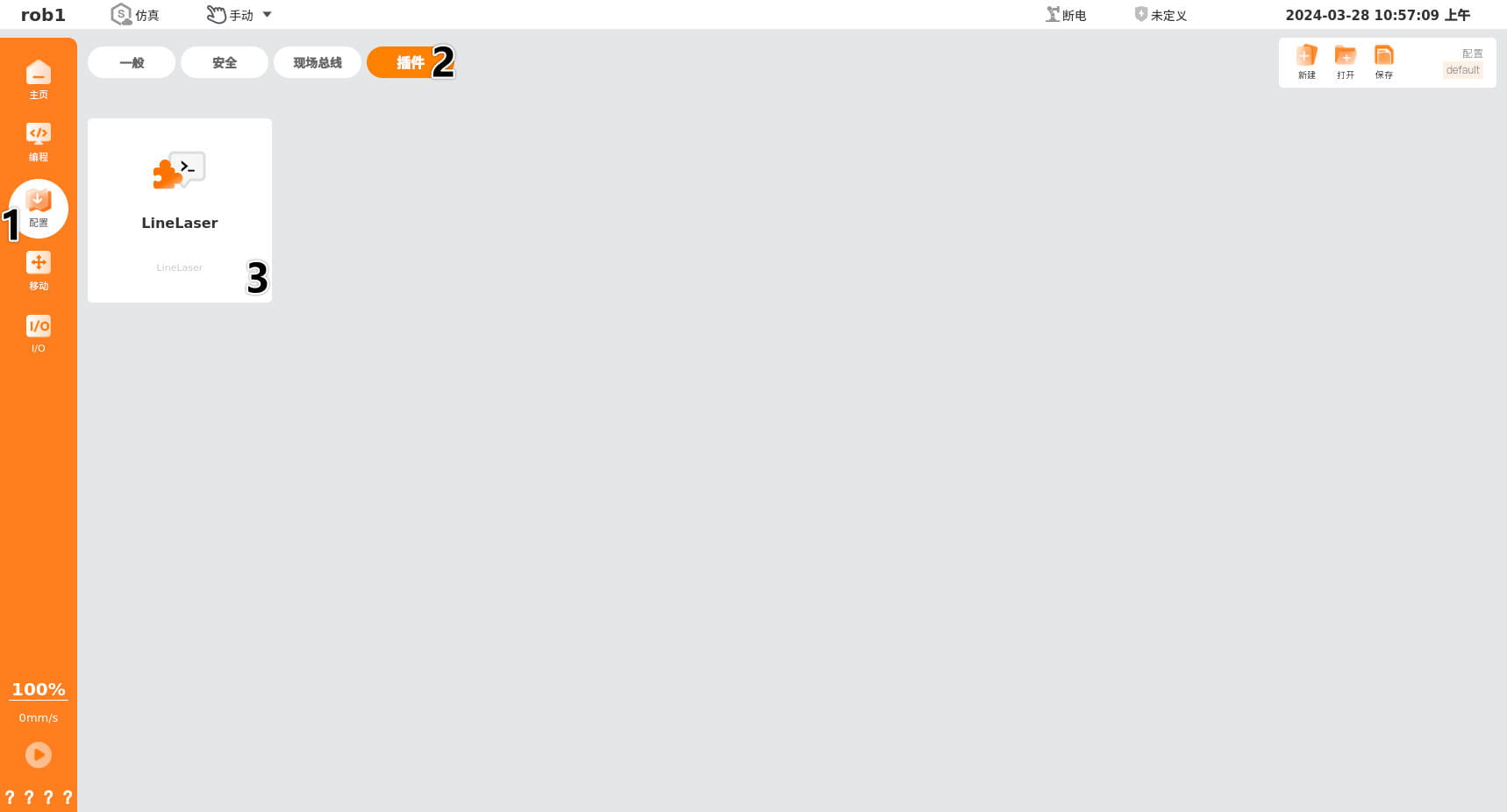
Plugin interface.
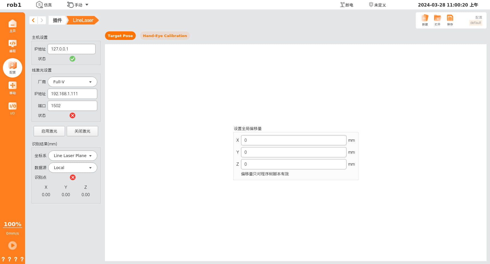
The plugin is installed successfully.
2. Sensor Installation
2.1 Installation Diagram
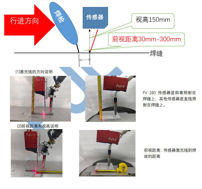
The installation height is about 150 mm. The horizontal distance between the TCP and the laser line is called the look-ahead distance, generally in the range of 30 mm-50 mm. The longer this distance is, the greater the influence of welding deformation.
2.2 Hand-Eye Calibration
Interface: different manufacturers correspond to different Modbus port numbers — Quanshi corresponds to 502 and Mingtu corresponds to 1502. This tutorial takes Suzhou Quanshi as an example.
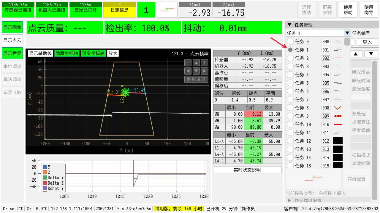
First, set the weld seam type in the sensor (select lap joint, which is more convenient to operate), select Task 1, and load it.
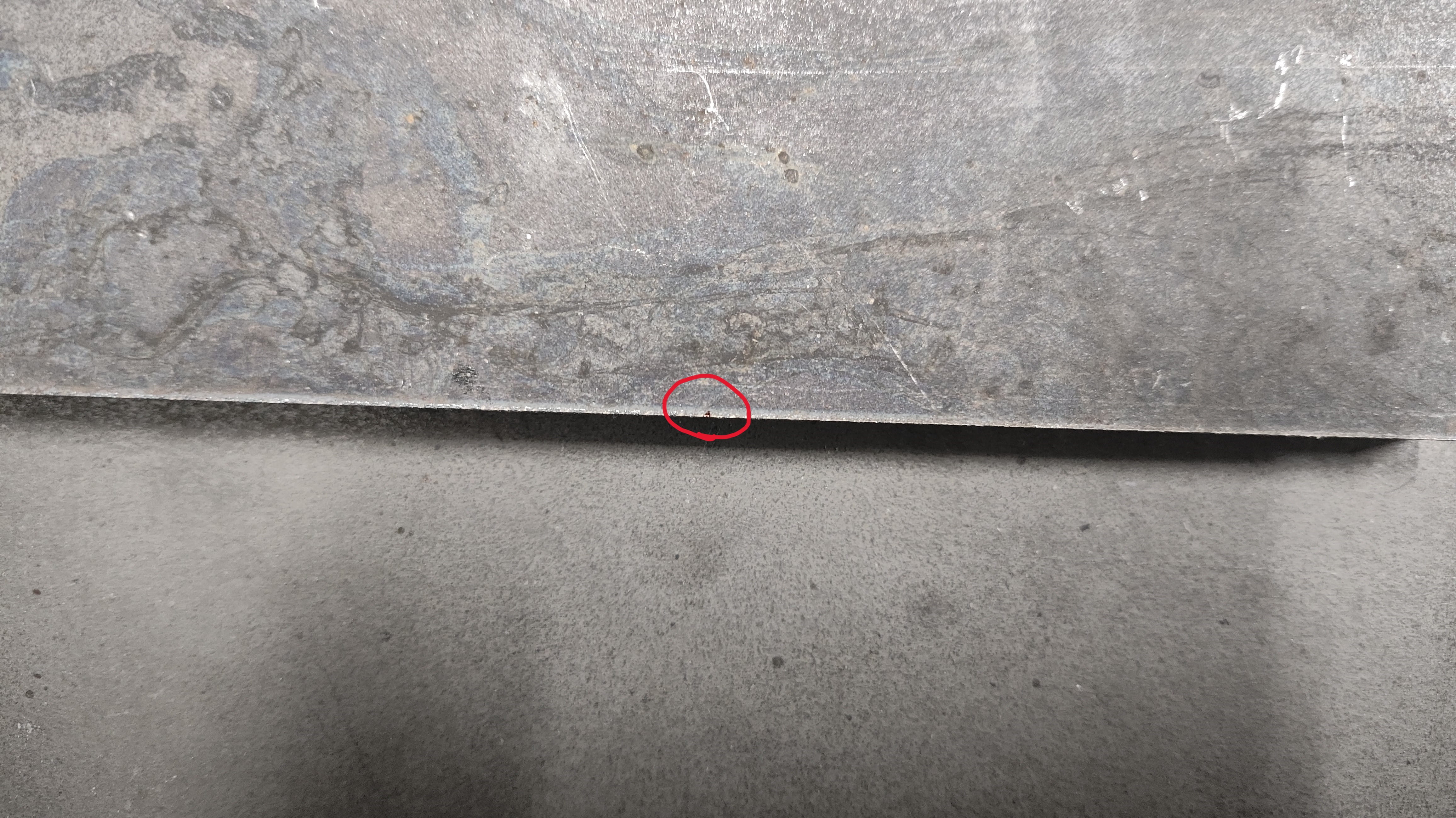
Then make a mark point on the corresponding weld seam, as shown below:
Hand-eye calibration process: record five poses in order from top to bottom on the far right side of the interface. Ensure that the sensor can recognize the weld seam point in all five poses, then calculate and save.
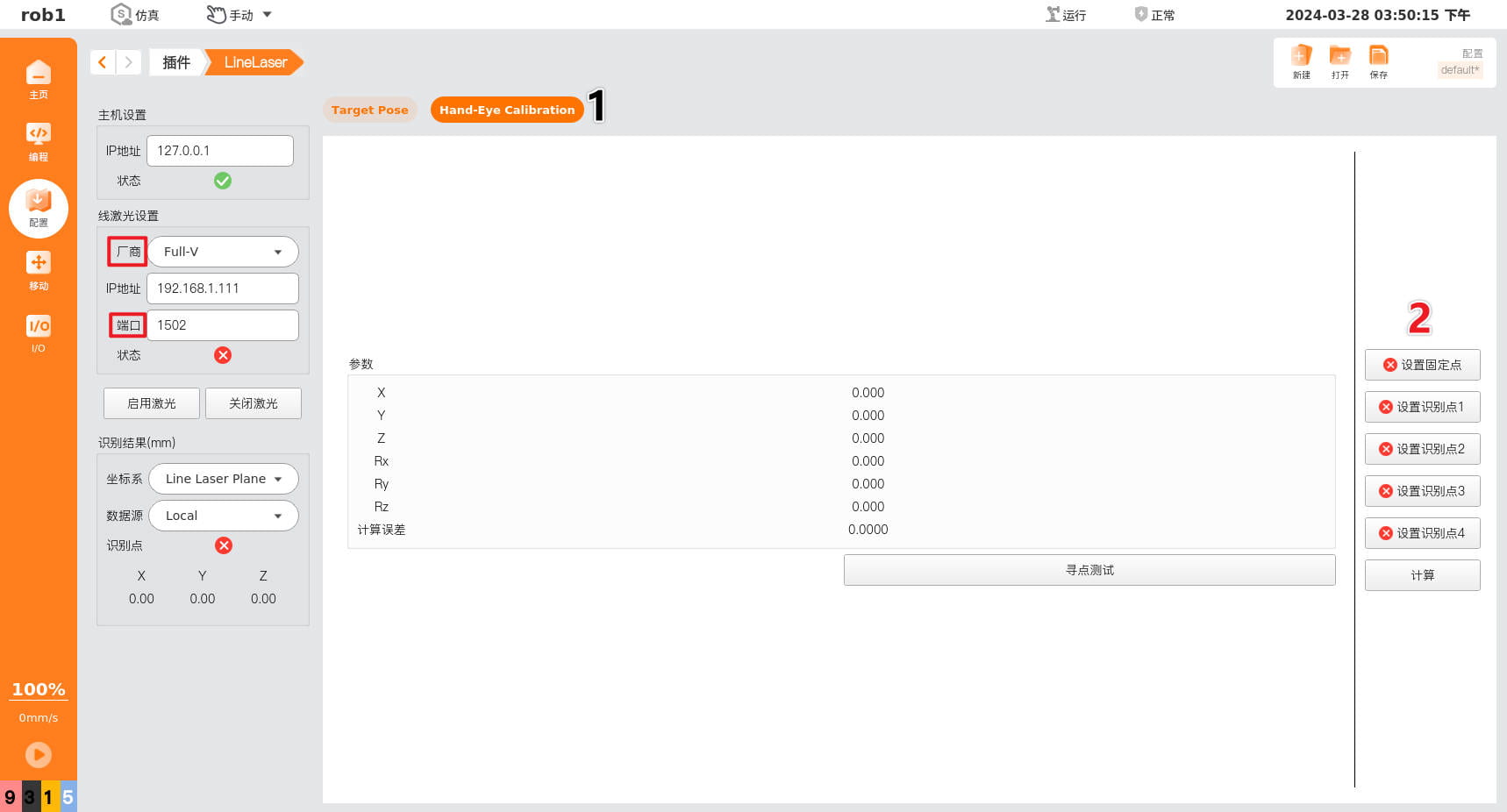
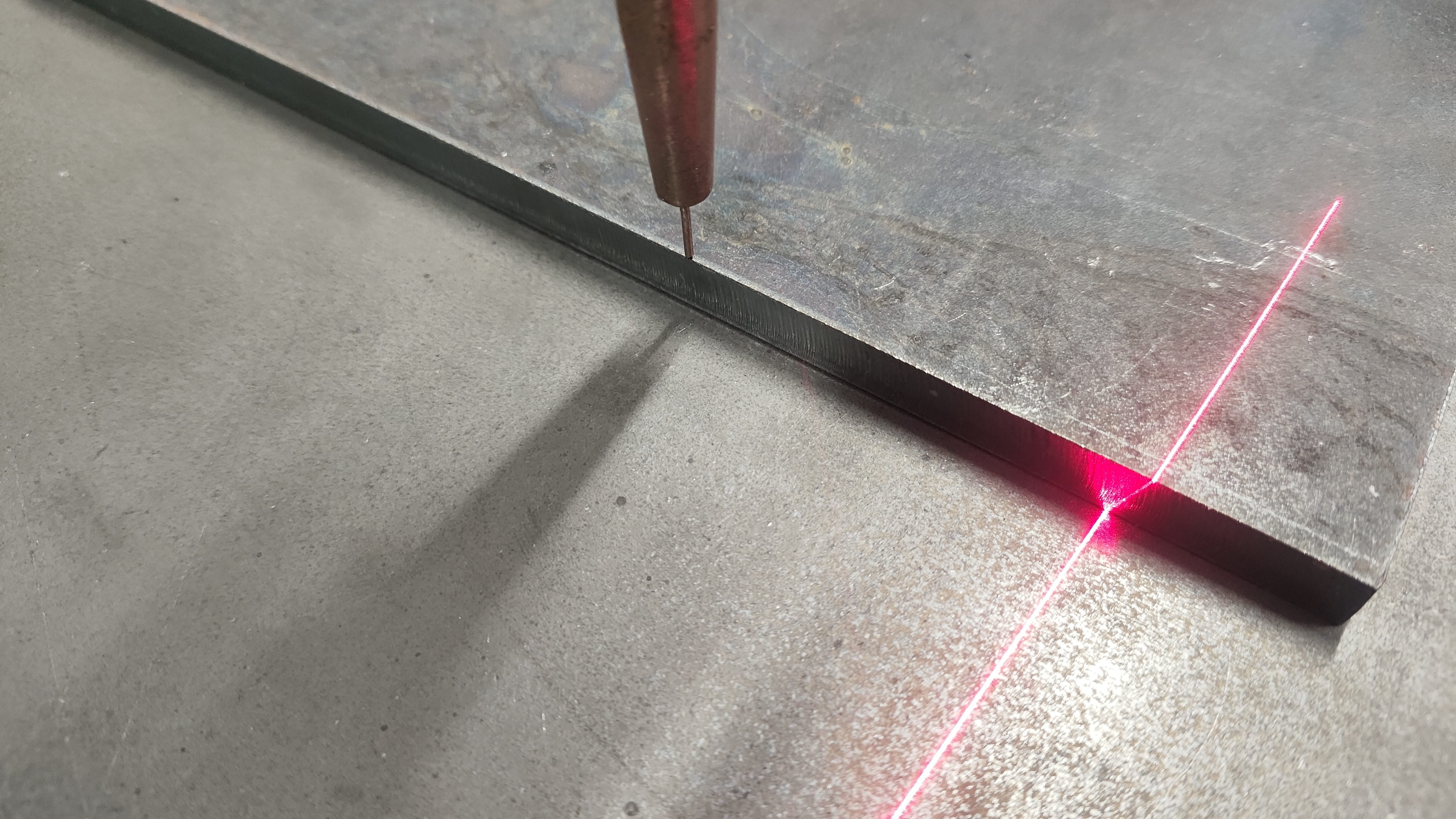
Start hand-eye calibration: click Set Fixed Point, and in the interface below point the TCP as precisely as possible at the weld seam mark point, as shown, then click OK.
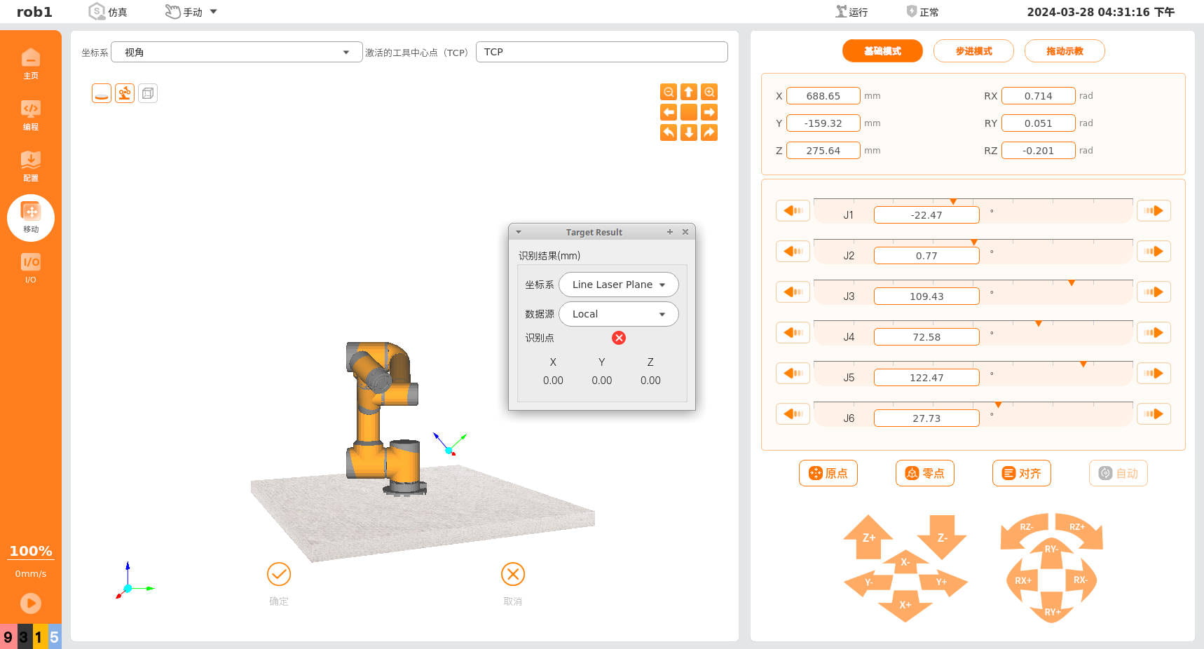
Then click "Set Recognition Point 1", move the robot arm in the interface so that the line laser shines on the weld seam mark point, and confirm.
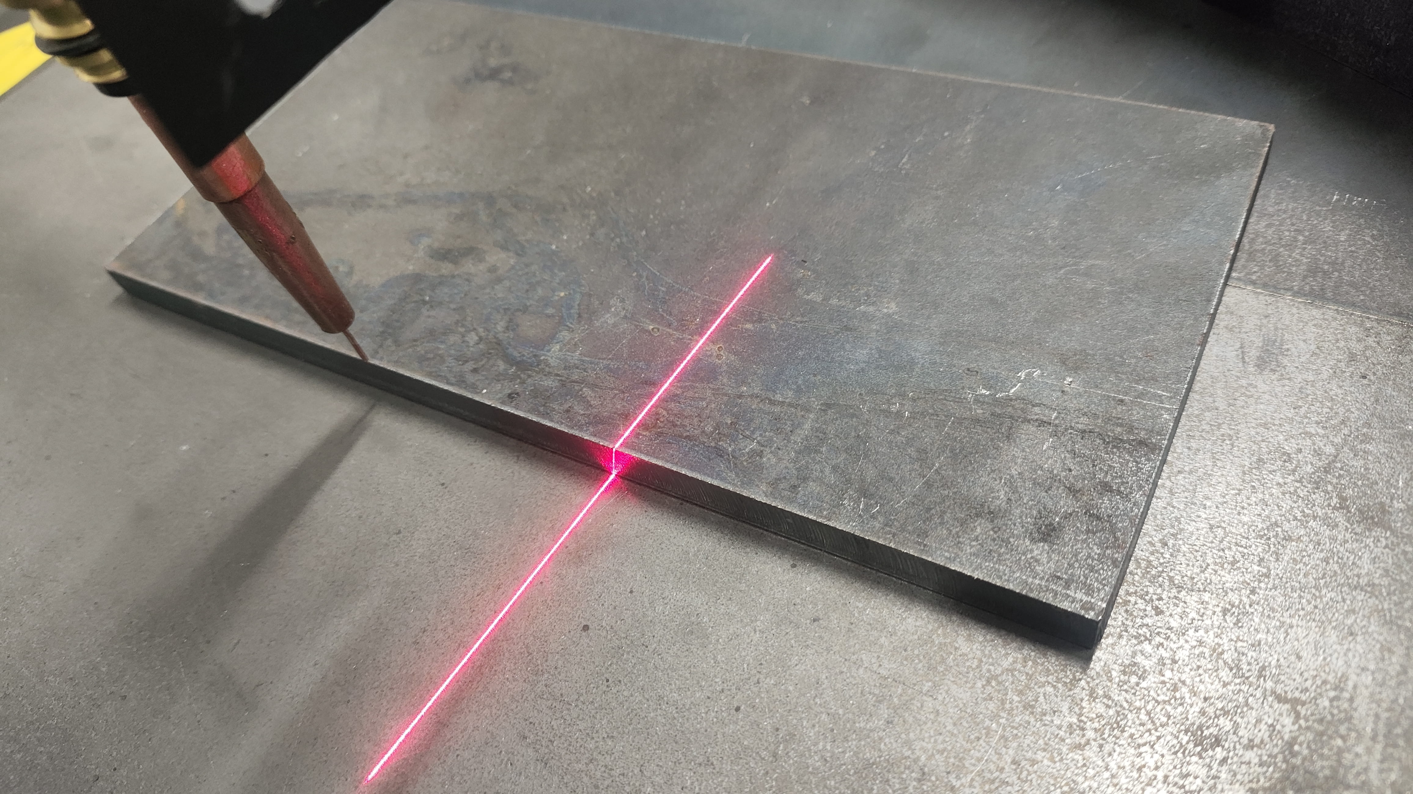
Then click "Set Recognition Point 2", move the robot arm laterally, keeping the height unchanged while adjusting forward and backward, to ensure the line laser shines on the weld seam mark point, and confirm.
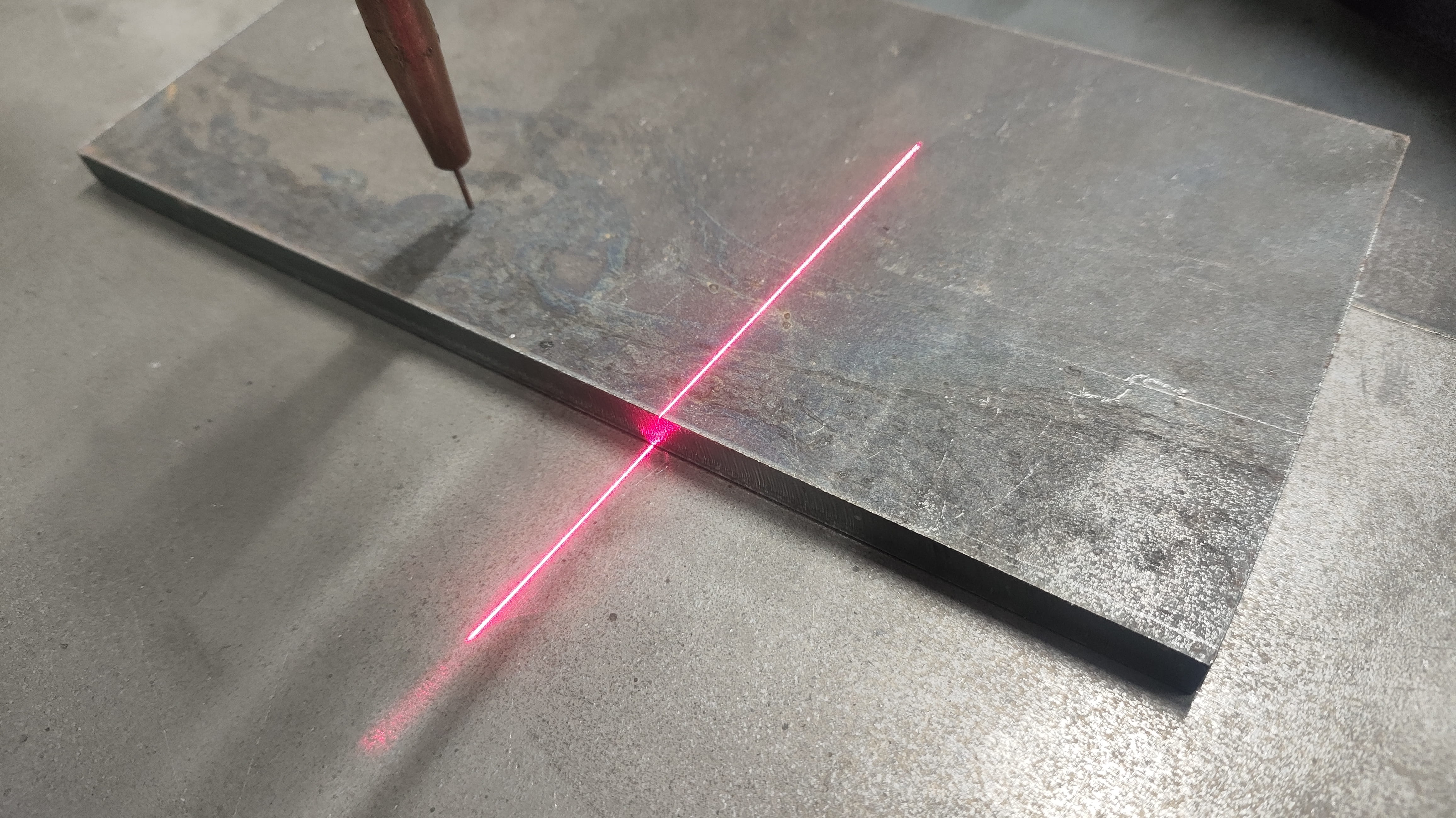
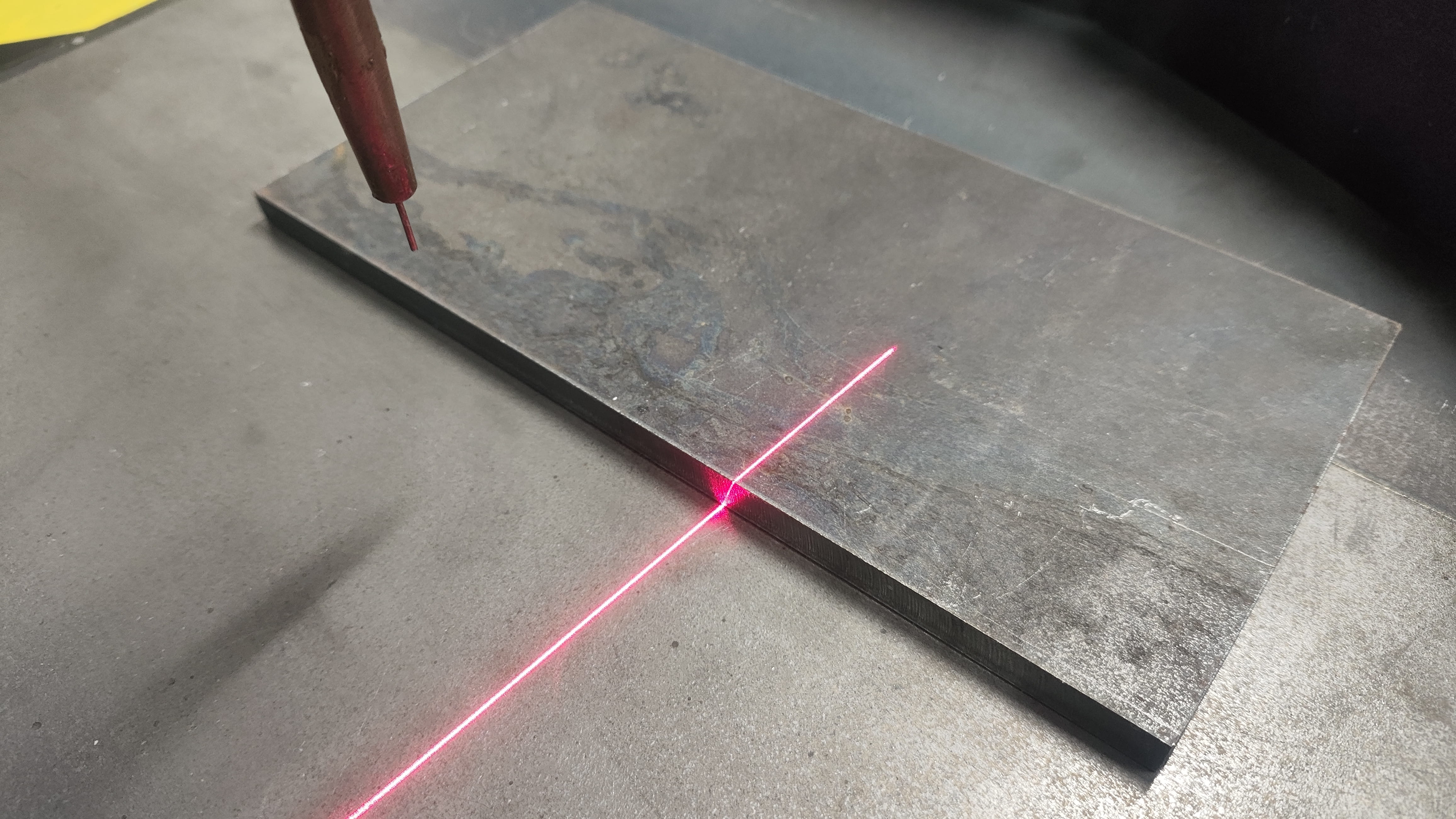
Click "Set Recognition Point 3", raise the robot arm a certain distance, and move it forward and backward to ensure the line laser shines on the weld seam mark point, and confirm.

Click "Set Recognition Point 4", move the robot arm, keeping the height unchanged while adjusting forward and backward, to ensure the line laser shines on the weld seam mark point, and confirm.
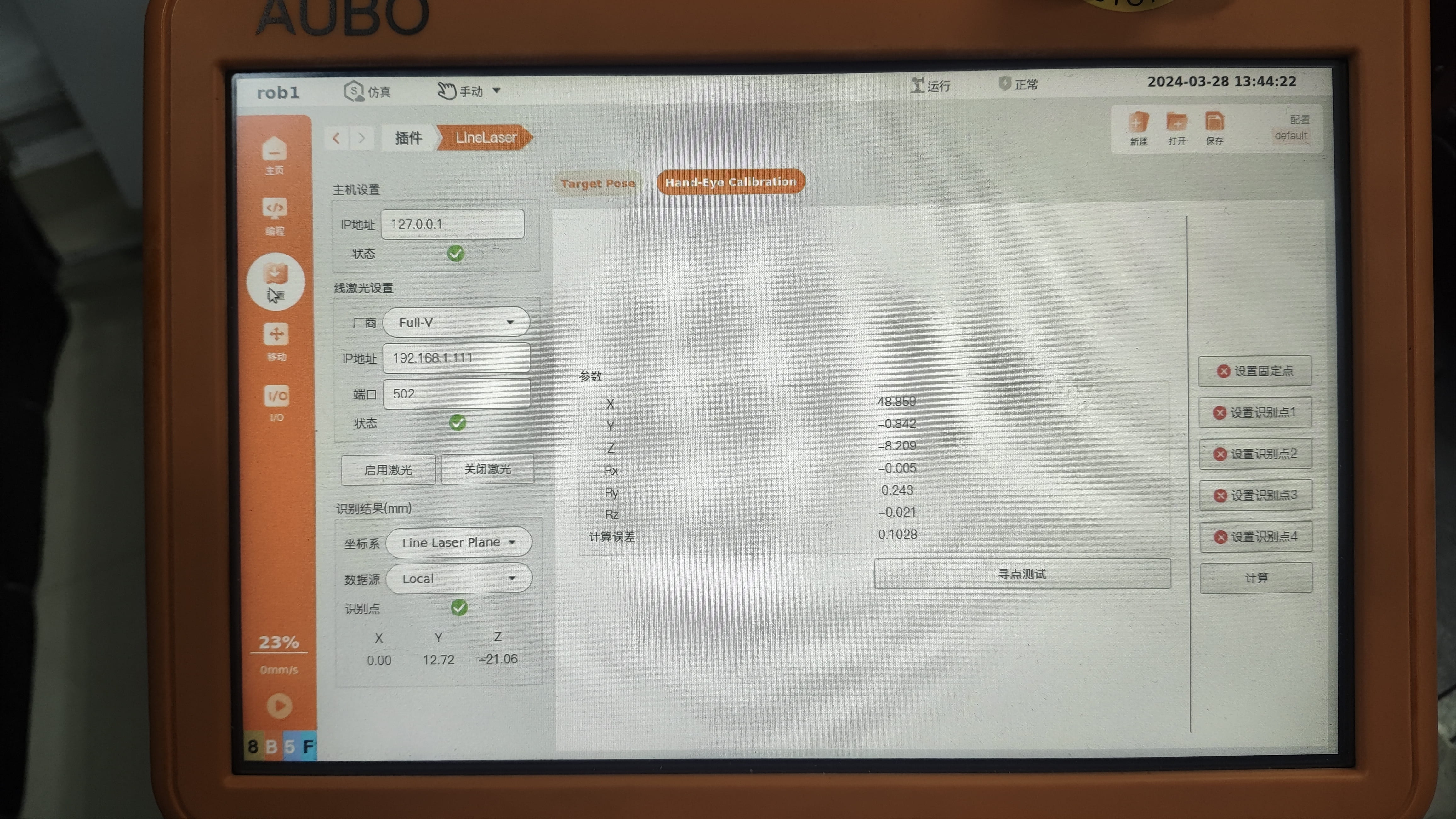
Finally, click "Calculate"; the result is displayed in the middle. A calculation error below 0.5 is generally acceptable. Click Save Result at the top right. Hand-eye calibration is now complete.
3. Program Node Introduction
3.1 Laser Positioning
The function of this program node is to set the sensor task number, obtain the recognized weld seam coordinate point (x0,y0,z0), and combine it with the (Rx0,Ry0,Rz0) of "waypoint_0" to form the global variable "expect_0" for subsequent use.
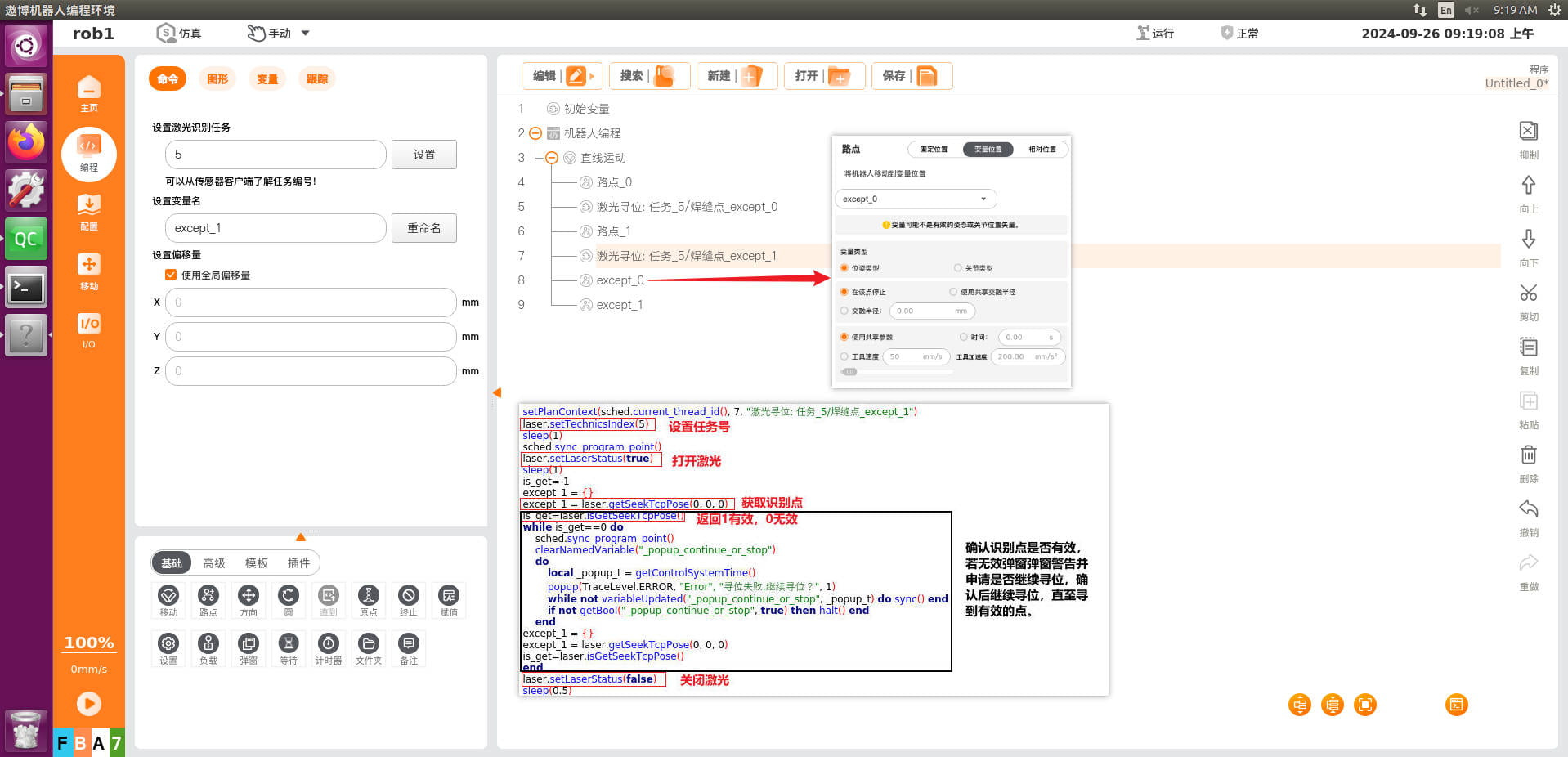
3.2 Laser Searching
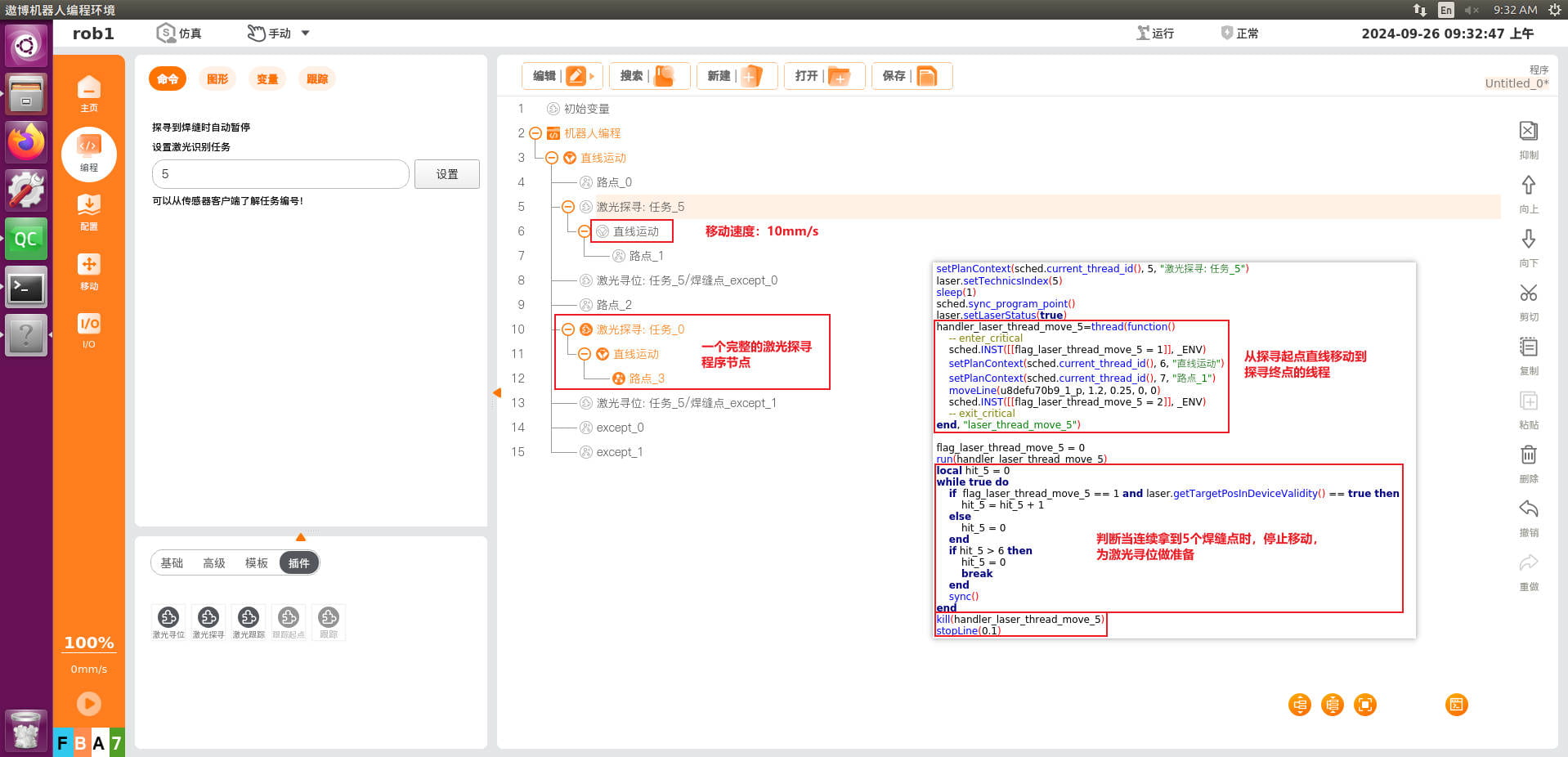
The function of this program node is to have the line laser sweep from "waypoint_0" to "waypoint_1", stopping when it reaches the weld seam point. It must be used together with laser positioning; when it stops, it obtains the scanned point. The task number must be set first.
3.3 Laser Tracking
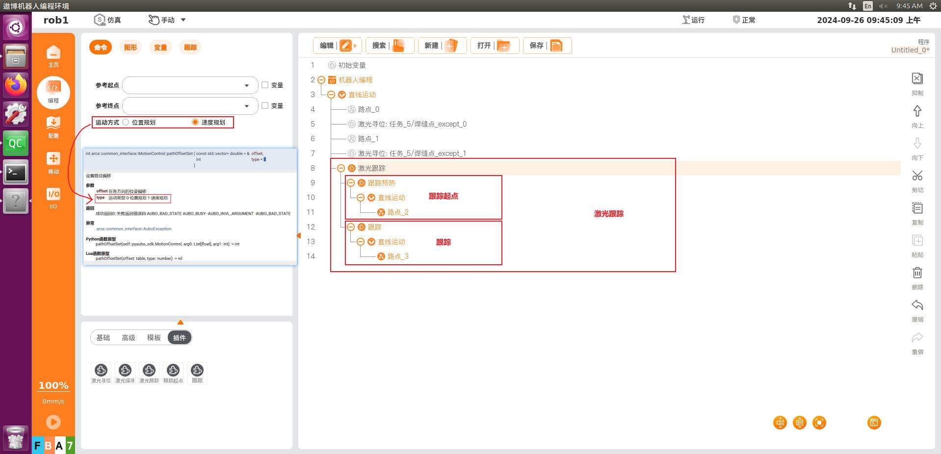
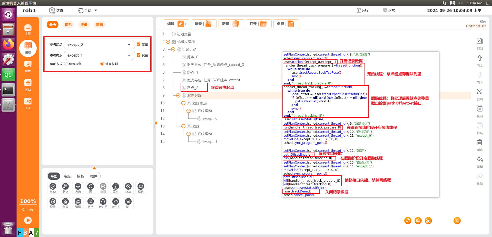
The function of this program node is divided into two parts. From "waypoint_2" to "variable_0" is the tracking warm-up phase; in this phase, the region swept by the laser should include the weld seam start point, and the running thread of this phase then stores the recognized points in a queue. The next phase is the tracking phase, the main phase of the node, during which enabling begins, the robot takes points from the queue, and performs tracking. "waypoint 4" is the start point of the tracking warm-up, generally obtained by teaching; "variable_0" and "variable_1" are the start and end points of the weld seam, generally obtained by positioning.
Note:
1. The speed for laser searching is 6-10 mm/s, generally set to 8 mm/s.
2. The speed in the tracking warm-up phase is 6-15 mm/s, generally set to 10 mm/s.
3. The speed for tracking and actual welding is 6-10 mm/s, generally set to 8 mm/s.