Profinet Slave User Guide
1 Environmental preparation for Profinet configuration
1.1 Environmental preparation
Download data packet
Install the smart200 debugging software SETP7;
GDS file
gsdml-v2.31-arcs-ICM-20240529.xml;
Hardware
Siemens
s7-200 smart, robot arm body, laptop, network cable, HUB or switch;Software version
- Software after v0.29.5-rc.22 and v0.31.0-rc.27 have been integrated into ARCS software, without the need for manual installation;
- For software of previous version, Profinet plug-in shall be installed. To update the plug-in version, please contact Liu Hui in the Software Department;
1.2 Hardware wiring
Connect the PLC, the controller and the local computer to the same network through the switch;
1.3 Profinet software installation and configuration
1.3.1 Installing pn_server
Method 1: Software after v0.29.5-rc.22 and v0.31.0-rc.27 have been built-in with pn protocol stack, without the need for manual installation;
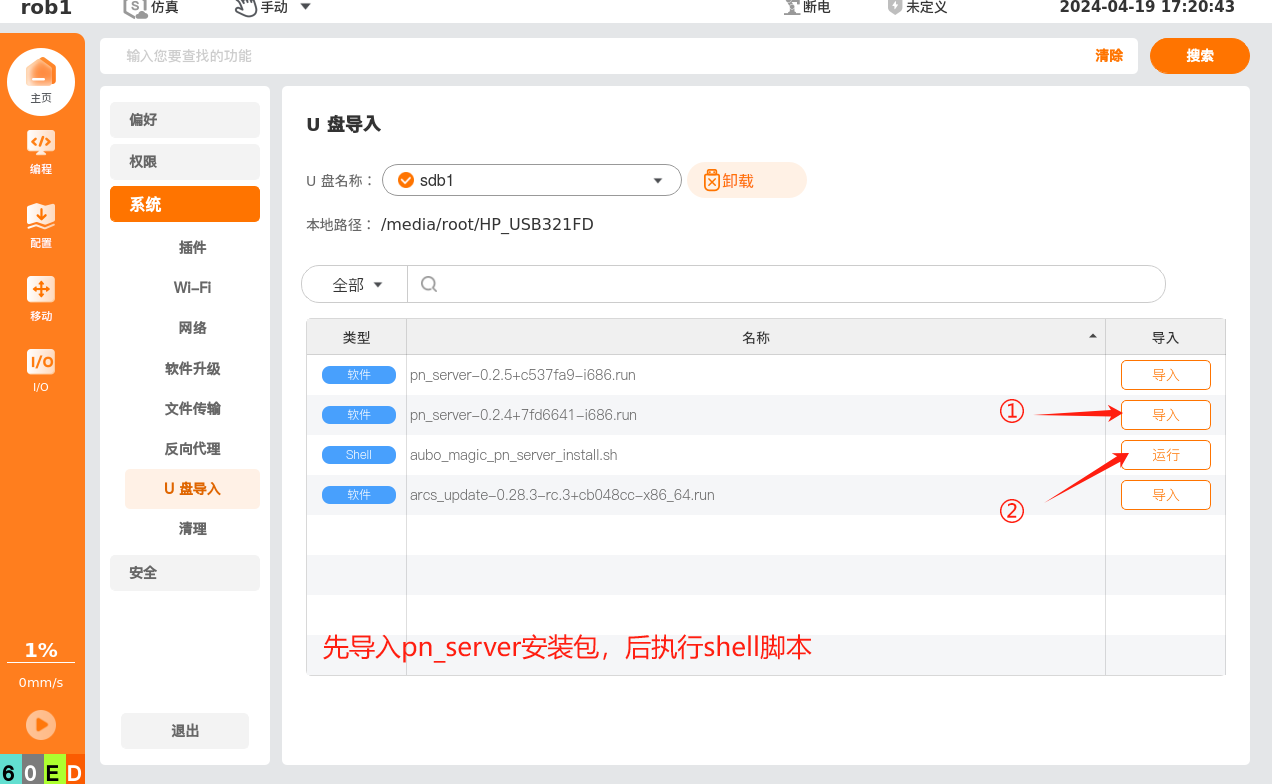
Method 2: Copy the required files, as listed below, in the root directory of the USB flash drive, and then import them through the teach pendant, as shown in the following figure:
- pn_server-x.x.x.run
- aubo_magic_pn_server_install_v1.0_20240422.sh
1.3.2 Checking for the successful completion of installation
Turn on the Profinet button in ACRS and observe the current status of Profinet IO; Disconnected or Connected indicates a normal startup.
Run systemctl status pn_server.service to view:
Current pn_server self-starting state (
enabledindicates the pn_server is in self-starting process);Current version of
pn_server;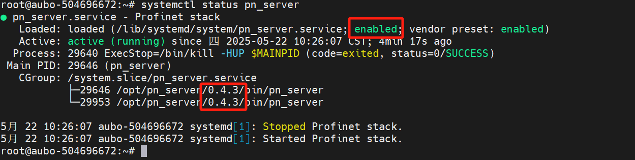
When
profinetplug-in is manually installed, the version number will be displayed, and when pn software protocol stack is built in ARCS, only the current software version number is displayed, as shown in the following figure;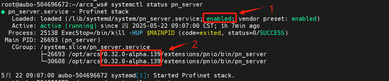
1.4 Profinet software test and verification
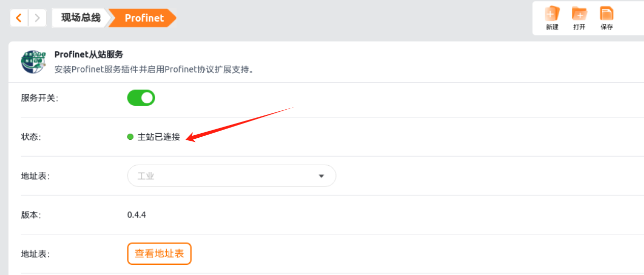
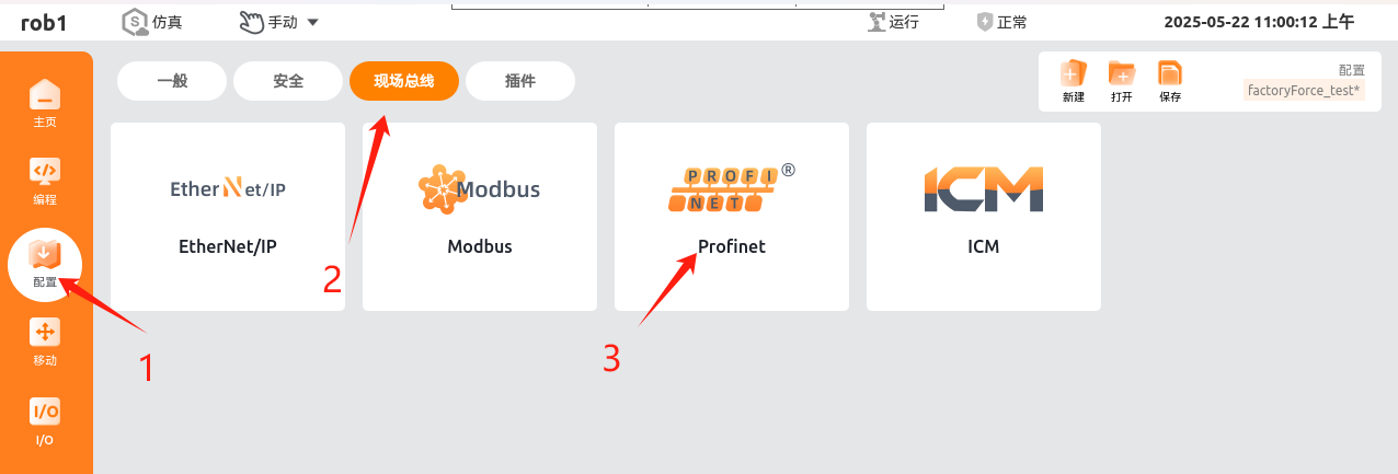
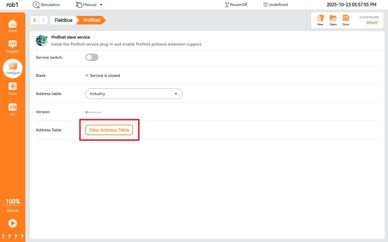
1.4.1 Opening Profinet slave
Click in turn according to the figure below to open the Profinet slave
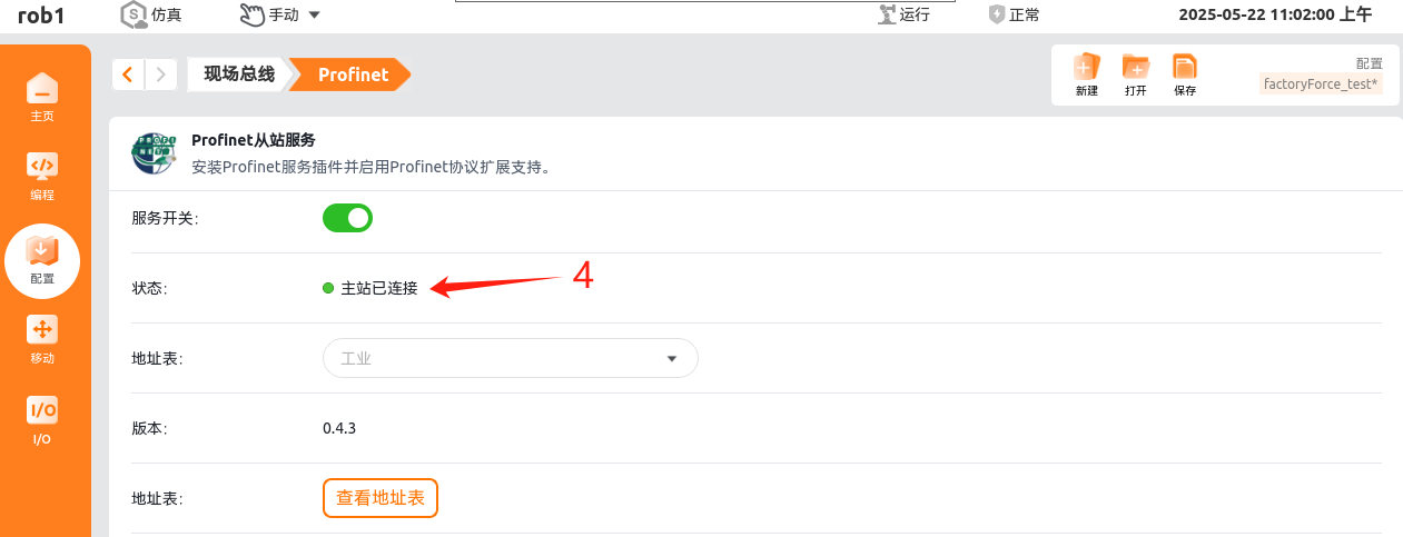
The following figure shows the status of correct connection; when it is not connected, the status indicator light turns yellow.
1.4.2 Connecting PLC to Profinet Slave
For the purpose of this Guide, s7-200 smart plc (hereinafter referred to as PLS) is taken as an example for explanation.
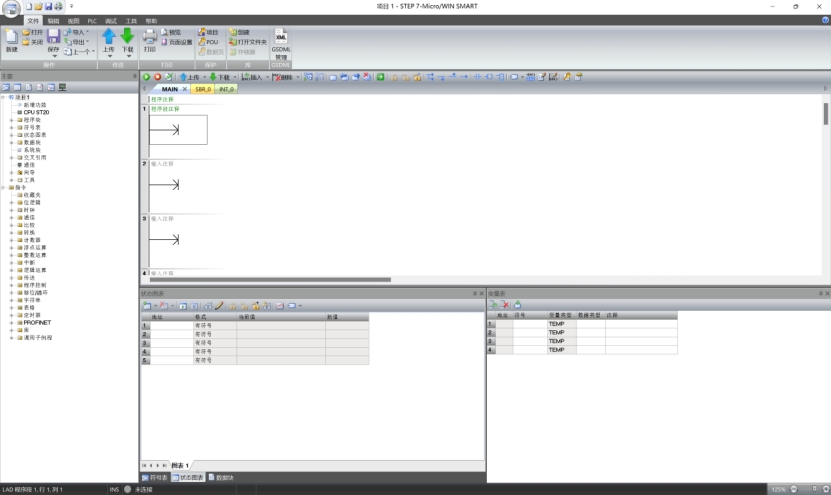
This PLC is programmed with STEP-7 Micro/WIN SMART, instead of the TIA Portal software used by S7-1200 PLC or the similar.
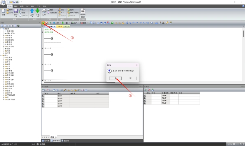
Open the software interface as shown in the figure below.
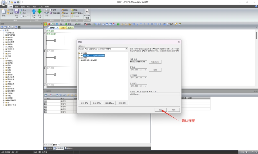
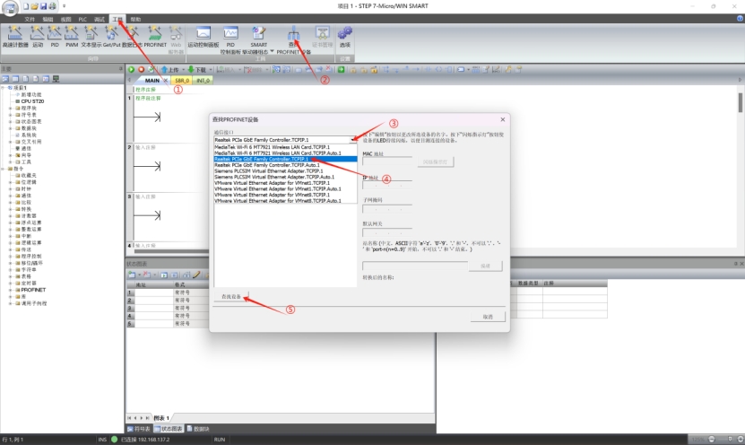
First, connect the computer and PLC to the same LAN, and click in turn according to the following figure to search for the PLC under the LAN.
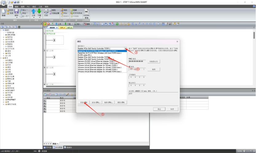
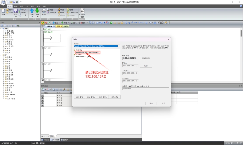
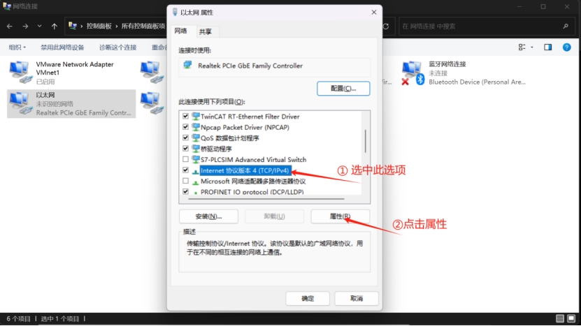
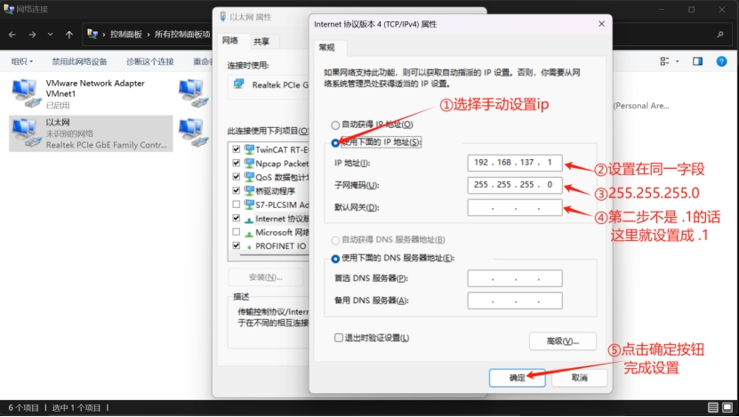
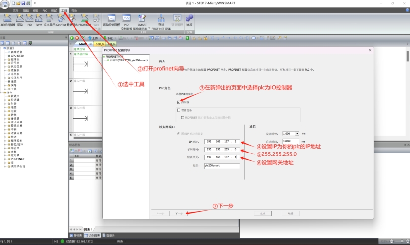
Considering that the PLC itself has an IP address, the computer is required to be configured with a fixed IP address in the same LAN to secure a successful connection. As an example in this Guide, the PLC is assigned with an IP address of 192.168.137.2, and connected to the PCIe network card (wired network card). In this case, the IP address of the wired network card shall be configured as 192.168.137.X, where X shall be greater than 0 and less than 256. Attention shall be paid that the IP address of the wired network card shall be different from that of the PLC. The specific instructions for configuring the IP address of network card are described as follows:
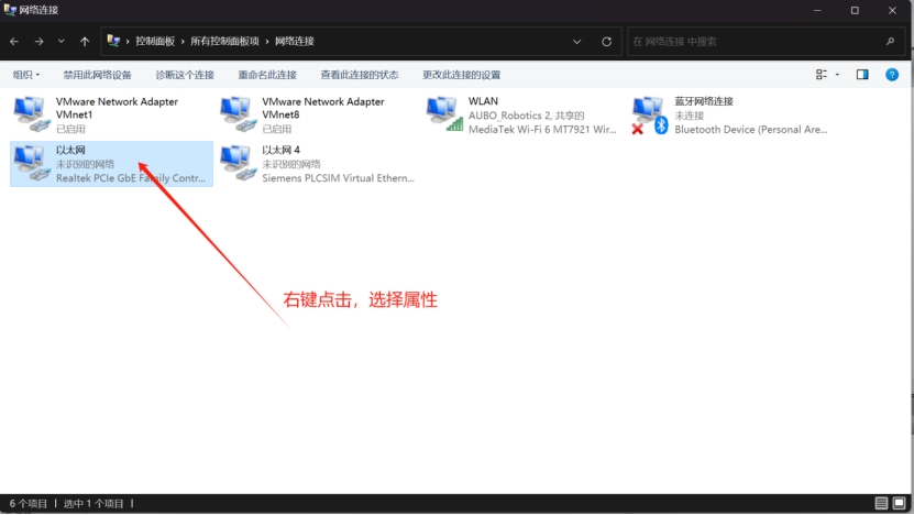
Press WIN+R to pop up the Run window, enter ncpa.cpl and press Enter to navigate to network connection settings
At this time, the PLC and the computer are under the same network segment, and can be connected normally.
Note: To change the PLC`s IP address, the PLC must be connected; and to connect the PLC, it must be in the same network segment;
Now the PLC can be connected normally.
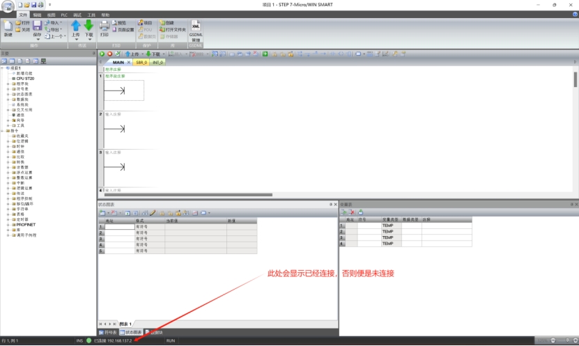
The status after connection is shown in the figure below.
1.4.3 Configuring program
First, import a GSD file (Generic Serial Device description File)
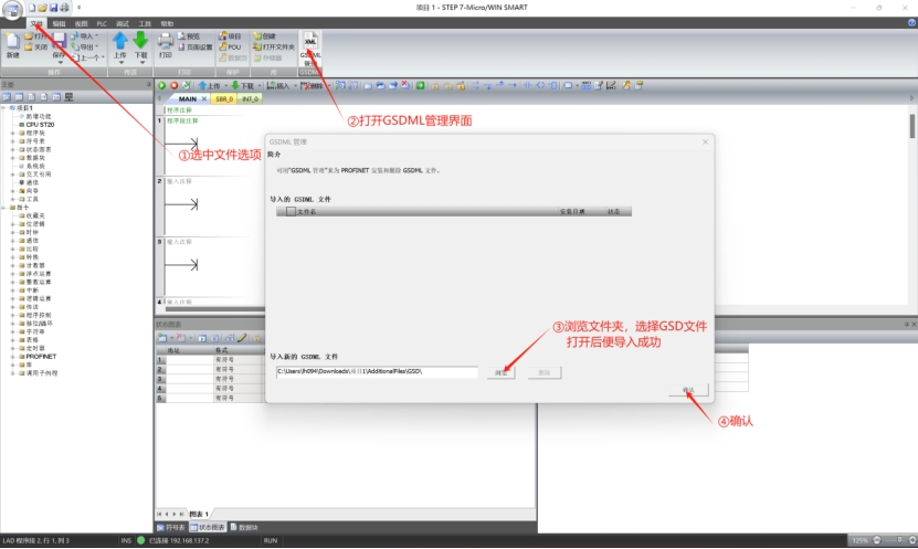
After the GSD file is imported successfully, configure the Profinet test program.
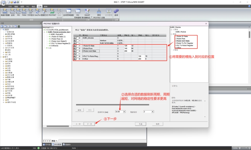
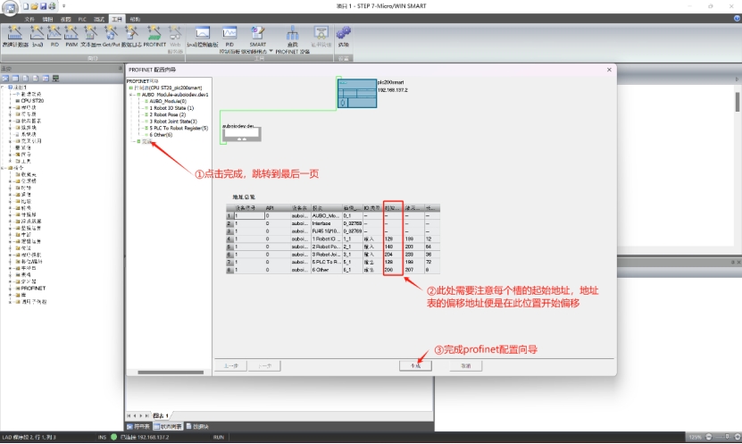
Then, the configuration of Profinet is completed. Save the program and click Download to download the program to the PLC.

Now your PLC has completed the Profinet wizard and the test program has been downloaded correctly; the Profinet slave of the robot has been opened correctly, and the robot, PLC and computer are in the same network segment of the same LAN.
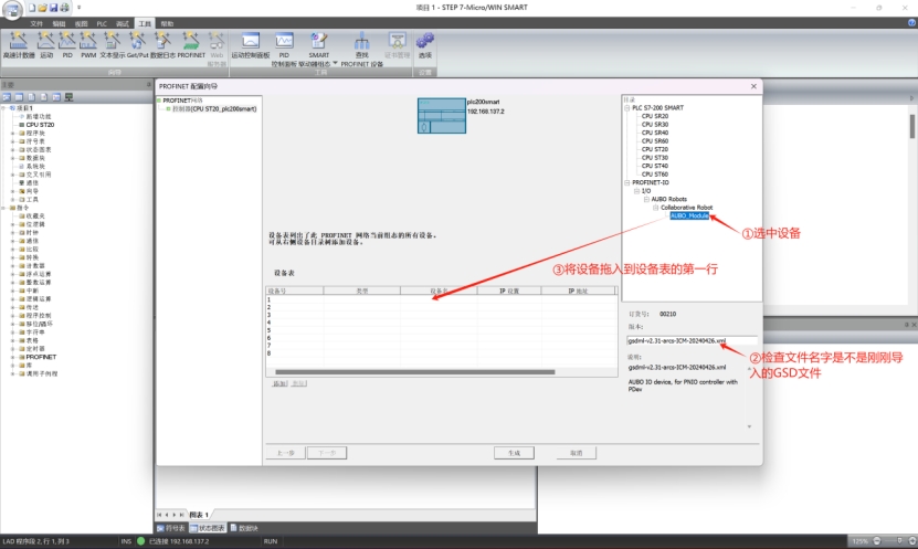
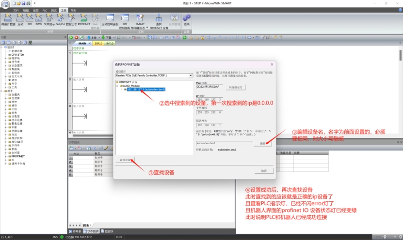
Search for Profinet device in the LAN
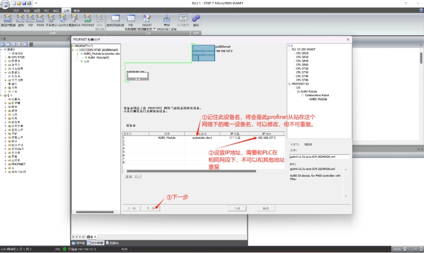
Then assign a name to the Profinet slave. Now, the PLC is in the correct connection status, as shown in the figure below.
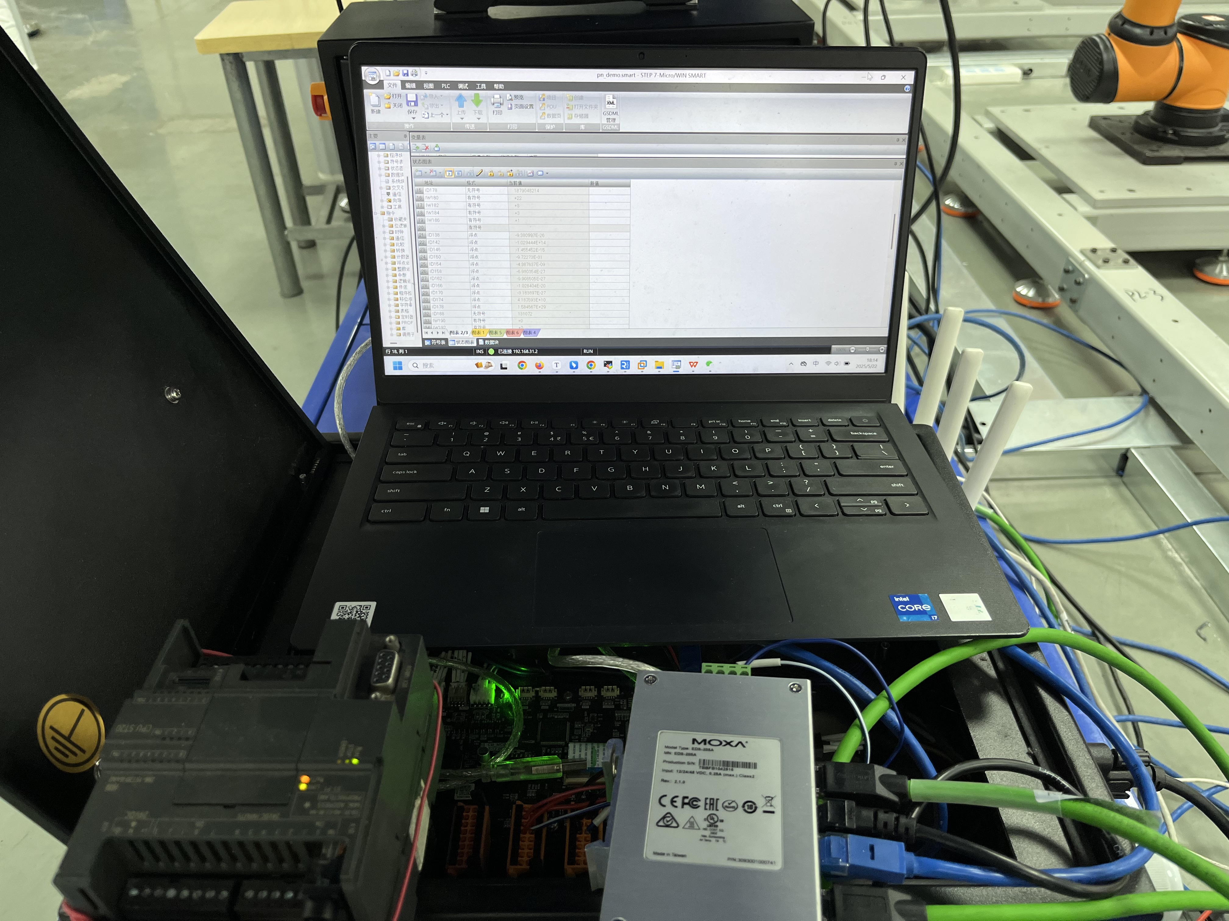
1.4.4 On-line monitoring of IP address signal
This step is designed to view the data of robot slots.
By checking the address table and the start address of the PLC, it is known that the IP address 190 of slot 2, with two bytes, represents the heartbeat of the slave. Therefore, in this User Guide, it is monitored for the purpose of explanation.
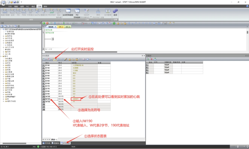
You may also set other IP addresses to monitor the change of data. If signal change is monitored, it indicates that the Profinet software communicates normally and can be used.
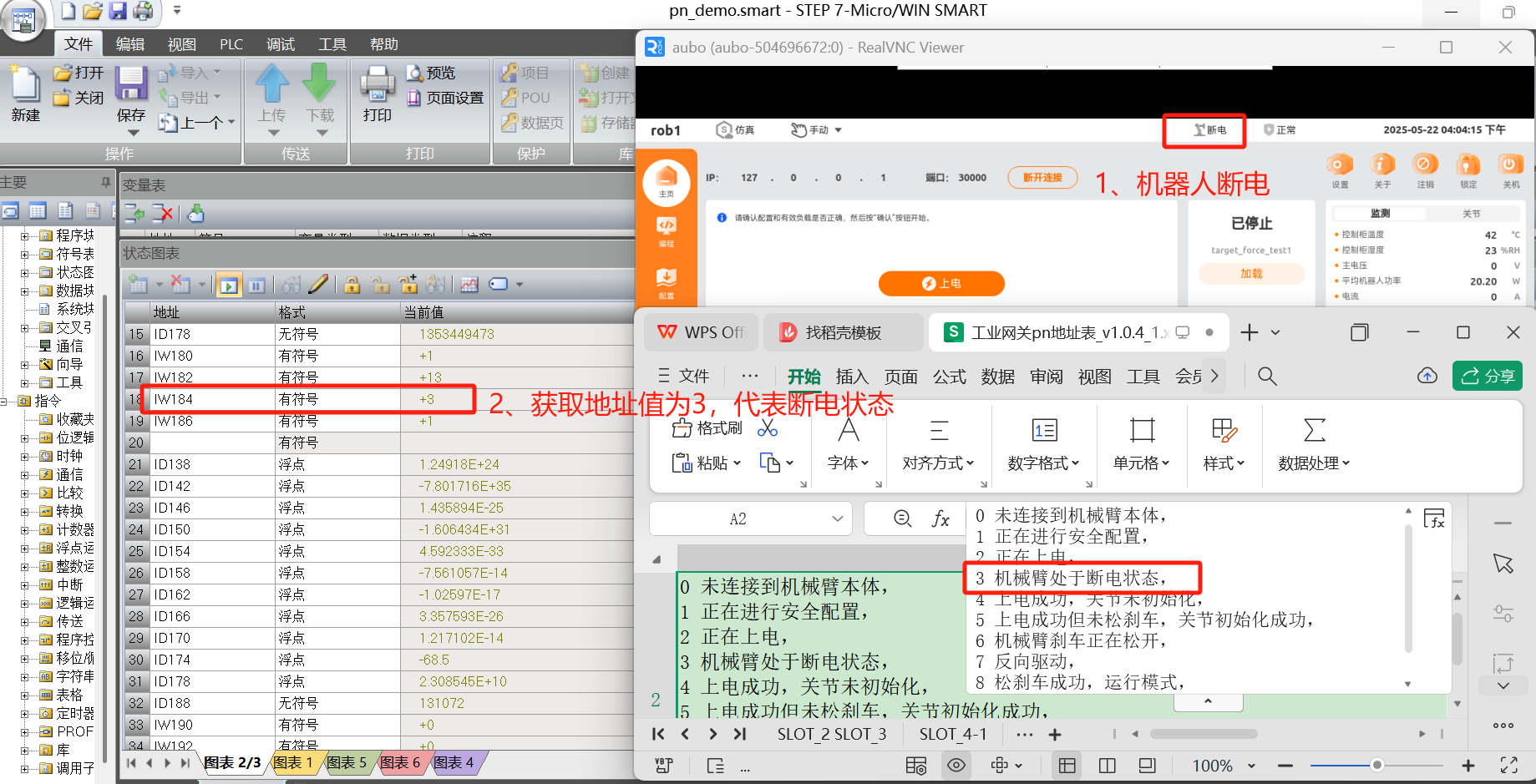
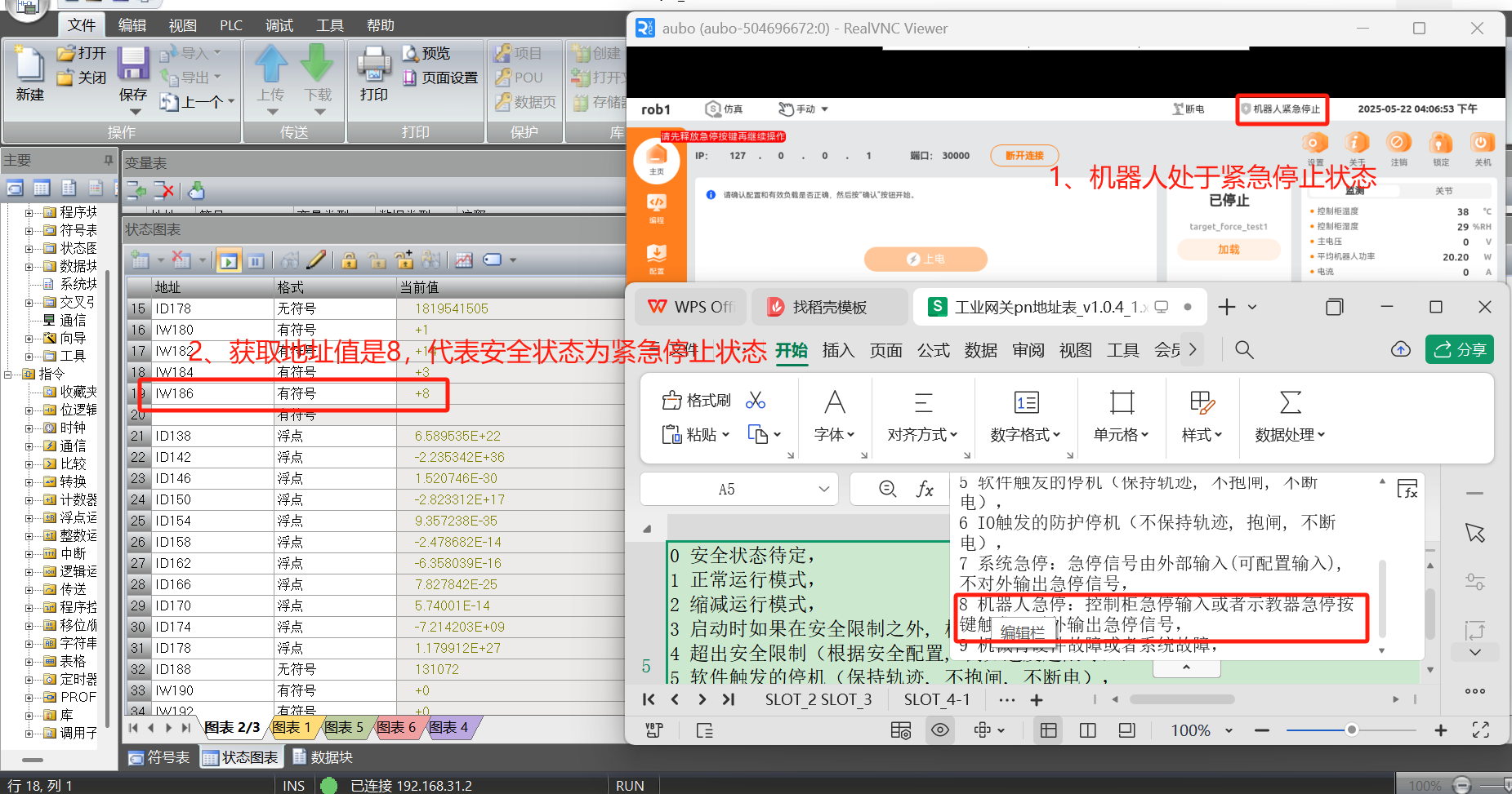
1.4.5 Reading robot status and safety status
By checking the address table and PLC start address, it is known that the IP address 184 of slot 2, with two bytes, is for accessing the robot status, and the IP address 186 of slot 2 is for accessing the safety status.
Example:
Query the current power-off status and emergency stop status of the robot arm via IP address.
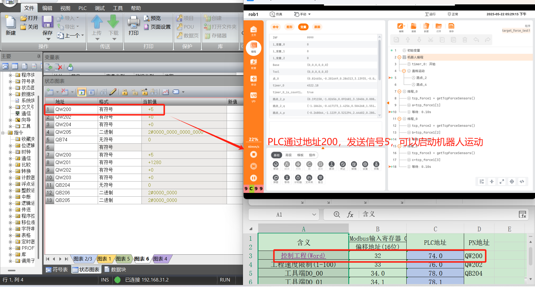
1.4.6 PLC control of robot
By checking the address table and PLC start address, it is known that the IP address 200 of slot 6, with two bytes, is defined as control engineering for controlling the start/pause/resume/stop, power-on and other actions of the robot through PLC.
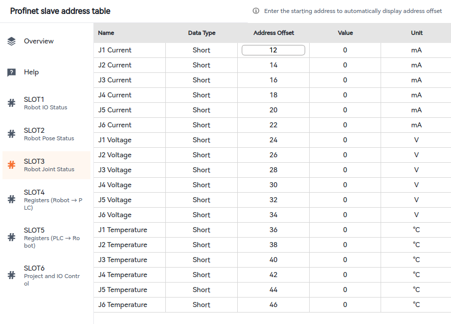
1.5 Profinet address table
1.5.1 How to display address table
The Profinet address table is displayed by default, as shown in the figure below. Click "View Address Table" to view the details of the address table.
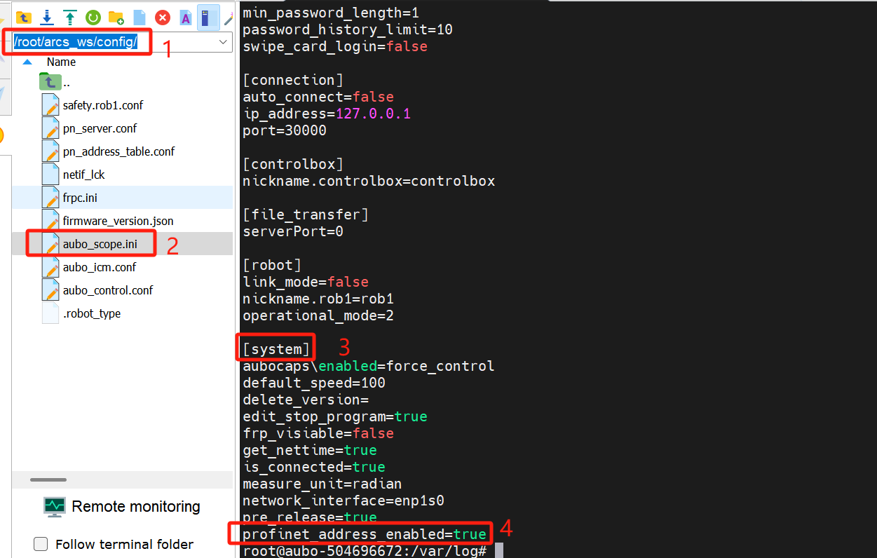
If the address table is not displayed in Configuration - Fieldbus - Profinet, modify the configuration file /root/arcs_ws/config/aubo_scope.ini and configure the field profinet_address_enabled=true under system, save the configuration and restart the ARCS, and then, the address table will be displayed.
1.6 Common problems and solutions
Some reasons and solutions for unsuccessful connection are listed below:
Confusion between robot IP address and Profinet slave IP address
Note: The IP address set on the teach pendant interface shall not be the same as that configured for Profinet by TIA Portal, otherwise connection failure or external network connection failure may occur. If this occurs, it is recommended to modify the IP address displayed on the teach pendant to another field in the same network segment.Inconsistency of configured slave name with actual name
It is required to set the salve name in TIA Portal to be consistent with the configured name, and ensure that there is no other slaves with the same name in the same LAN.Profinet plug-in upgrade
When the Profinet plug-in is upgraded, the slave needs to be assigned with a new name.Configuration file modification error
(1) For ARCS of v0.28, the Profinet On/Off button in the teach pendant is unavailable. To use the Profinet plug-in, please configure "enable_after_startup" in the configuration file to 1. For ARCS of other versions, please check whether the Profinet On/Off button is set to On. (2) The network_port in the configuration file is incorrectly configured, for which, the default setting is enp1s0 with a single quote. (3) The gsd_type in the configuration file is configured incorrectly, for which, only 2 options are supported initially, i.e., the address table compatible with the industrial gateway.GSD file import failure
Check whether the GSD file used is dedicated to the Profinet plug-in (provided in the compressed package)Different controllers, with default network port to be modified
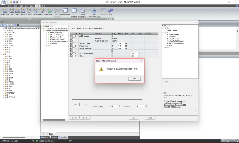
If the network port to be used is uncertain, enter "ifconfig" in the terminal in the controller to find the network port corresponding to the controllers IP address, and modify this network port into the configuration file/root/arcs_ws/config/pn_server.conf`. Turn off and then turn on the Profinet. For example, for the improved controller, it is required to modify the default enp1s0 to enp2s0, and for new C controller, it is required to modify according to the actual network port inserted, and for iS controller, no modification is required.Analysis of abnormalities in STEP-7 Micro/WIN SMART software when PLC (s7-200 smart plc) is connected to Profinet slave
When the following window pops up, it indicates that the RAM of PLC is not large enough. As shown in the figure below, the maximum allowed data input of this PLC is 128 bytes, but the total data length of slots 1 to 4 is more than 128 bytes. Therefore, this window will pop up when slot 4 is to be loaded, causing loading failure of slot 4. To solve this problem, it is required to replace with a PLC of better performance and configuration, or delete unnecessary slots with required slots loaded only.
Display of "Disconnected" after the Profinet slave service is turned on
First check whether the network cable between PLC and robot arm is connected normally and whether it allows for normal commutation via
ping.If the communication is normal, open the terminal, enter the command:
systemctl restart pn_server, and then turn off and turn on ARCS, and then "Connected" will be displayed.