Soft EIP Configuration and Installation Process
I. Application of soft EIP in Inovance PLC
1 Environmental preparation for soft EIP configuration
1.1 Environmental preparation
Click [Download Data Packet] (https://www.inovance.com/portal/serviceSupport/download)
Install the Inovance PLC debugging softwareAutoShopAutoShop software
Version:V4.10.0.0EDS file
compatible_eip_slave_v0.0.1.edsHardware
InovanceEasy 521, robot arm body, laptop, network cable, HUB or switchSoftware version
0.29.3-rc.9and above,0.31.0-beta.1and above,0.32.0-alpha.9and aboveView the corresponding port and network card
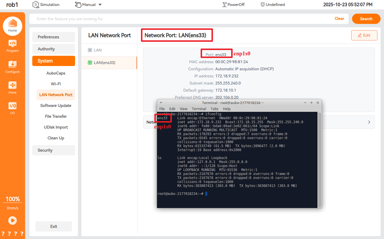
Enable the EIP service
The teach pendant software added the [EtherNet/IP] configuration function to the configuration module starting from v0.31.1. Click "Configuration > Fieldbus > EtherNet/IP" to configure the EIP service. For operations such as enabling/disabling the EIP service in the software, refer to EtherNet/IP.
1.2 Hardware wiring
Connect the PLC, the controller and the local computer to the same network through the switch;
1.3 Setting of PLC static IP address
Double-click to open the
AutoShoopsoftware, enter the main page, select [File] > [New Program], as shown in the following figure, operate according to the steps, fill in the program name, and select the Inovance PLC model Easy521;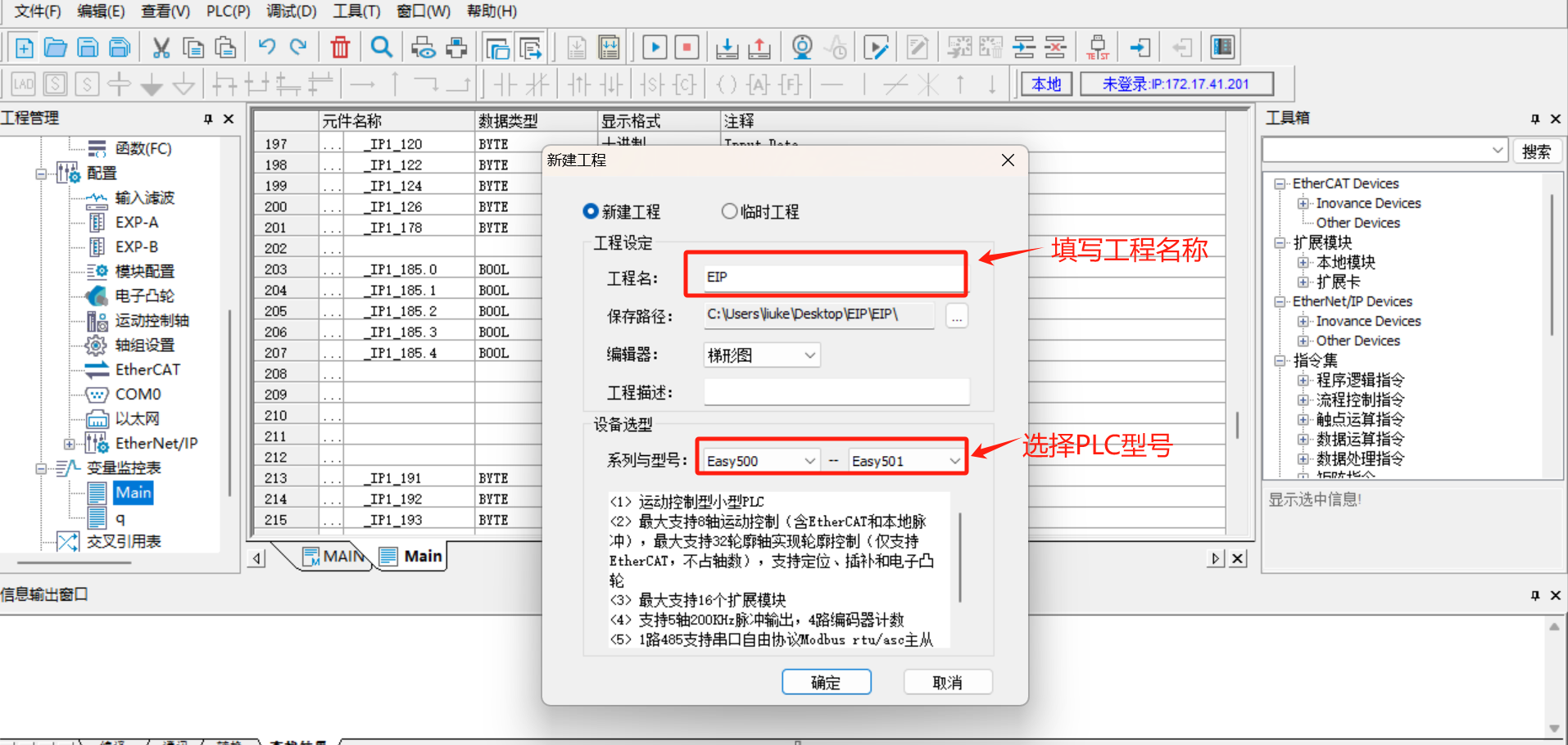
Click
Toolsin the menu bar, selectCommunication Settings, select the corresponding network port in theCommunication Typedrop-down box, and click to search PLC. After normal connection, the communicated PLC can be searched;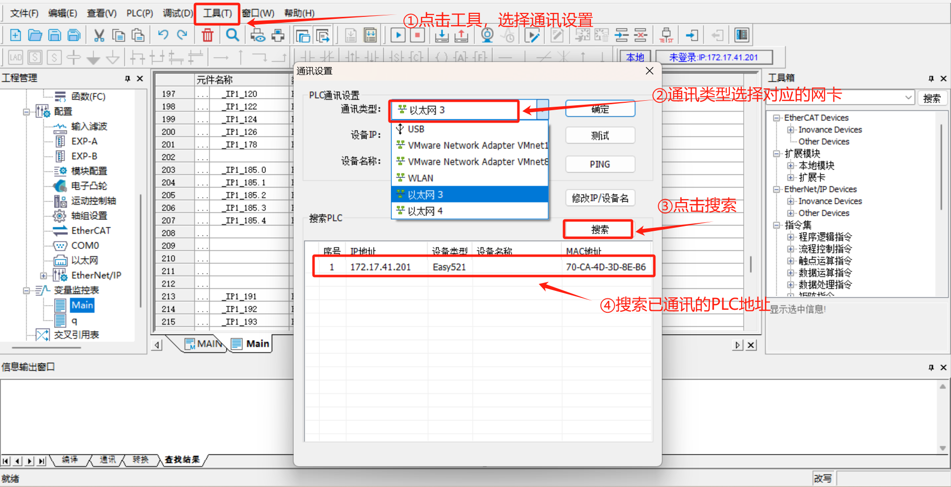
Click
Change IP/Device Nameto set a new IP address. This address must be in the same network segment as robot arm and laptop.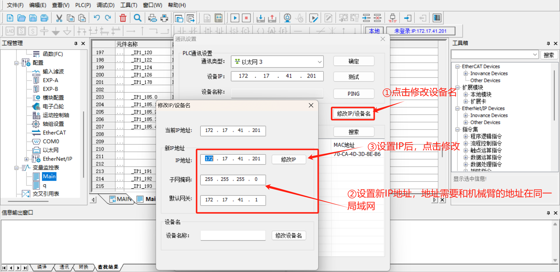
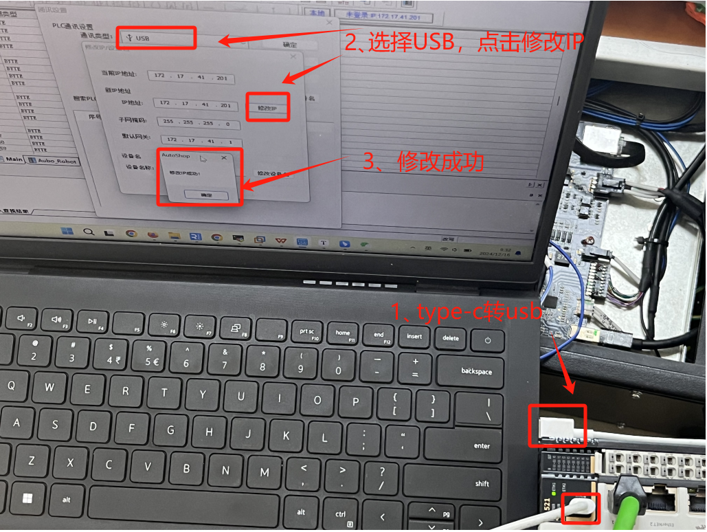
Note: If the PLC cannot be searched online, use a
type-CUSB cable to connect the PLC to the laptop, selectUSBas the communication type, and then modify the IP of the PLC;
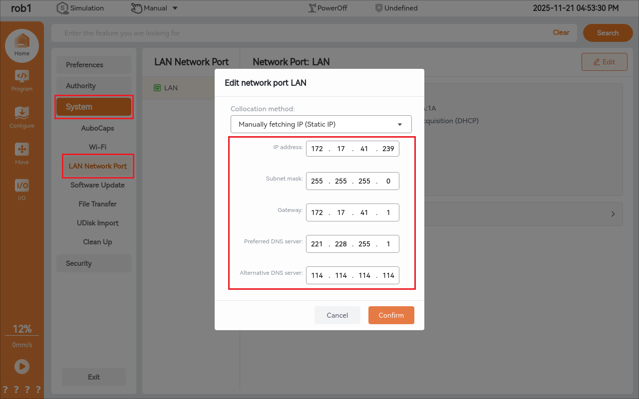
1.4 Setting of robot arm static IP
Open the arcs software and set the static IP. The static IP address must be in the same network segment as the PLC and laptop;
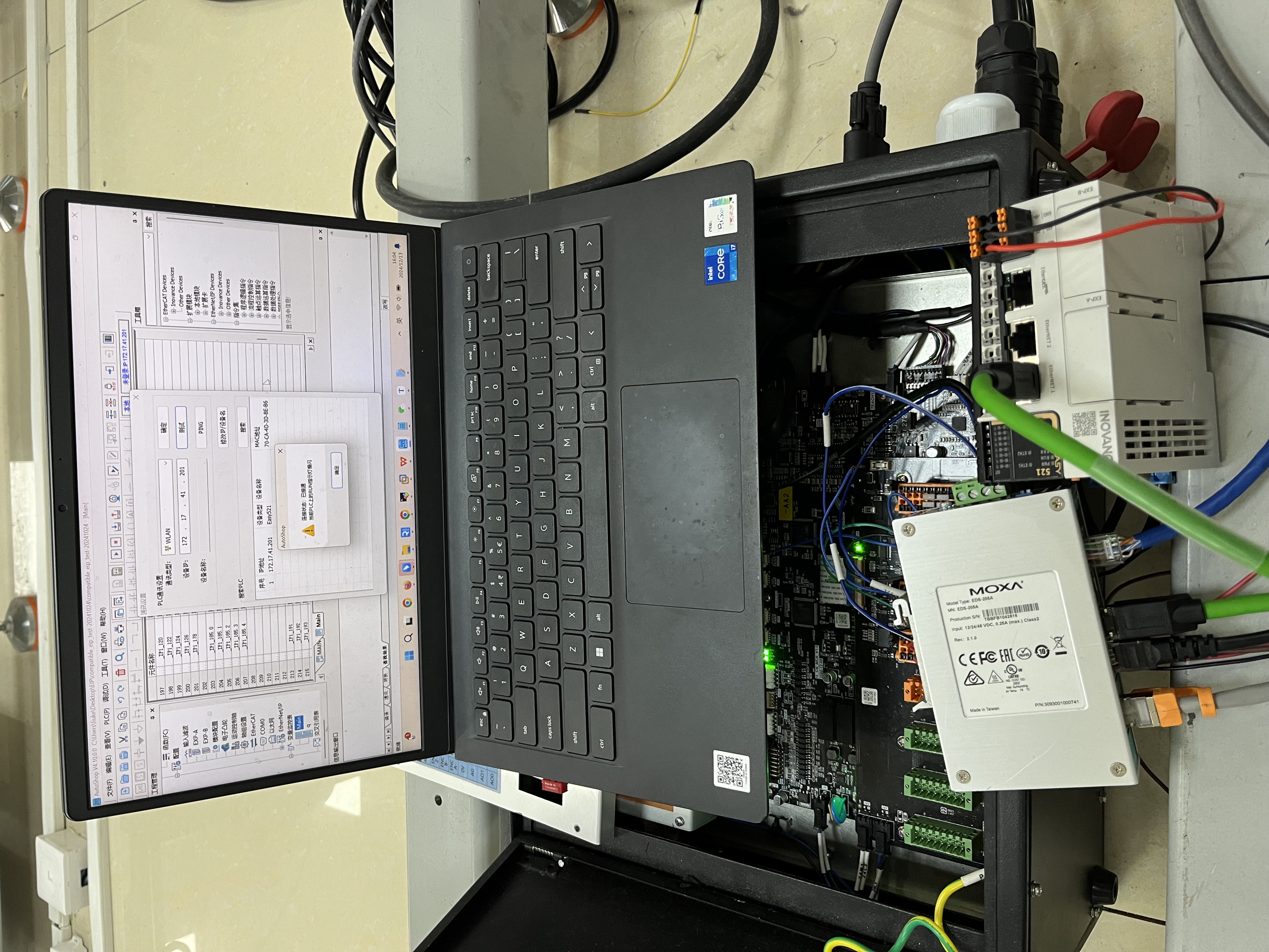
1.5 Communication test
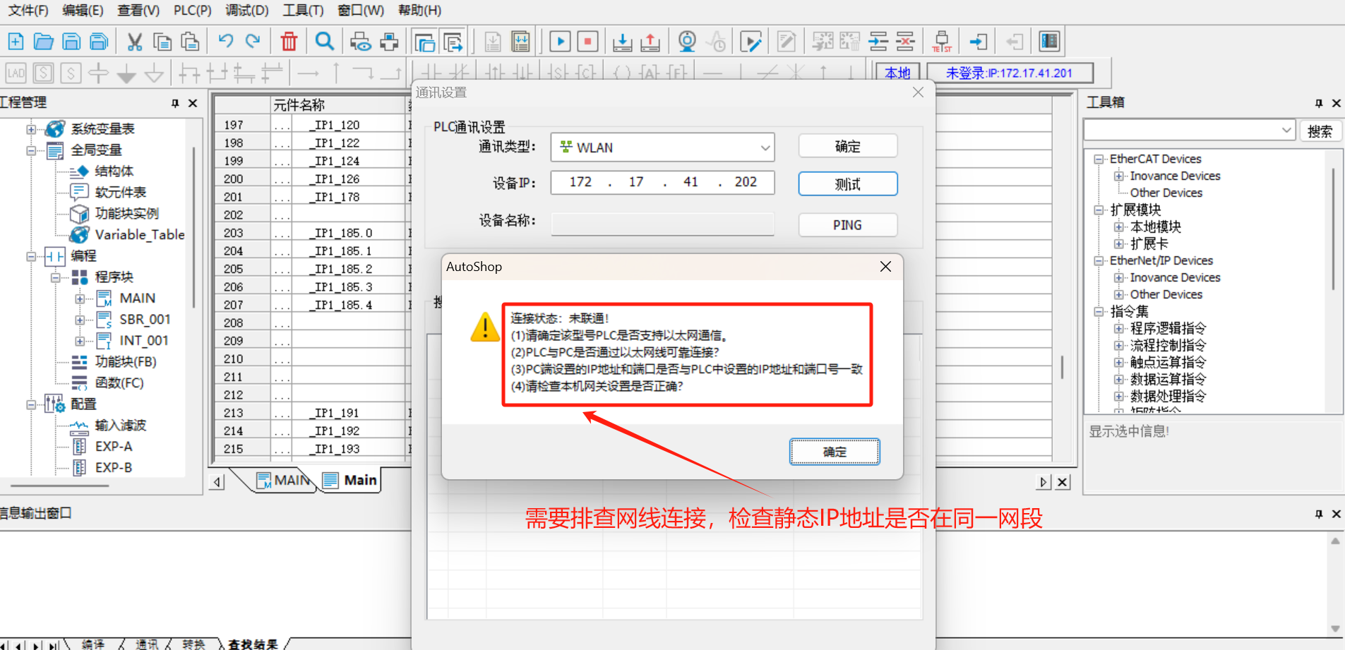
- Click
Test, if the connection is in connected status, it indicates that the PLC and laptop have established normal communication;

- If the connection is not in connected status after test, check the network cable connection and whether the set PLC IP is in the same network segment as the laptop;
1.6 PLC EDS file import
Click [Program Management] > [Configuration] > [Ethernet/IP] on the left side of the software.
Click [Toolbox] > [Ethernet/IP Device] in the menu bar on the right side of the software, right-click [Ethernet/IP Device], and [Import EDS] will appear. Click [Import EDS] to import the prepared EDS file; as shown in the following figure:
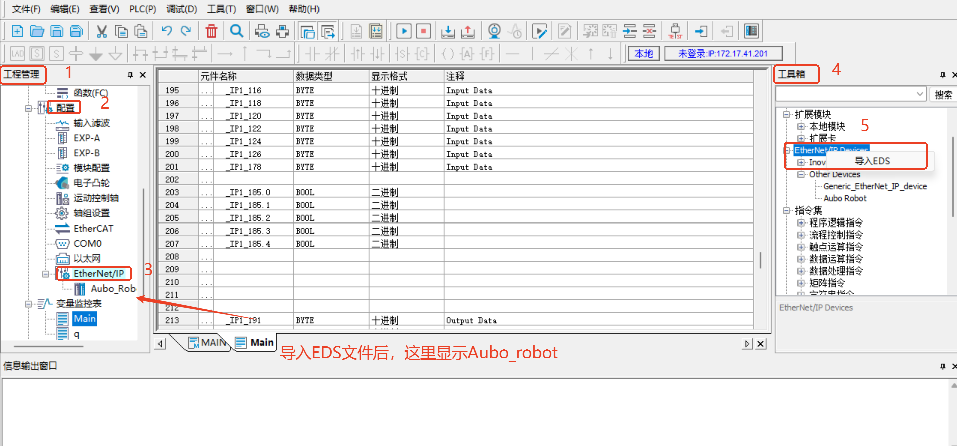
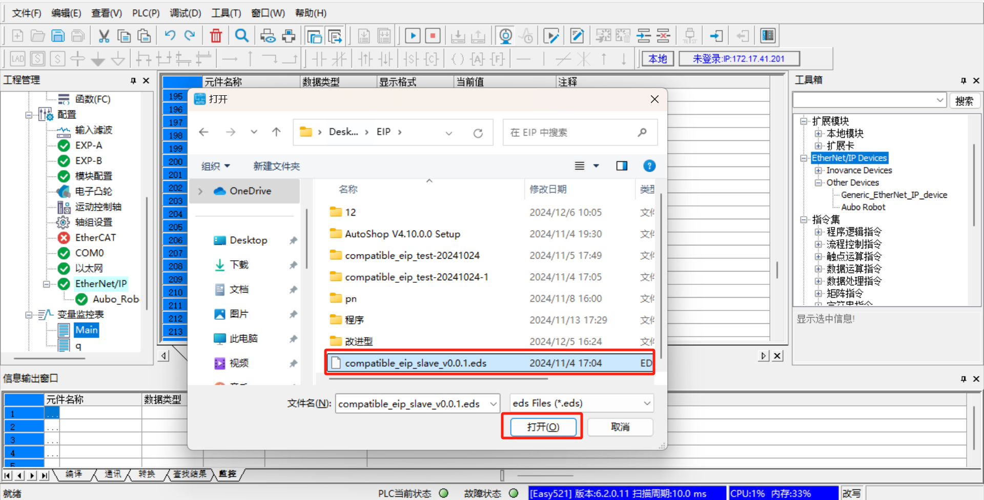
Note: The EDS file is provided by AUBO developers. Contact the relevant engineers to obtain the latest version;
1.7 Setting of device station IP
Double-click [Aubo_Robot], and set the
IP addressto the real IP of the robot arm; selectExact MatchinElectronic Match, and use the default values for others, as shown in the following figure: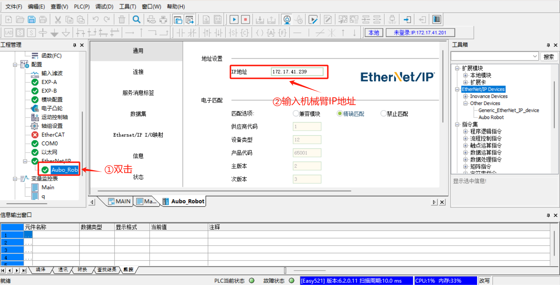
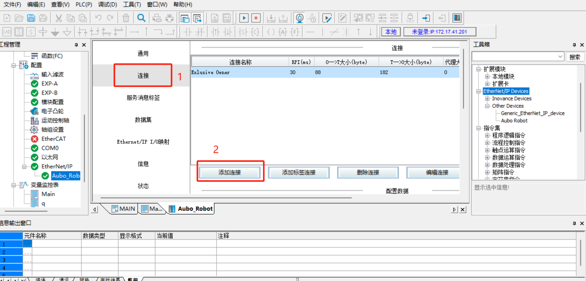
Click [Connect] > [Add Connection].
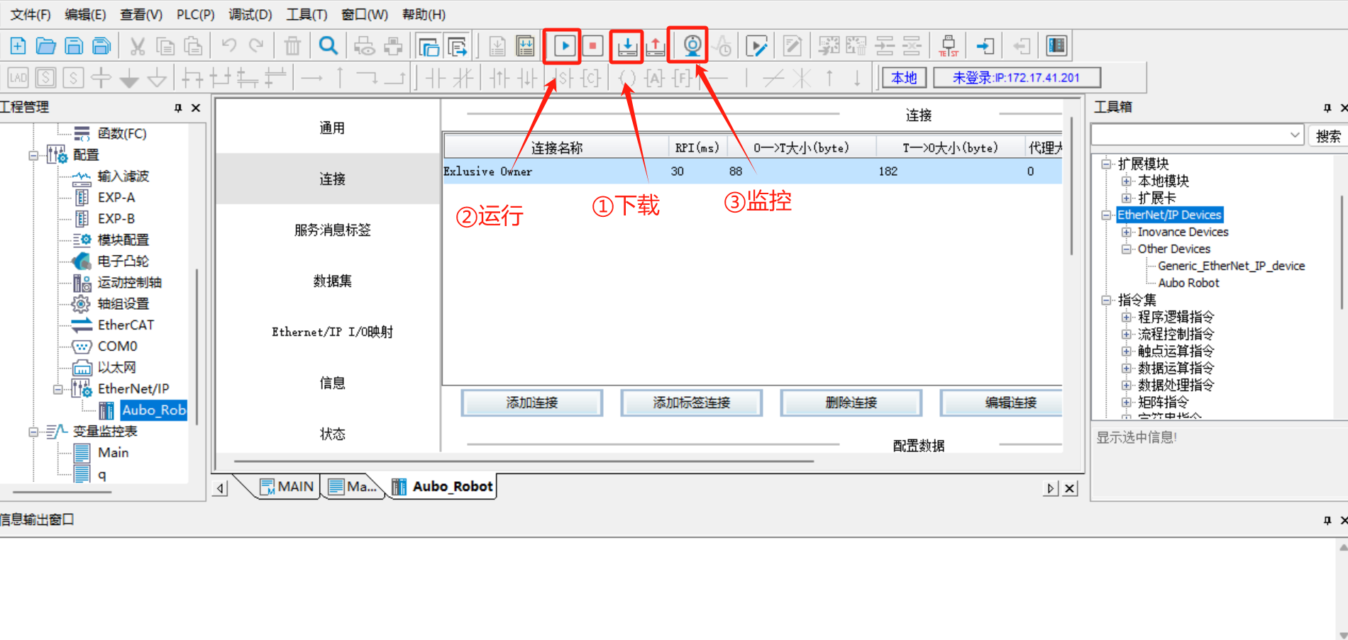
1.8 Save program > Download > Run > Monitor
After all configurations are completed, save the program, and then click [Download] > [Run] > [Monitor], as shown in the following figure:
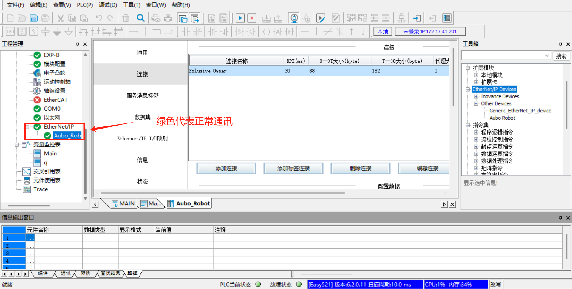
Switch the PLC to the running mode, and click [Run] > [Monitor], and then [Configure] > [Ethernet/IP] on the left. Both [Ethernet/IP] and [Aubo_Robot] turn green, indicating that the PLC is successfully connected to the robot arm and the communication is normal;
Add the monitor address variable, click [Variable Monitoring Table] > [Main] on the left, click [...] in the Main table, the dialog box [Variable Input Assistant] pops up, and then click [UserVar] > [SYS_EIP] to select the assigned address;
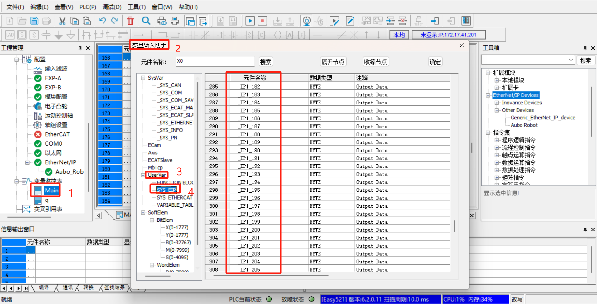
The address in
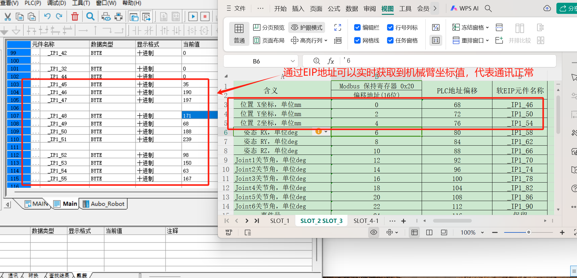
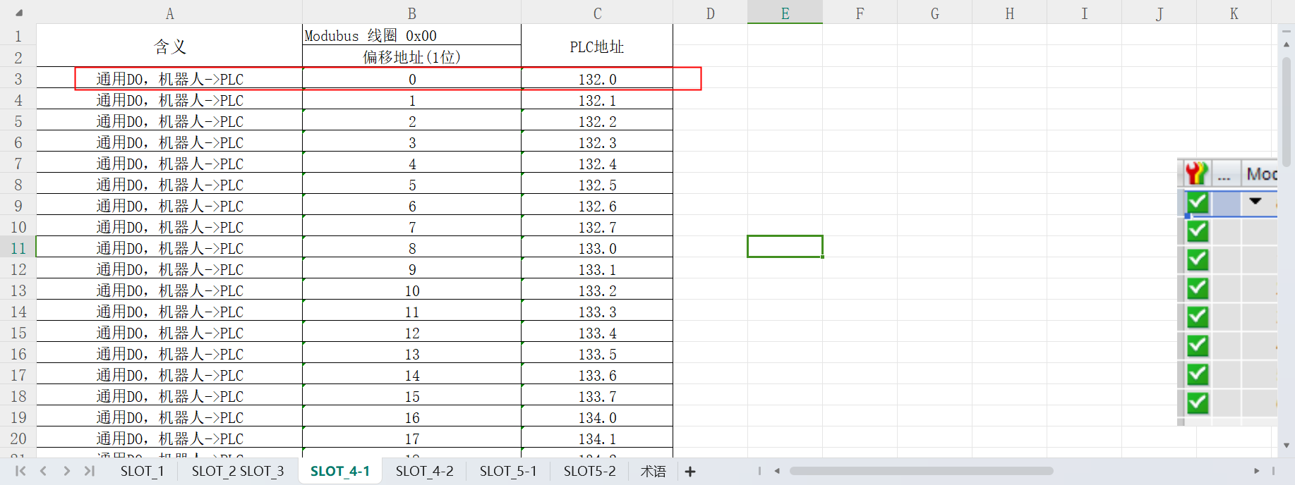
SYS_EIPis imported according to the EDS file, and is assigned by the developer according to the EIP address table in advance. The address table here corresponds to the EIP communication address table provided by the developer; the corresponding address field can be selected according to the EIP address table;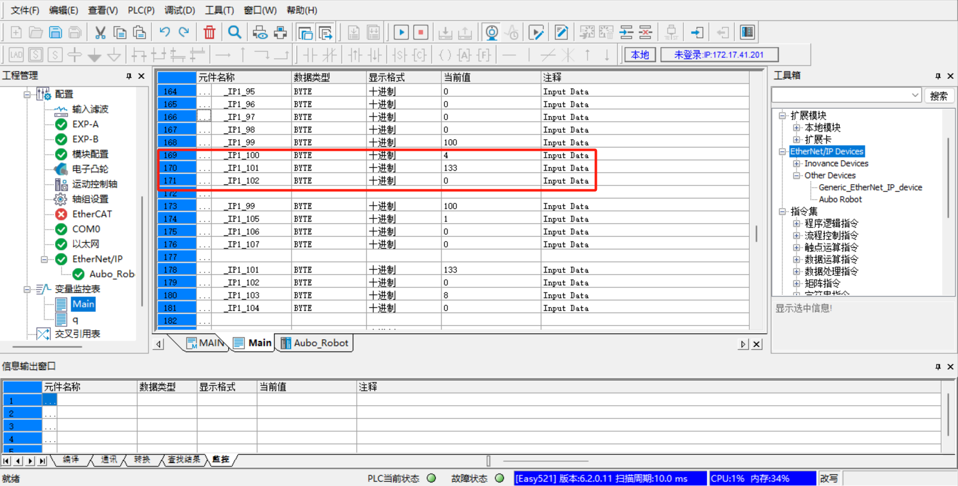
The followings are some monitor addresses added according to the EIP address table, including IO signal, position coordinates, joint angle, voltage, current, temperature, robot status, general coil (Robot => PLC), general register (Robot => PLC), general coil (PLC => Robot), general register (PLC => Robot), control program, etc;
1.9 Example of communication between PLC and controller
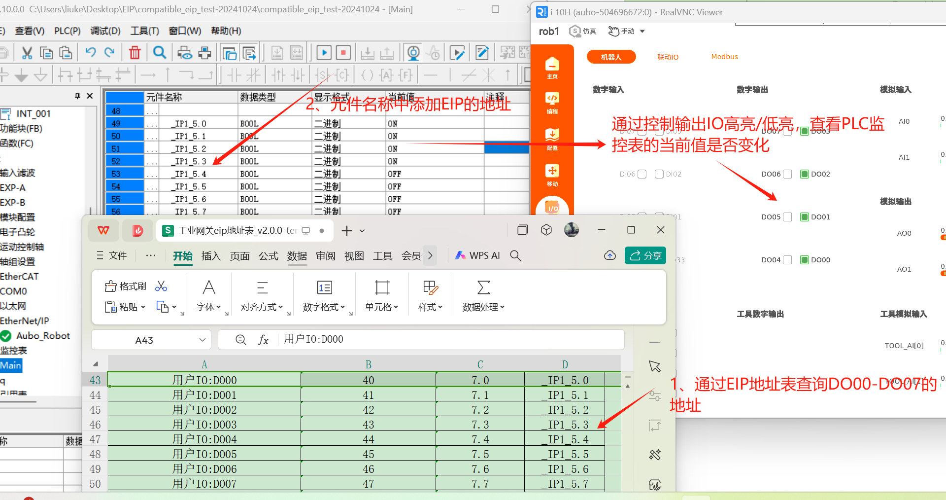
1.9.1 Slot 1 digital output monitoring
Look up the EIP address table, and the EIP addresses of DO00-DO07 are _IP1_5.0 to _IP1_5.7. Add the monitor address in the variable monitoring table, open [ARCS Software]> [IO]> [Robot]> [Digital output], make the DO01-DO07 signals highlighted, and observe whether the values in the variable monitoring table change synchronously;
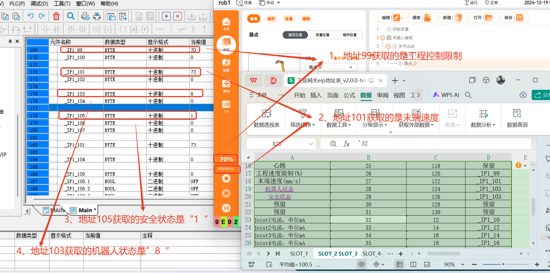
1.9.2 Slot 2 robot status monitoring
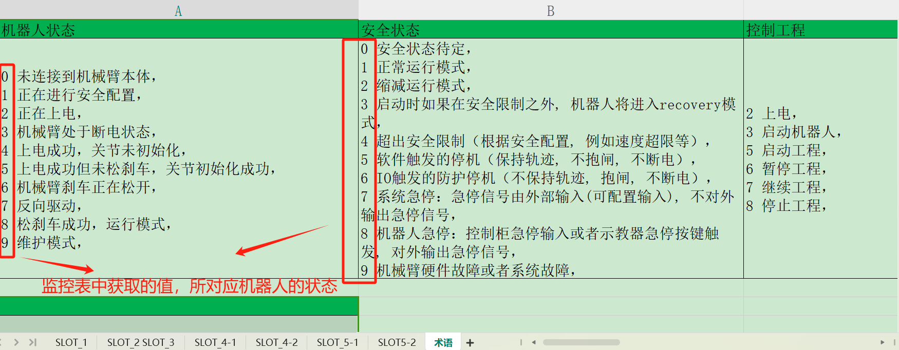
Look up the EIP address table, and the EIP addresses of program speed limit, end speed, robot status and safety status are _IP1_99, _IP1_101, _IP1_103, and _IP1_105. Add the address in the monitoring variable table, and observe the obtained value to determine the robot status.
2 Common problems
2.1 Failure to modify PLC address
- Check whether the hardware wiring is correct, whether the network cable is loose, and whether the power cable of the switch and PLC is loose;
- Connect the laptop to the PLC via the Type-C USB, and modify the IP address of the PLC;
2.2 Target device offline
- Check the network cable connection and whether the set PLC IP is in the same network segment as the laptop;
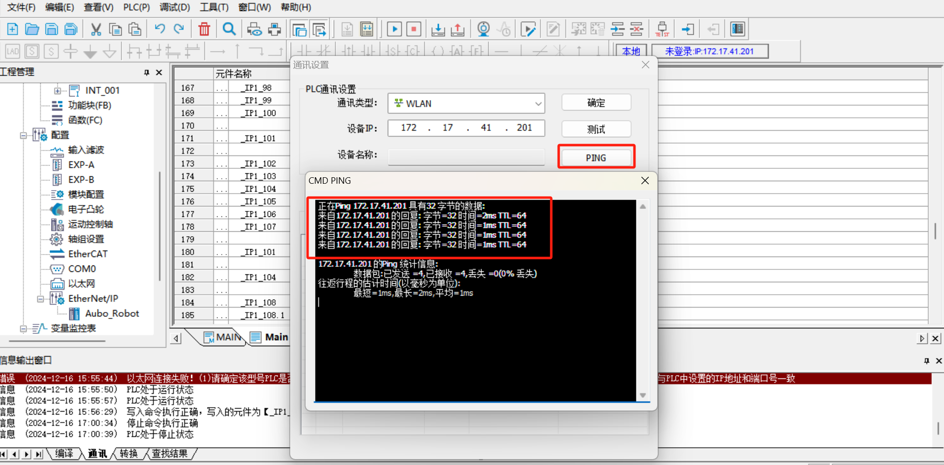
- Use the PING tool to test whether the PLC and laptop network have successful
ping. - Restart the
AutoShopand reconnect to test;
2.3 SYS_EIP address failure to be searched
- The address in
SYS_EIPis imported according to the EDS file, and is assigned by the developer according to the EIP address table in advance; - Delete [Auto_Robot] under [EtherNet/IP], delete the EDS file, and import again;
- Double-click Add [Auto_Robot] to delete the original connection and add a new connection;
- Download the PLC, click [Run] and [Monitor], and check whether the
SYS_EIPaddress can be searched; - If the problem cannot be solved in steps 2-4, restart the controller and the
AutoShopsoftware, and repeat the steps 2-4;
2.4 Successful communication but data reading error
- The data does not change, but the result is incorrect. It is necessary to check whether the address in the variable monitoring table is consistent with that in the EIP address table;
- The data changes, but the result is incorrect. If the address has two bytes, the data composed of two bytes must be sent (for example, the addresses of end speed and robot status have two bytes). If the address has four bytes, the data composed of four bytes must be read (for example, the position coordinates and joint angles have four bytes);
II. Application of soft EIP in Omron PLC
1 Environmental preparation for soft EIP configuration
1.1 Environmental preparation
Sysmac Studio software
Version:V1.52.0.64010EDS file
compatible_eip_slave_v0.0.1.edsHardware
OmronNXP1P2-9024DT, robot arm body, laptop, network cable, HUB or switchSoftware version
0.29.3-rc.9and above,0.31.0-beta.1and above,0.32.0-alpha.9and aboveView the corresponding port and network card
Enable the EIP service
The teach pendant software added the [EtherNet/IP] configuration function to the configuration module starting from v0.31.1. Click "Configuration > Fieldbus > EtherNet/IP" to configure the EIP service. For operations such as enabling/disabling the EIP service in the software, refer to EtherNet/IP.
1.2 Hardware wiring
Connect the PLC, the controller and the local computer to the same network through the switch. After the wiring is completed, use the ping command to test whether the PLC IP, the controller IP and the local IP can be connected to each other. The following operations can be carried out only after the network communication is normal;
1.3 Setting of PLC static IP address
Double-click to open the Sysmac Studio software and enter the main interface. If the PLC has been configured before and the last program is newly created and saved, directly click [Online] -> [Link to Device] option, select the connection type as
Ethernet-Hub connectionin the dialog box, set the IP address in the connection as192.168.250.1, and then click [Connect]; if the PLC has not been configured and the program is not newly created, skip this step;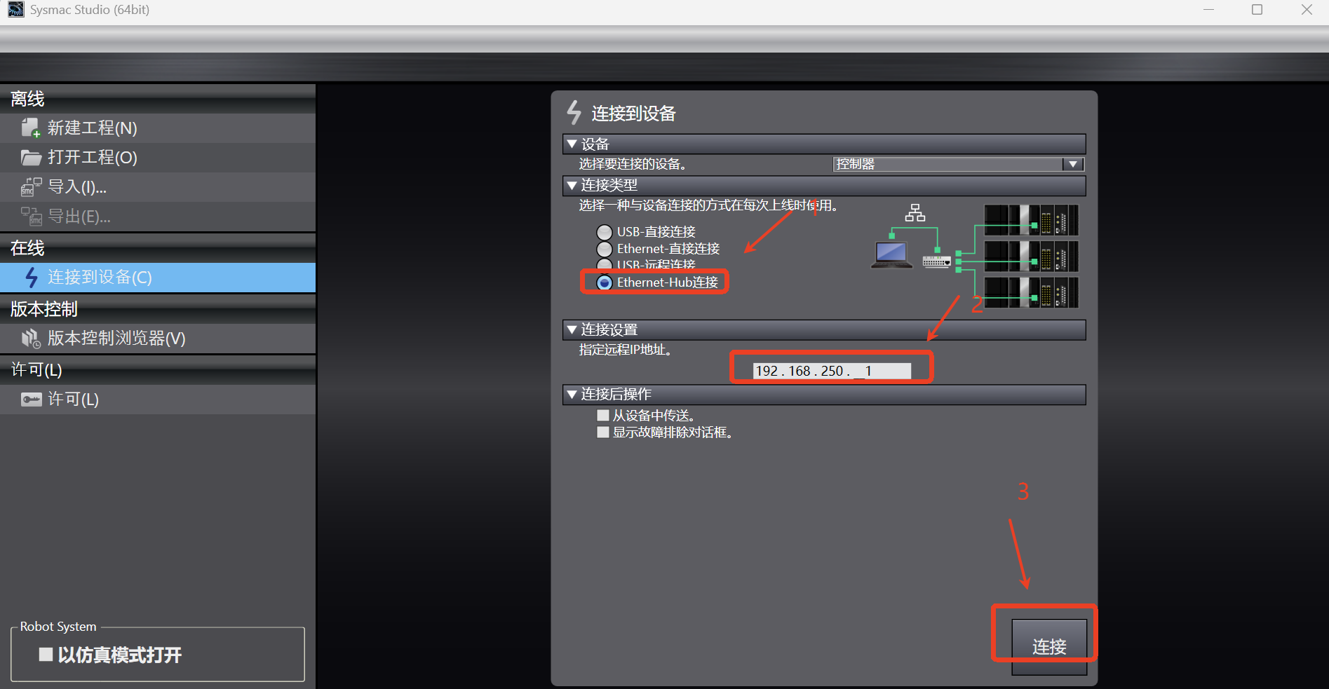
Directly click [New Program] option to pop up the dialog box, as shown in the figure below, operate according to the steps, fill in the program name, and select the Omron PLC model
NX1P2-9024DT; then click [Create] to create a new program;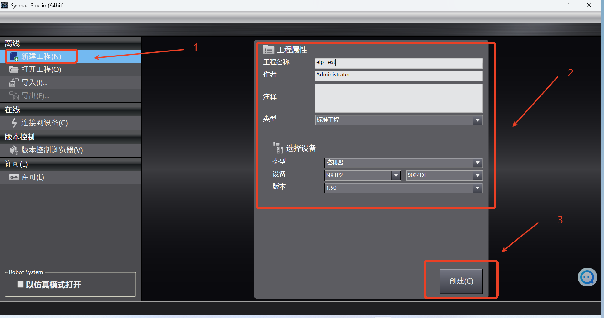
After entering the main interface of Sysmac Studio software, click [Controller] -> [Communication Settings]; the communication settings dialog box pops up. In the dialog box, according to the following steps, select the connection type as
Ethernet-Hub connection, and set the IP address in the connection as192.168.250.1. Then click [Ethernet Communication Test]. If the communication is successful, click OK to continue the following operations. If the communication fails, follow step 4 to reset the address of the PLC;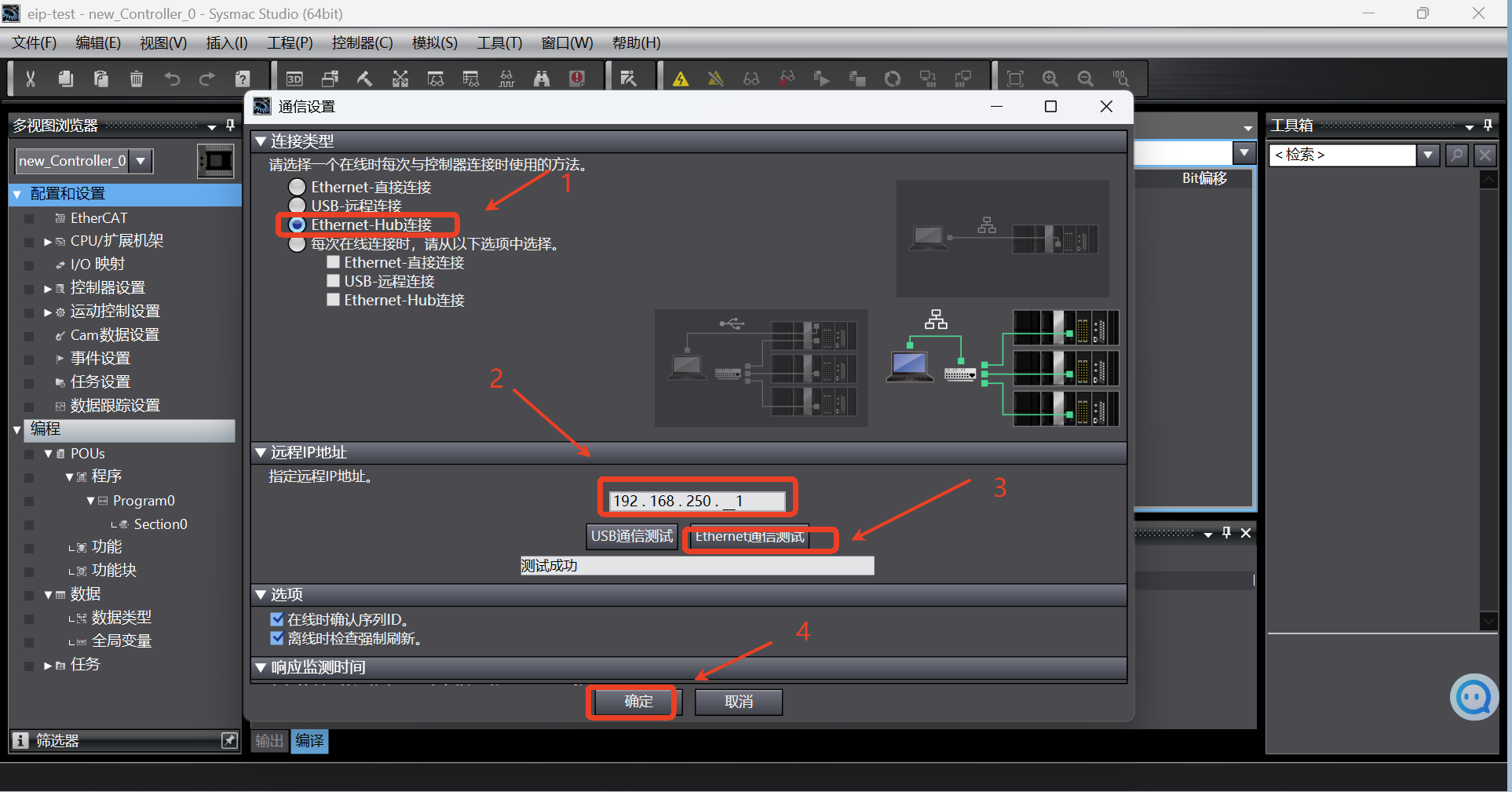
If the communication with PLC fails during the test in step 3, the IP address of PLC needs to be reset; click [Configuration and Settings] -> [Controller Settings] -> [Built-in EtherNet/IP Port Settings] in the left directory tree to enter the port setting page, select the fixed IP address in the IP address option, and fill in the IP and subnet mask; generally, the IP default address of Omron PLC is
192.168.250.1and the subnet mask is255.255.255.0, which can be used directly without change;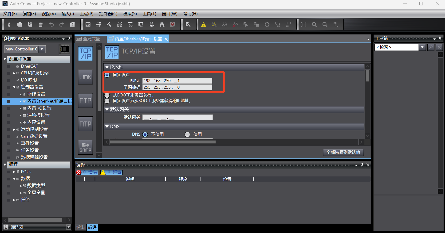
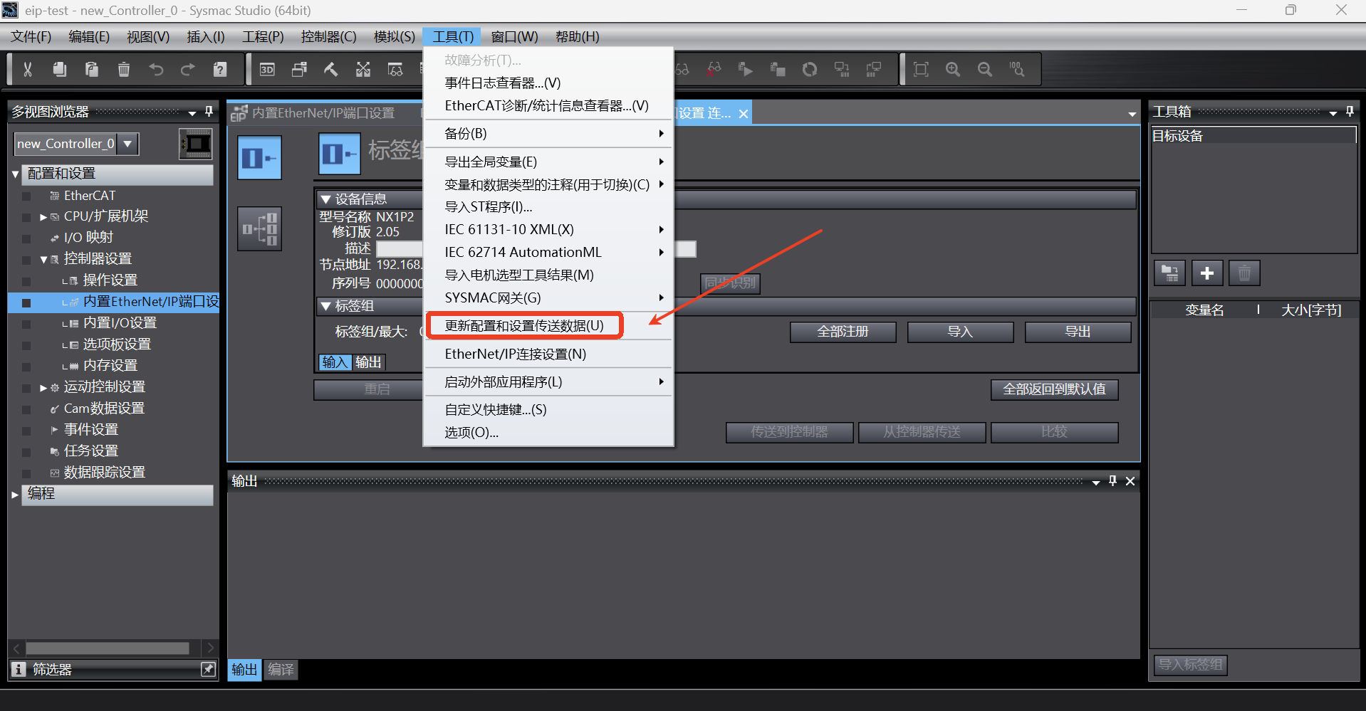
After setting, click [Tools]-> [Update Configuration and Transfer Data Settings] to update the configuration to the PLC;
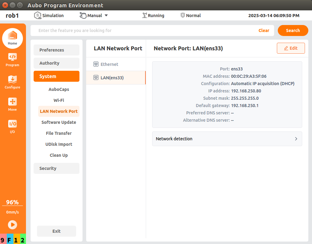
1.4 Setting of robot arm static IP
Open the arcs software and set the static IP. The static IP address must be in the same network segment as the PLC and laptop;
1.5 PLC EDS file import
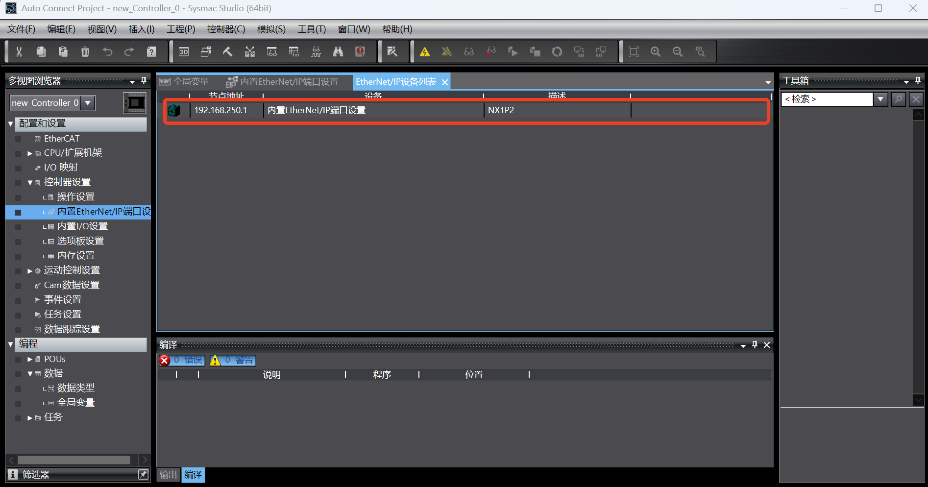
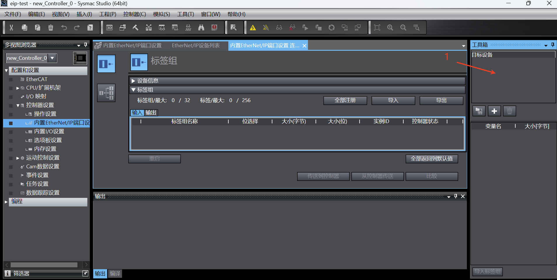
Click [Tools] -> [EtherNet/IP Connection Settings] to display the EtherNet/IP device list, and double-click the target PLC device in the device list; open [Built-in EtherNet/IP Port Settings Connection Settings] for connection configuration;
In the [Toolbox] -> [Target Device] on the right, if the eds file has not been loaded, the target device will not be displayed. Right-click with the mouse in the blank, the menu pops up, and select [Display Eds Library];
After the [Display Eds Library] is selected, the dialog box for importing eds file will pop up. Click [Install] and select the prepared eds file. Then the loaded
Aubo Robotwill be displayed in the [Vendor] list. Click [Close];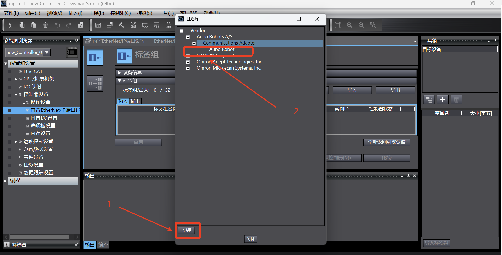
1.6 Setting of device station IP
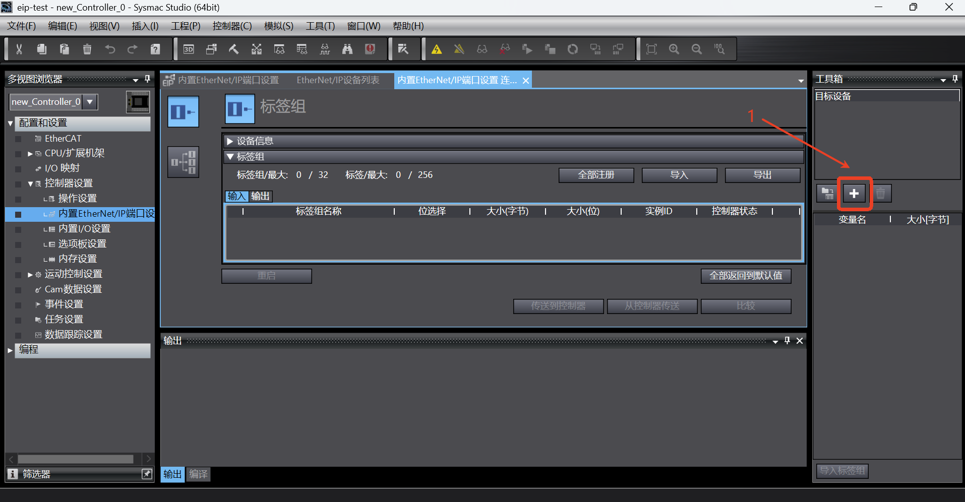
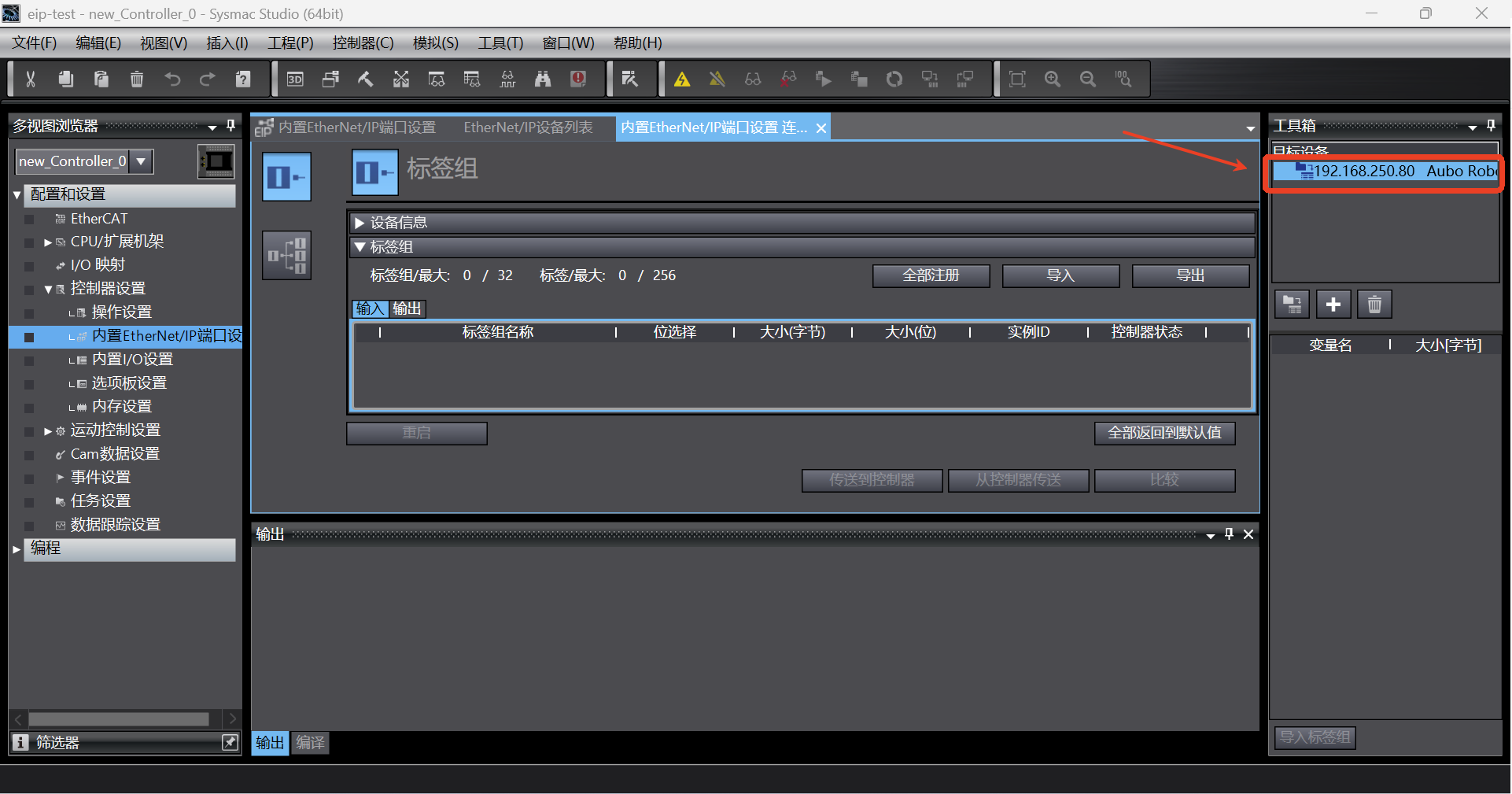
As shown in the figure below, click the Add button to add the target device;
In the toolbox displayed on the right, enter the node address (IP address of EIP service, that is, the IP address of the robot), the model name is
Aubo Robot, and the revision is 2; then click the [Add] button to add the target device;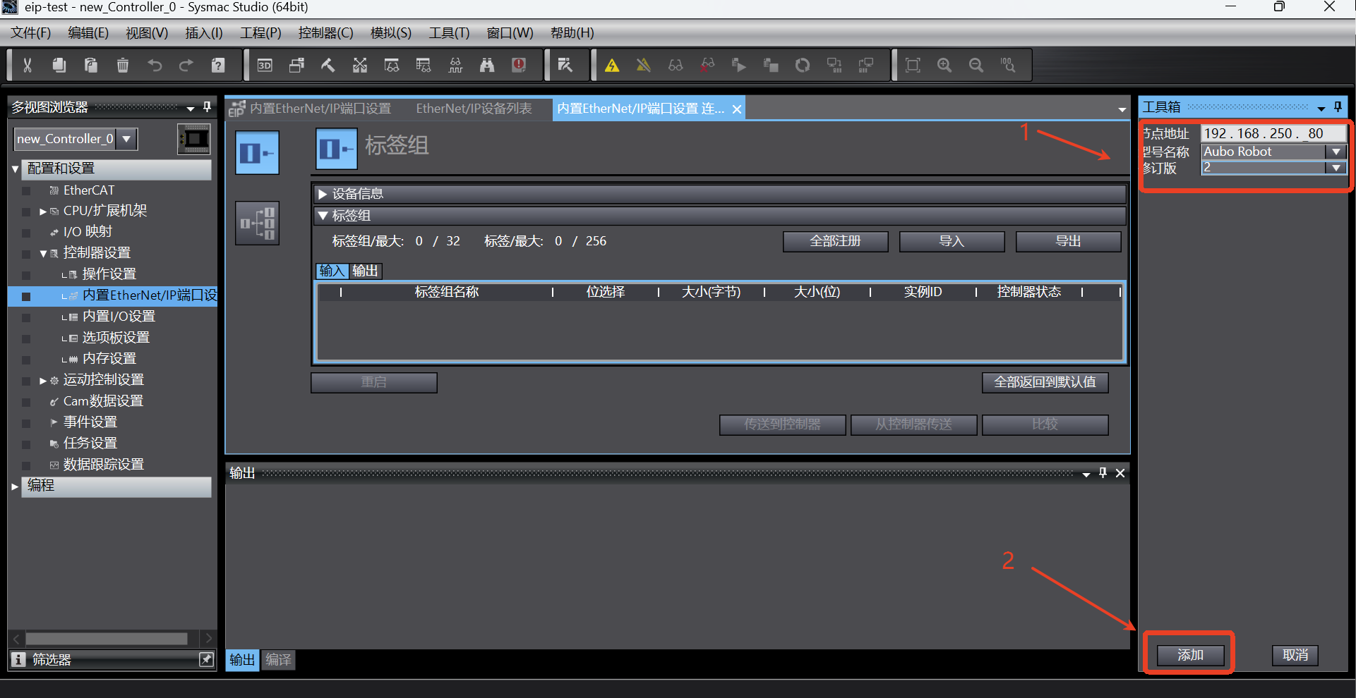
After successful addition, the target device list will display the device name, as shown in the following figure;
1.7 Setting of connection between PLC and device stack
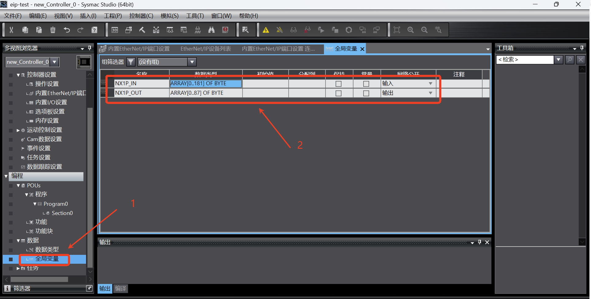
Add global variables. Click [Programming] -> [Data] -> [Global Variable] in the left directory tree to enter the global variable setting page, and add the following two input and output variables. The relevant settings of the variables are shown in the following figure;
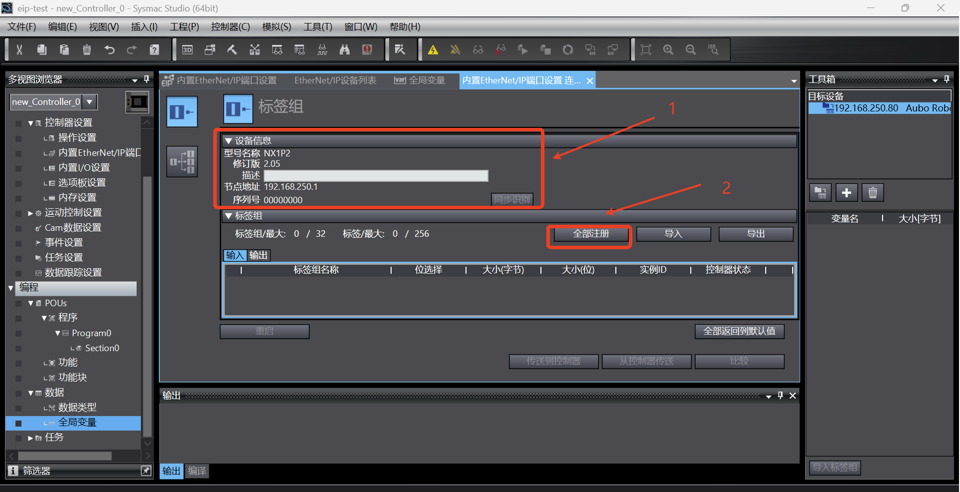
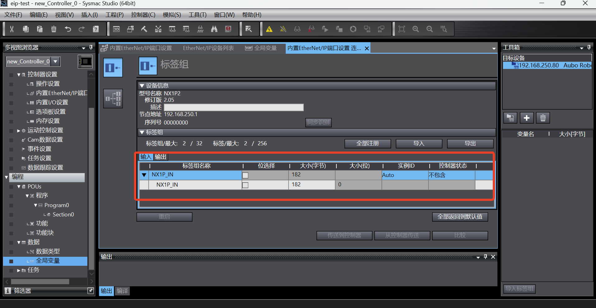
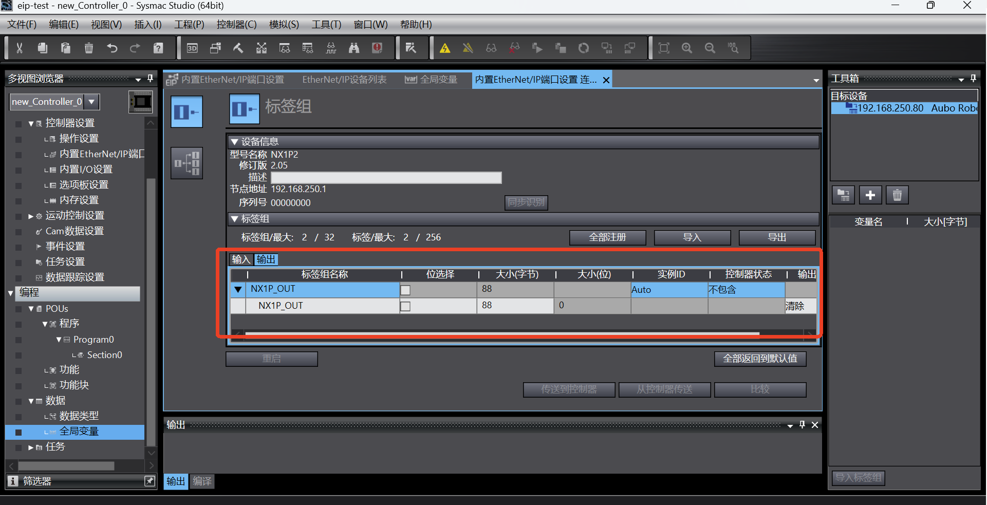
Click the tab to switch the page to [Built-in EtherNet/IP Port Settings Connection Settings]. First, check whether the device information is correct, mainly the model name and node address; then start adding tag groups. Click the [Register All] button, and the [Tag Group Registration Settings Dialog Box] pops up;
In the [Tag Group Registration Settings Dialog Box], select the input tag and output tag, and then click the [Register] button;
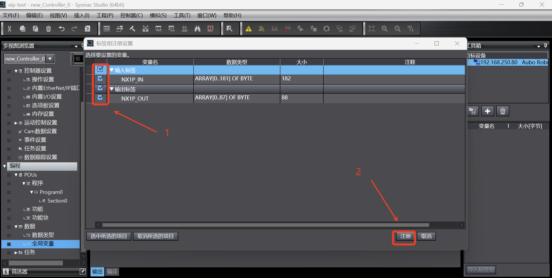
After the tag group is added successfully, the tag group is displayed as follows;
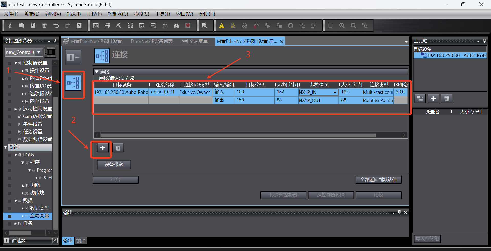
Switch to the connection tab page, click the Add button to add a connection, and then set it according to the connection parameters in the following figure. Note that the parameters here are not set at will, and must be set according to the parameters shown in the following figure;
1.8 Save program > Transfer to controller > Run > Monitor
After all the configurations are completed, save the program, click [Online] button, then click [Transfer to Controller] and the dialog box pops up. If "Yes" is selected, the connection configuration will be downloaded to the PLC, as shown in the following figure;

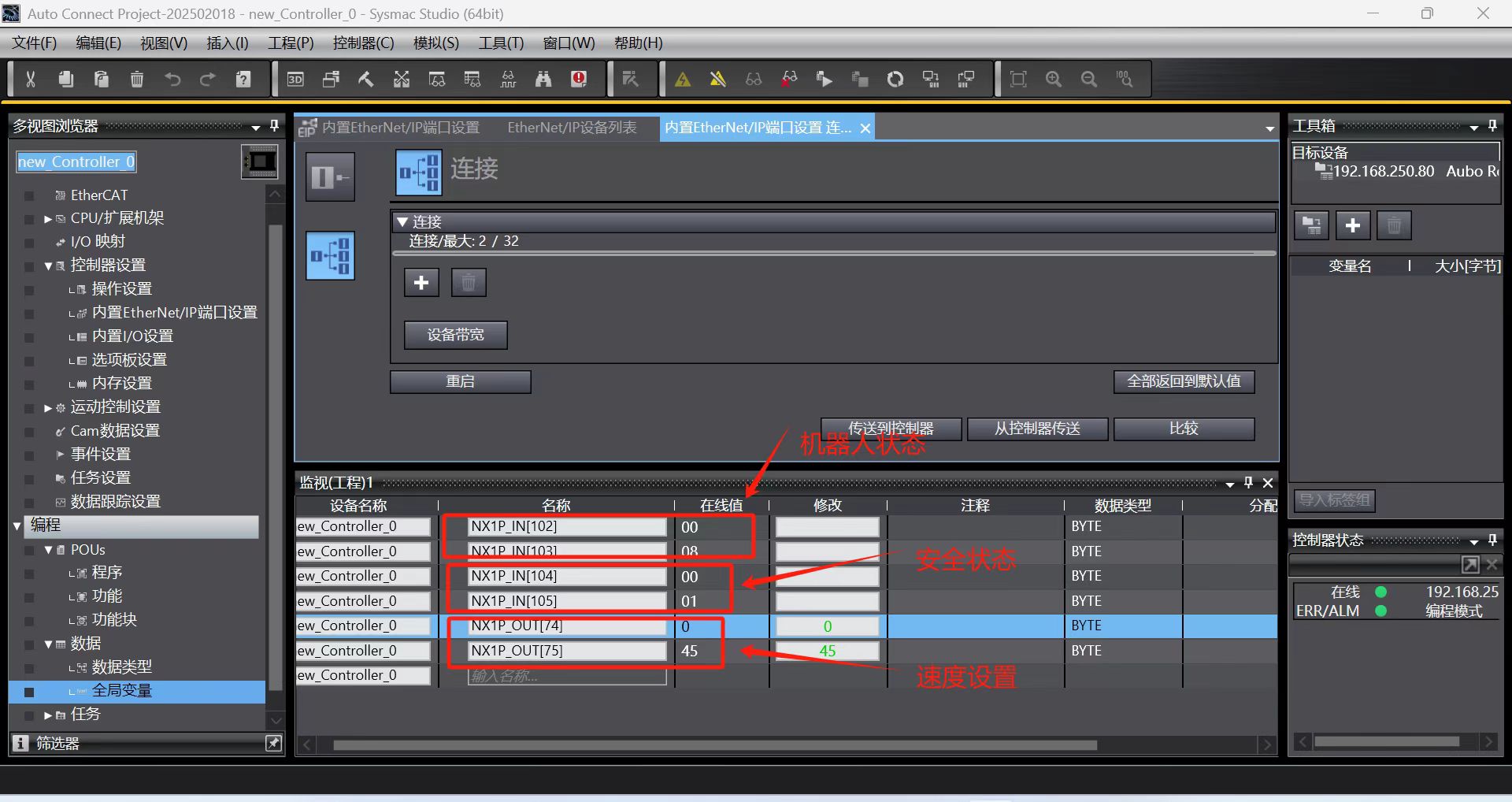
After clicking [Run]-> [Monitor], start monitoring the signal value change of the relevant address. Click [Monitor (Program)] to start adding signals. The steps are as follows;
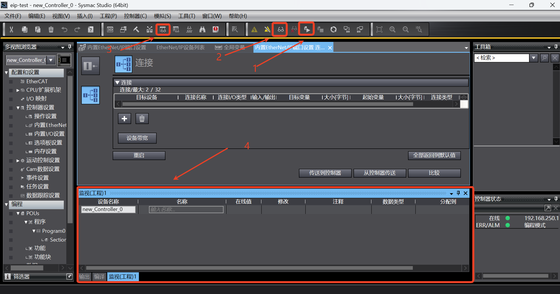
Add some example signals as shown in the figure below. If the robot status can be read and the robot speed can be set, it indicates that there is no problem with the communication of PLC ==> Robot and Robot ==> PLC:
2. Example of communication between PLC and controller
With the EIP, according to the address table, the communication between PLC and robot arm includes the followings
Robot arm IO status (slot_1)
Robot arm position and attitude (slot_2)
Robot arm joint current, voltage and temperature (slot_3)
General coil and general holding register (slot_4, slot_5)
Slot_1, slot_2, and slot_3 can be read directly through PLC, and slot_4 and slot_5 contain the content of coils and holding registers. PLC communicates with the robot arm via the ARCS script call.
This communication example only demonstrates the use of general holding register and general coil;
2.1 General coil (Robot ==> PLC)
setBoolOutput(0, true); set the first bool of PLC slot_4 start address to true.
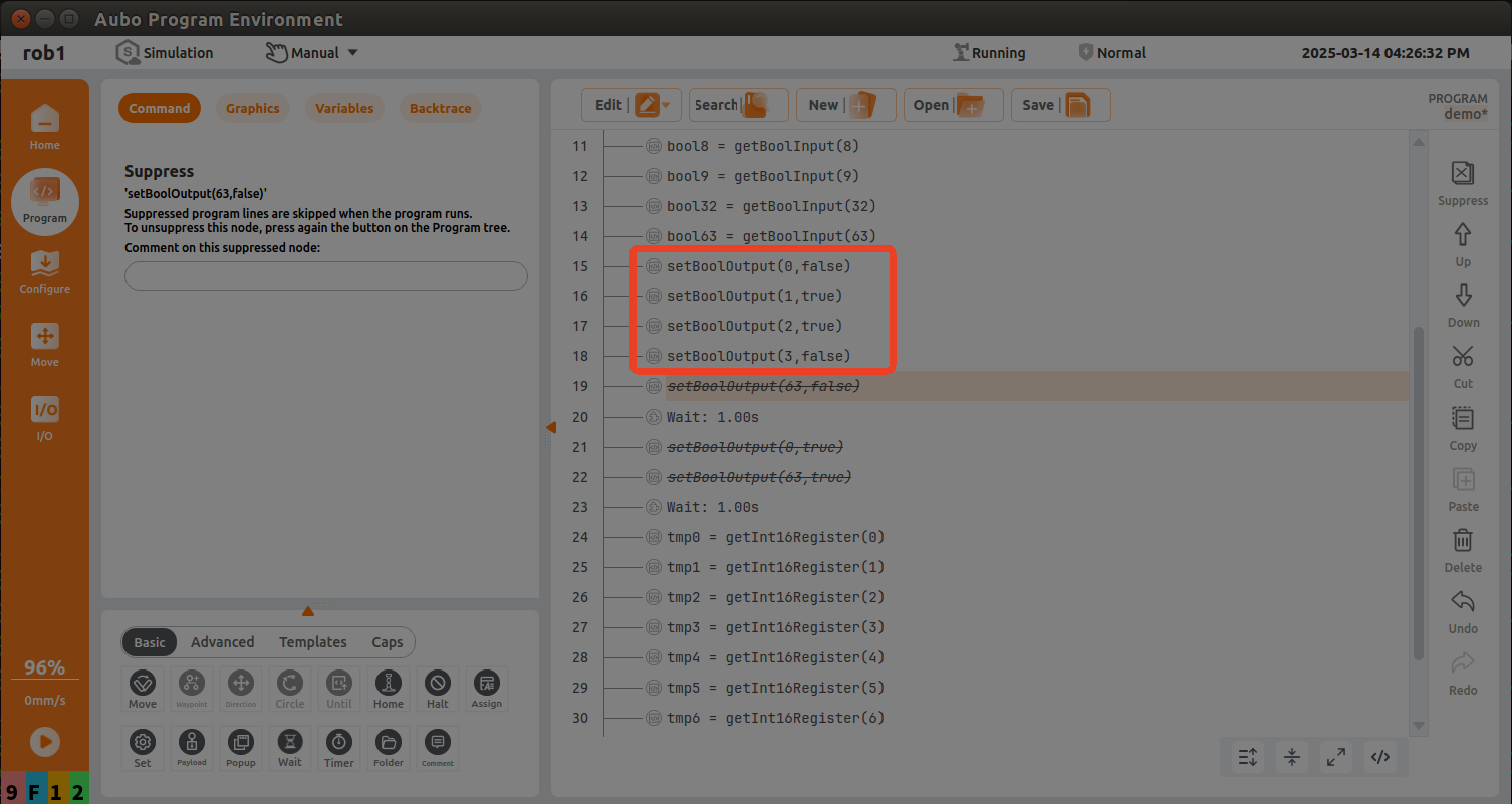
According to the address of the first general coil (Robot => PLC) in the address table, add the monitor address NX1P_IN[110] in the monitor (program) table in the Sysmac Studio software;
Add the monitor address NX1P_IN[110] in the monitor (program) table in the Sysmac Studio software; at this time, the monitor data is viewed from right to left, the 0th bit is false, the 1st bit is true, the 2nd bit is true, and the 3rd bit is false, as shown in the following figure;

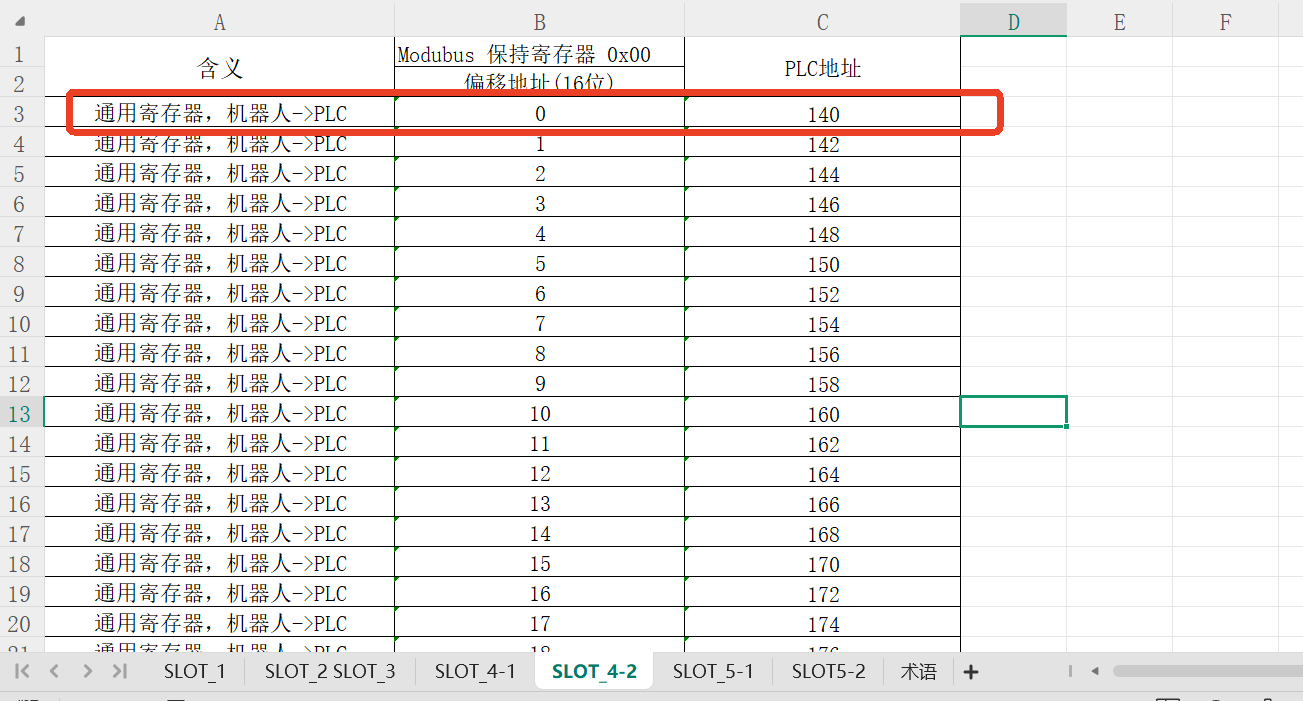
2.2 General holding register (Robot ==> PLC)
setInt16Register(32,183); write the first data of PLC slot_4 holding register (with slot_4 9th byte as holding register start address) to the value of 183, where the start address of setInt16Register is 32, and change the data to 99 after 1s.
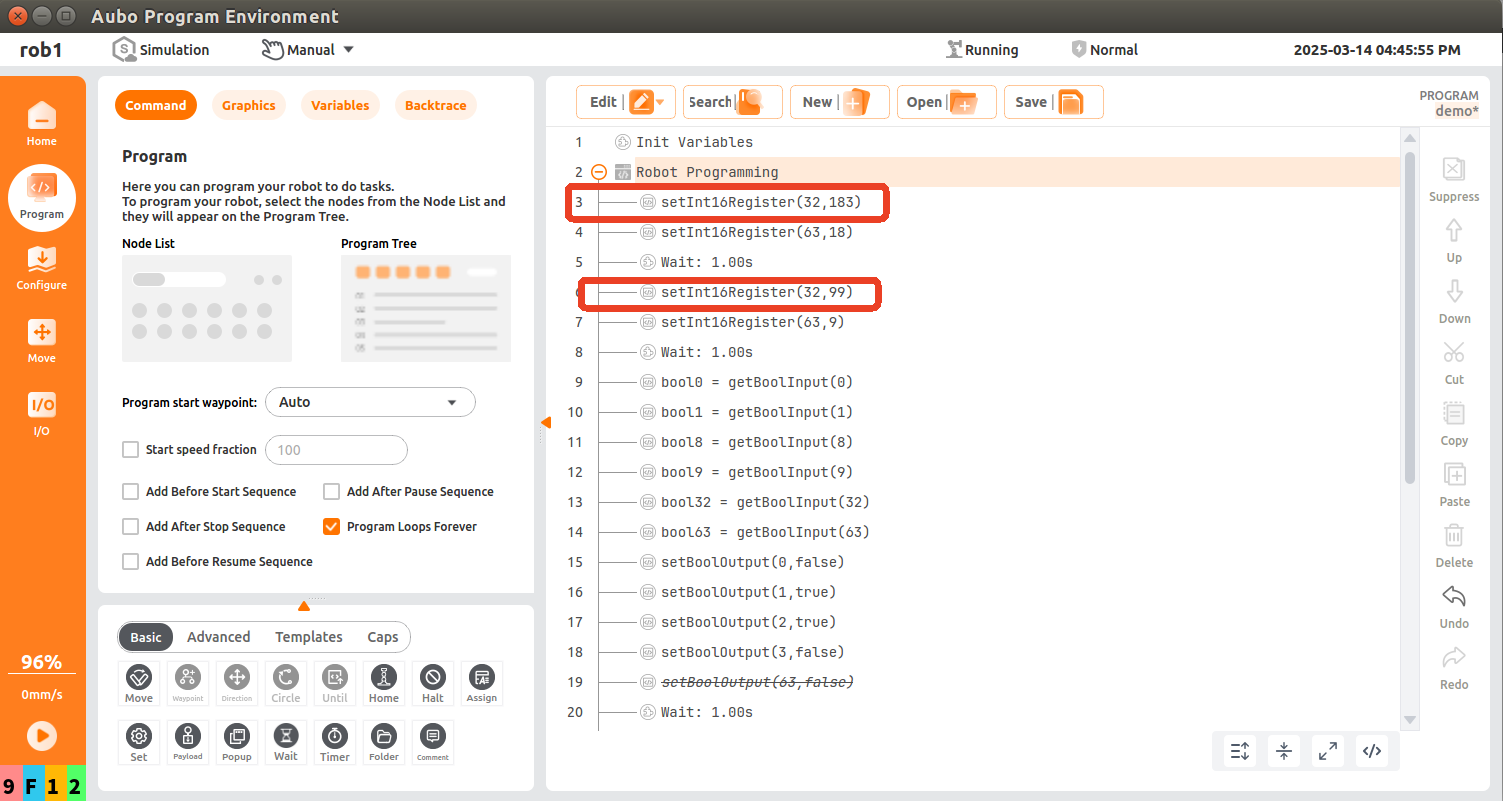
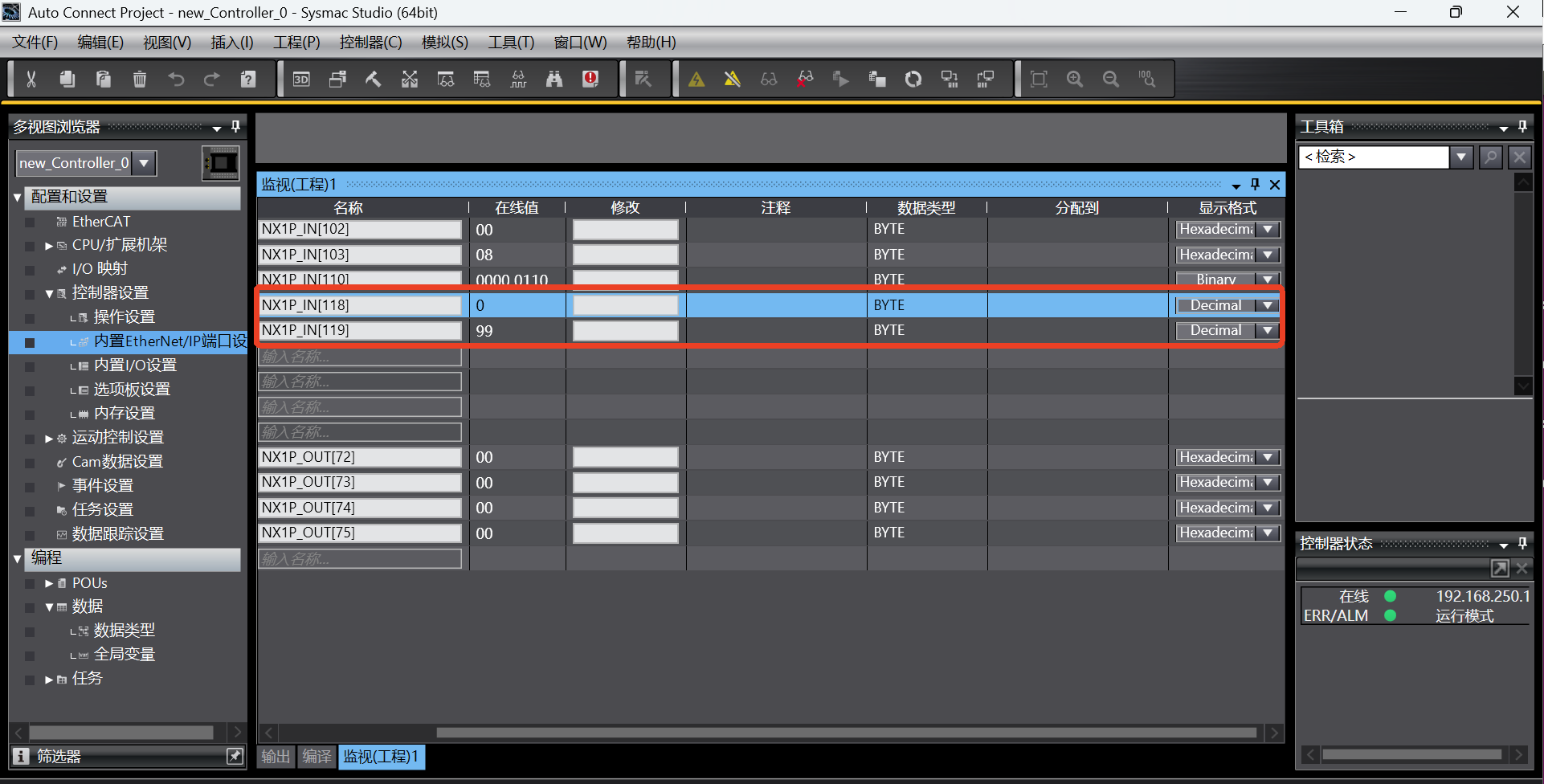
According to the address of the first general register (Robot => PLC) in the address table, add the monitor addresses NX1P_IN[118] and NX1P_IN[119] in the monitor (program) table in the Sysmac Studio software;
According to the monitor (program) table in the Sysmac Studio software, the monitor data is 183 at this time. After 1 s, the monitor data changes to 99; it can be seen that the monitor data changes between 183 and 99;
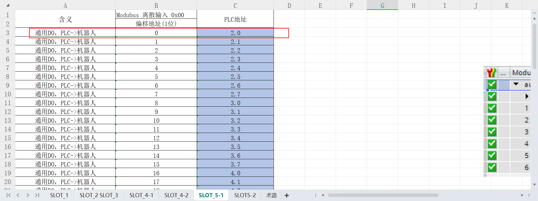
2.3 General coil (PLC==>Robot)
According to the address of the first general coil (PLC => Robot) in the address table, add the monitor address NX1P_OUT[3] in the monitor (program) table in the Sysmac Studio software;
Write 0000 0001 to the address NX1P_OUT[3] in the monitor (program) table in the Sysmac Studio software;
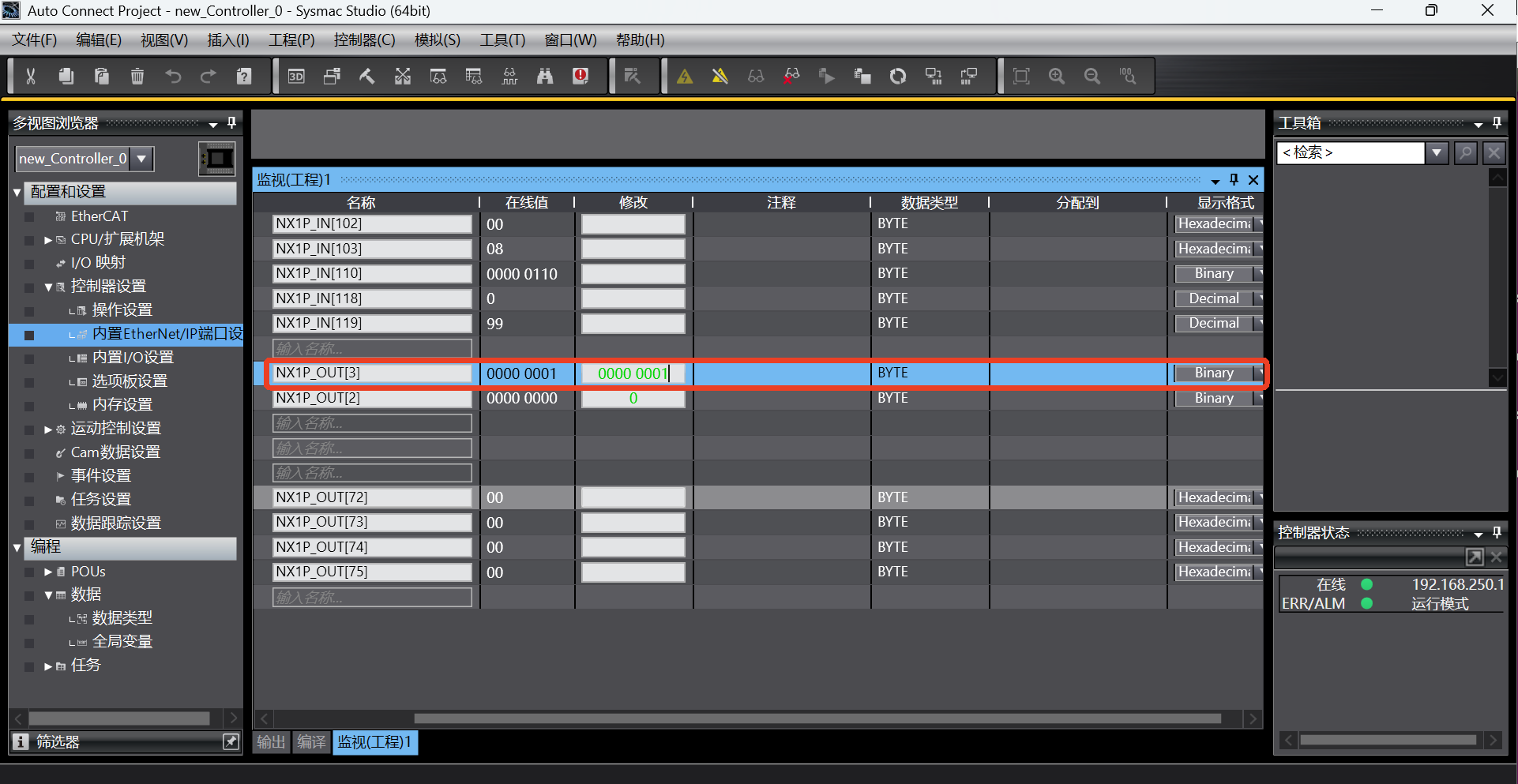
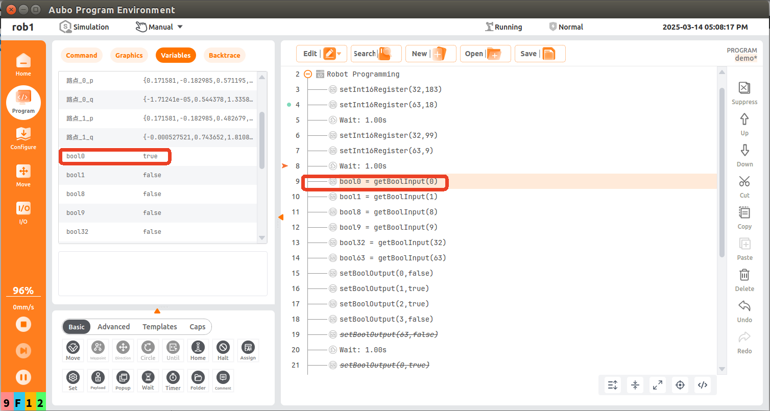
bool0 = getBoolInput(0); read the first bool of PLC slot_5 start address and save it in the variable bool0. At this time, the value of the corresponding address of PLC is read as true;
2.4 General holding register (PLC ==> Robot)
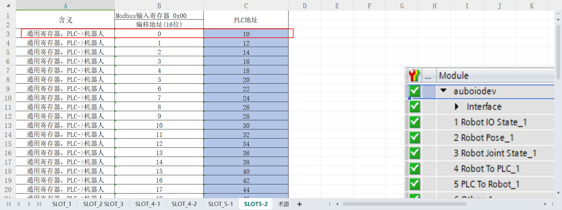
According to the address of the first general register (PLC => Robot) in the address table, add the monitor addresses NX1P_OUT[8] and NX1P_OUT[9] in the monitor (program) table in the Sysmac Studio software;
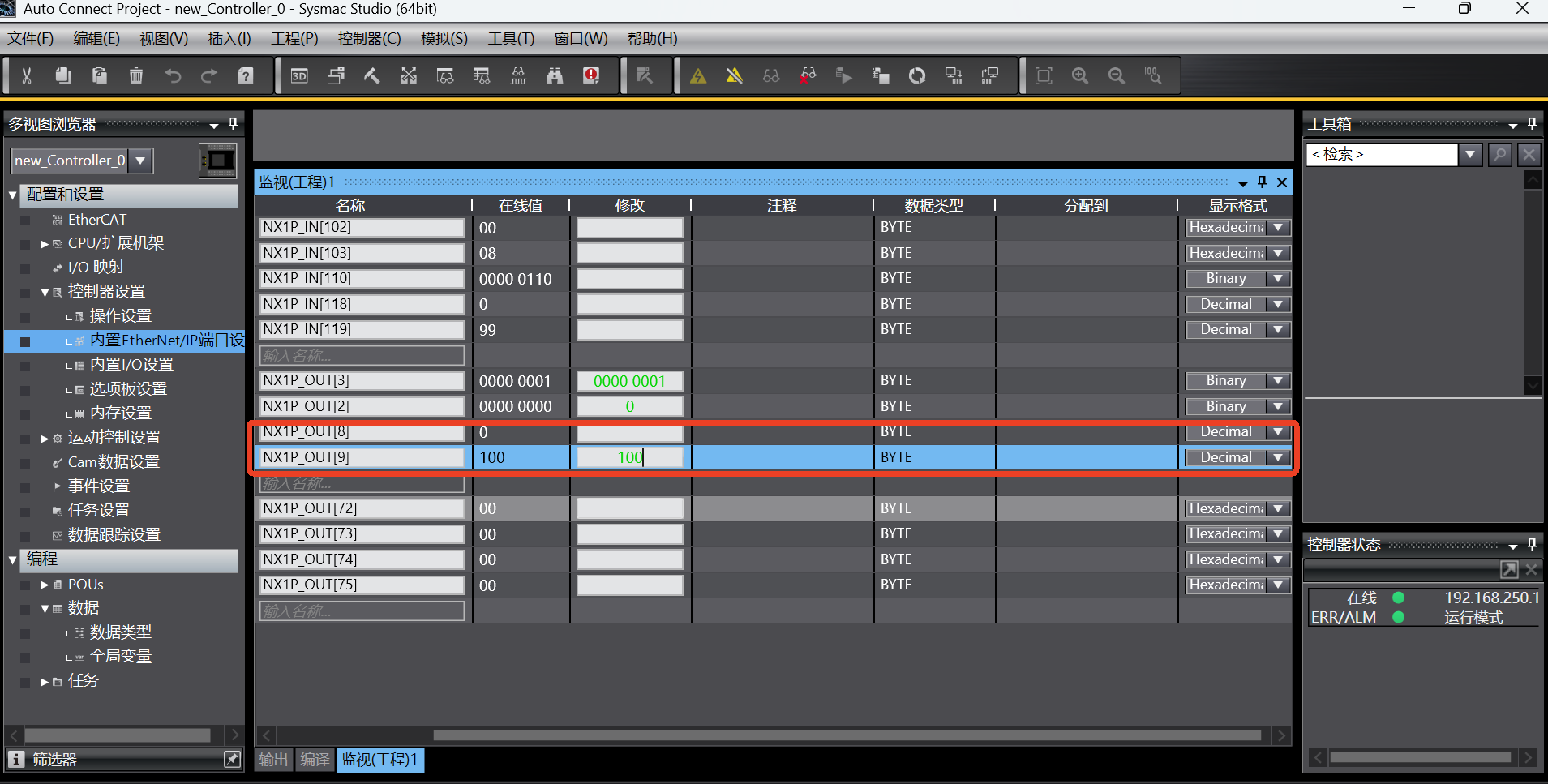
Write 100 to the addresses NX1P_OUT[8] and NX1P_OUT[9] in the monitor (program) table in the Sysmac Studio software;
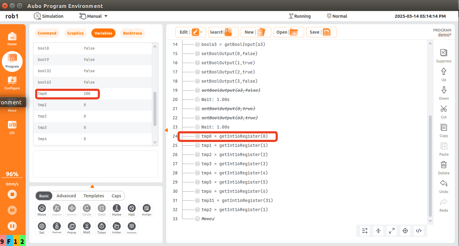
tmp0 = getInt16Register(0); the robot reads the first register (16Bit) starting from the 9th byte of PLC slot_5 and saves it in the variable tmp0. At this time, the value of the corresponding address of PLC is read as 100;
3 Common problems
3.1 Failure to modify PLC address
Check whether the communication is normal. If the communication is not normal, check whether the hardware wiring is correct, whether the network cable is loose, and whether the power cable of the switch and PLC is loose;
3.2 Successful communication but data reading error
- The data does not change, and the result is incorrect. It is necessary to check whether the address in the variable monitoring table is consistent with that in the EIP address table. The address used may be incorrect;
- The data changes, but the result is incorrect. If the address has two bytes, the data composed of two bytes must be sent (for example, the addresses of end speed and robot status have two bytes). If the address has four bytes, the data composed of four bytes must be read (for example, the position coordinates and joint angles have four bytes);