
Cycle Time Optimization
1. Purpose and Background
- Goal: Shorten the robot's cycle time and improve production efficiency by optimizing the program structure, motion transitions, and signal logic.
- Scope: AUBO collaborative robots.
2. Problem Description
- The overall program cycle time is too long (the single-cycle time exceeds expectations, limiting the production line cycle time).
3. Cause Analysis
| Category | Cause description | Typical manifestation | Optimization direction |
|---|---|---|---|
| Motion planning issues | Motion planning parameters or trajectory transitions are unreasonable | - Pauses between motion segments - Continuous motion with blend radius is not used - moveJoint/moveLine parameters are set conservatively | Increase speed/acceleration, enable blend radius, optimize posture and path |
| Logic structure issues | Program logic blocks the main flow | - Fixed delays exist (sleep, wait)- Conditional checks block serially - Structure nesting too deep, complex branches | Optimize wait logic to avoid pure fixed delays Use conditional pre-reading |
| Signal interaction issues | Too many signal waits or handshake logic | - IO signal synchronous waiting - Peripheral response time is long - No timeout exit mechanism | Add motion event triggers or independent-thread IO monitoring Add signal timeout logic |
| External system influence | Peripheral equipment cycle time and PLC logic not optimized | - Robot waits for host signals - External control pace is slow | Optimize external flow, parallel control, or signal pre-reading |
4. Optimization Approaches and Examples
4.1 Motion Transition Optimization (Three Main Methods)
At the collaborative robot application level, motion transition optimization is the key to shortening the cycle time and improving smoothness. The optimization goal is not simply to pursue "faster", but to balance time, smoothness, and accuracy. Common optimization methods include the following three categories:
(1) Speed and Acceleration Parameter Optimization
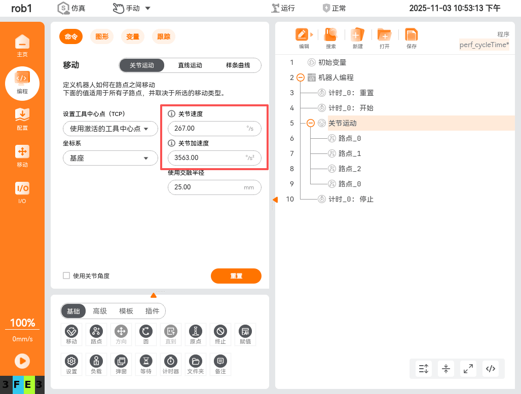
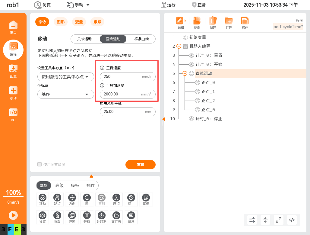
Goal: By reasonably adjusting the speed and acceleration parameters, make motions execute with optimal dynamic performance within a safe range.
velocity: Determines the overall motion execution time;
- Raising the speed limit can significantly shorten the time of large-displacement segments.
- However, avoid exceeding what the task requires to prevent emergency stops or vibration.
acceleration: Affects start/stop response and transitions between motions;
- Insufficient acceleration causes "slow starting" and "long pauses";
- Excessively high acceleration easily causes mechanical shock or control jitter.
Optimization suggestions:
- For frequent short-distance motions: moderately increase acceleration while keeping speed moderate.
- For long-distance translation: raise the speed limit and appropriately smooth the acceleration curve.
- Adjust based on actual load testing, keeping the overall jerk smooth.
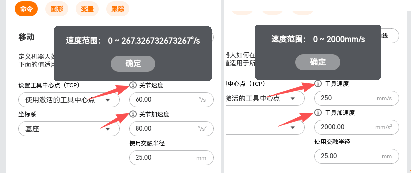
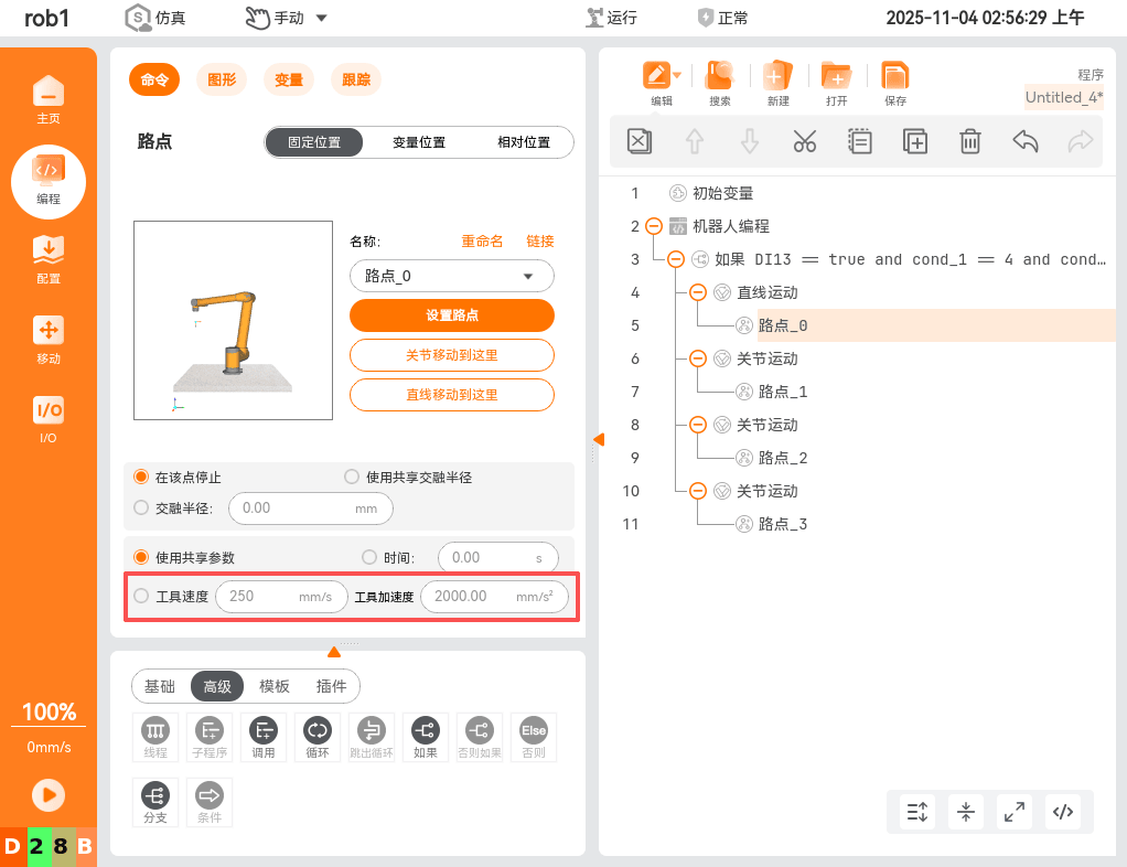
Viewing current speed and acceleration limits:
Examples:
(2) Blend Radius Optimization
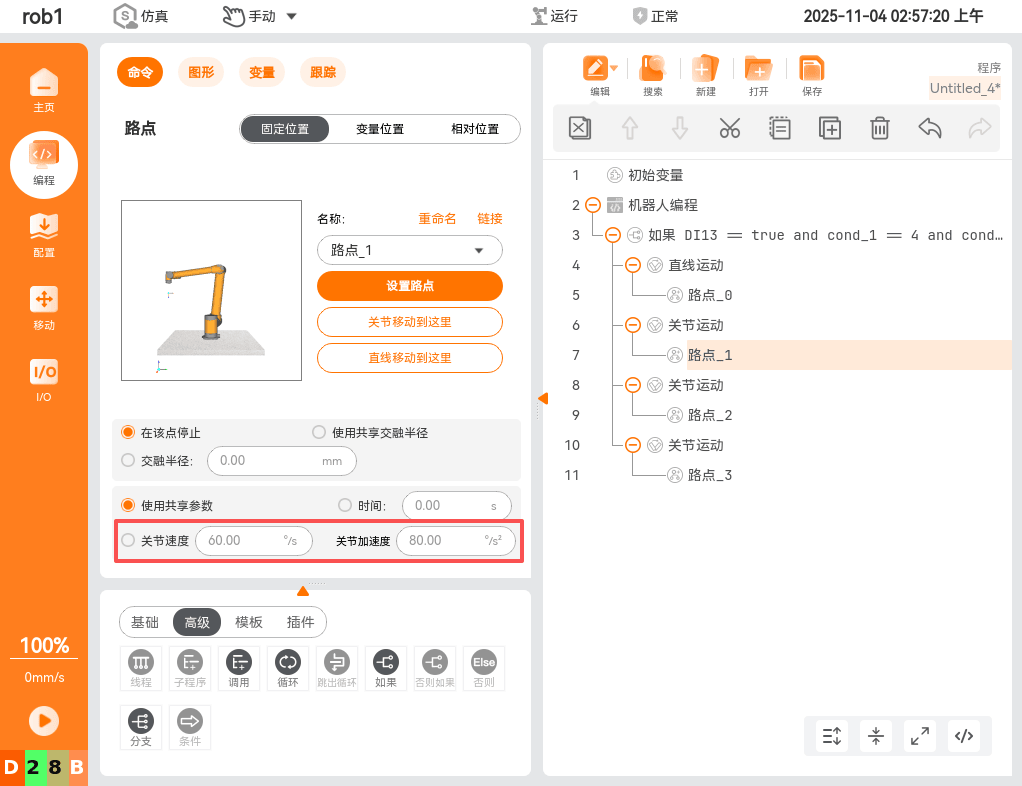
Goal: Reduce the sense of pause between motion segments, making the trajectory continuous and smooth.
Principle: Introduce an arc transition zone at the junction of two motion segments to avoid a complete stop before restarting.
Effect: Reduces sudden speed changes, improving visual and mechanical smoothness.
Note:
- The blend radius mainly improves motion smoothness rather than directly shortening the cycle time;
- An excessively large radius may affect accuracy when reaching the target and deviate from the target path;
- Key positioning points (grasping, assembly, etc.) should not use a blend radius.
Optimization suggestions:
| Motion type | Blend radius | Remarks |
|---|---|---|
| Continuous teaching points (no accuracy requirement) | Large | Improve smoothness |
| Ordinary transition points | Medium | Balance accuracy and smoothness |
| Precise positioning points (grasp/place) | 0 | Ensure complete stop |
Examples:
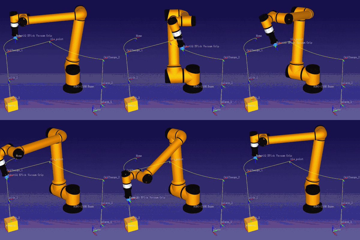
(3) Motion Mode Optimization (Synchronous Motion and Key Segment Decomposition)
Goal: By reasonably planning the overall motion mode, achieve the dual optimization of "speeding up non-critical segments + keeping critical segments safe". At the application level, the cycle time bottleneck often lies in "pick-and-place motions and waiting logic".
Optimization approach:
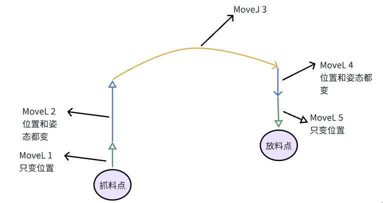
- Use joint motion moveJoint for aerial segments, or execute peripheral logic synchronously to speed up non-contact paths;
- Use linear motion moveLine for pick-and-place segments, decomposed into two phases, completing posture adjustment at a safe height to reduce the collision risk when approaching the workpiece.
① Fast Motion in Aerial Segments (moveJoint)
Effect: Using moveJoint in the transition segment "above the pick-up point → above the place point" can significantly shorten the traversal time.
Features:
- moveJoint's trajectory planning is done in joint space, so the speed limit is higher;
- Aerial segments do not need to keep the end effector on a straight line, so larger speed and acceleration can be used.
Suggestions:
- Gripper, vacuum, or peripheral handshake logic can be triggered simultaneously to achieve synchronous motion.
② Key Segment Decomposition (moveLine Two Phases)
To balance speed and safety, moveLine can be divided into:
- moveLine-1: position change only → descend or ascend along the Z axis without changing posture, quickly approaching the workpiece;
- moveLine-2: position + posture change → complete posture alignment within a safe height to prevent lateral collision.
The same applies to the placing end:
- moveLine-4: position + posture change (posture alignment in advance);
- moveLine-5: position change only (straight-line lowering).
Advantage: posture changes are completed in the air, and the path is stable when approaching the workpiece; Note: key points still require
blend radius = 0to ensure a stable stop and accurate positioning.
Examples:
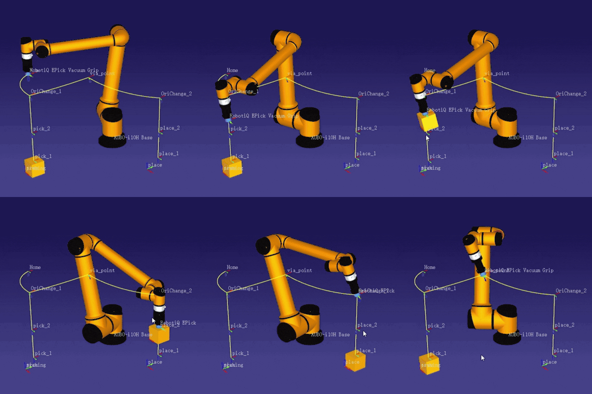
③ Synchronous and Parallel Logic
- Execute the aerial moveJoint in parallel with peripheral actions (such as gripper, signal waiting);
④ Parameters and Application Suggestions
| Phase | Recommended motion | Blend radius | Description |
|---|---|---|---|
| Aerial traversal | moveJoint | Large | Speed-up segment, can parallelize peripherals |
| Posture adjustment at safe height | moveLine | Small | Small-range posture change |
| Pick-and-place straight-line segment | moveLine | 0 | Accuracy first, complete stop |
| Key points | moveLine | 0 | Blend prohibited, ensure positioning |
4.2 Wait Logic Optimization
-- Original: fixed delay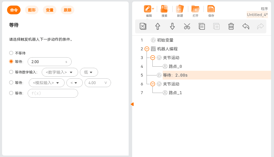
-- Optimized: condition + timeout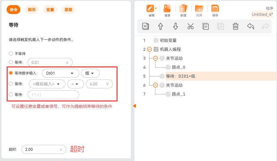
4.3 Asynchronous Signal Optimization
4.3.1 Asynchronous Signal Optimization -- Motion Events
- Triggers can be fired during motion based on motion time, progress, or distance to trigger corresponding variables and signals without interrupting blending.
For details, see: Application Note 65 - Motion Event Triggering Guide
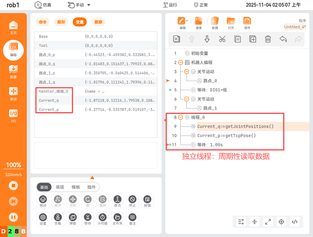
4.3.2 Asynchronous Signal Optimization -- IO Monitoring
- Put IO monitoring into an independent thread so it does not block the main logic.
- Read/write signals in batches to reduce communication cycles.
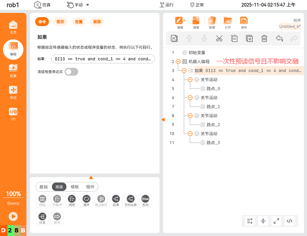
4.4 Program Logic Optimization
-- Original: redundant judgment logic
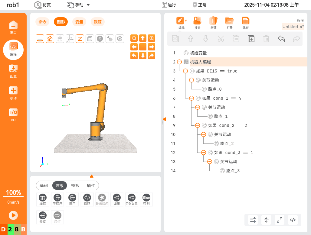
-- Optimized: judgment logic pre-reading
6. Conclusions and Suggestions
- Main causes: pauses in motion transitions, excessive logic waiting for signals, redundant logic structure
- Main improvement methods: continuous motions, asynchronous logic, simplified logic structure