
Force Control Plugin User Manual
1. Force Control Plugin Introduction
1.1 Feature Introduction
This Force Control plugin is used to be compatible with and adapt to all force sensors, and to use force sensors to implement features such as adaptive robot arm operation and zero-force control under the ARCS system. The plugin currently supports the robot arm's built-in sensor, Kunwei, Yuli, and Xinjingcheng sensors.
1.2 Plugin Deployment Introduction
1.2.1 Sensor Plugin Deployment
Using the Force Control plugin requires the ARCS host software version to be 0.29.2-beta.15 or later, and requires installing the Force Control plugin and configuring the corresponding parameters. All of the above can be deployed with one click using the plugin deployment archive. Please contact AUBO to obtain the plugin deployment archive. Extract the deployment archive to any path, use the terminal to navigate to the extracted file path, and enter sh install.sh followed by the sensor type command to run the installation script, which completes the deployment of the Force Control plugin and the sensor plugin as well as the parameter write-in to the configuration file.
The currently supported sensor types are: kw, xinjingcheng, yuli.
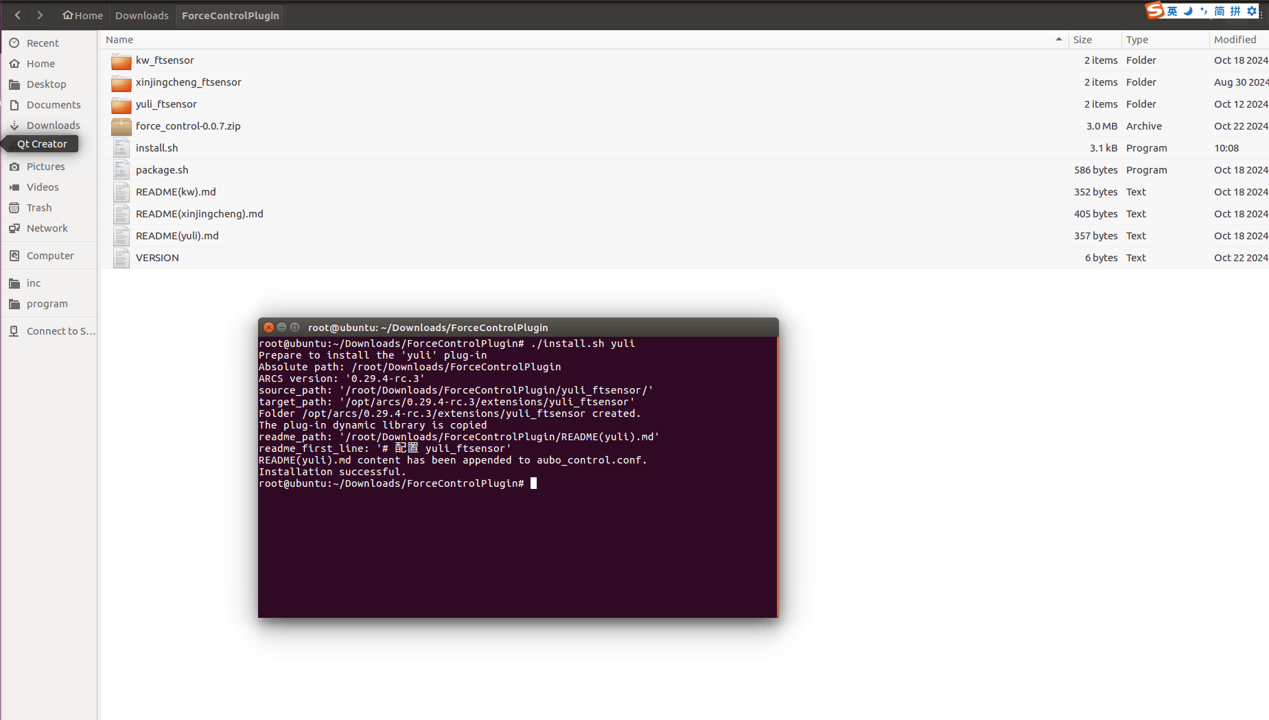
When you see the prompt message shown in the figure, the installation is complete.
Note
After switching to a new ARCS version for the first time, you need to redeploy.
1.2.2 Force Control Plugin Deployment
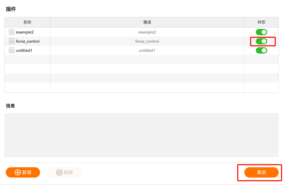
Open the ARCS host software, click "Settings > System > Plugins > Add" in the upper right corner, select the plugin archive for the corresponding version, and click [Select] to add it.
After adding the plugin, check the Force Control plugin and click [Restart] to complete the plugin activation.
2. Plugin Operation Interface Introduction
2.1 Sensor Configuration Interface
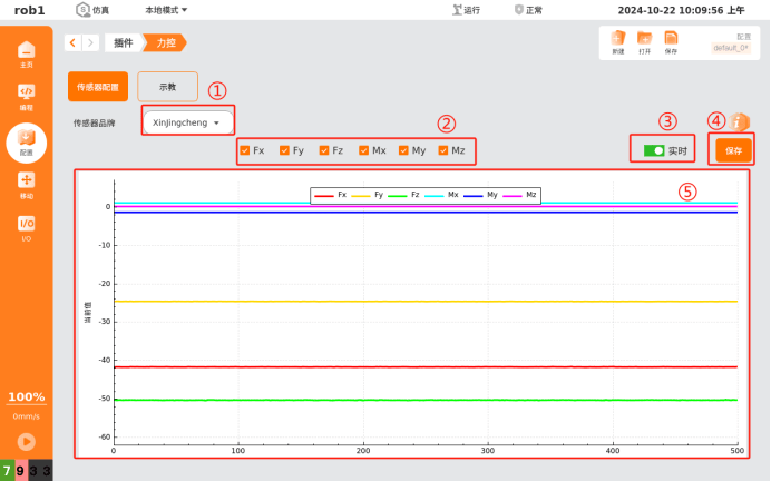
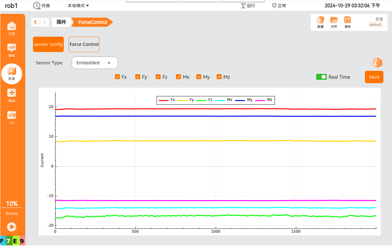
The sensor configuration interface is shown in the figure above.
[Sensor Brand]: used to select the sensor brand in use. It currently supports the built-in sensor, Kunwei, Yuli, and Xinjingcheng sensors. After selecting the sensor, the sensor requests data immediately.
You can check the checkboxes to show or hide the corresponding data.
[Real-time]: check [Real-time] to display the force data in the chart below.
[Save]:
Without checking Real-time, clicking [Save] saves all the data from the beginning of the request.
With Real-time checked, clicking [Save] changes the button state to Stop, and data saving begins at this point. Clicking [Stop] again stops saving, and the saved data is the data between the two clicks.
The file is saved in the /root/arcs_ws/extensions/force_control directory. The first six groups of data in the file are the pose of the TCP in use, and the last six groups are the forces and torques in the x, y, and z directions.
Note
The file save path and the chart display length can be modified in the
/root/arcs_ws/program/default.insfile; the configuration parameters are consistent with the steps above.The chart displays in real time the force data based on the Base coordinate system with the bias and load removed. It supports displaying six groups of data — Fx, Fy, Fz, Mx, My, Mz — representing the forces and torques in the x, y, and z directions, respectively.
The following introduction uses the Xinjingcheng sensor as an example; the usage of other sensors is similar.
2.2 Teaching Interface
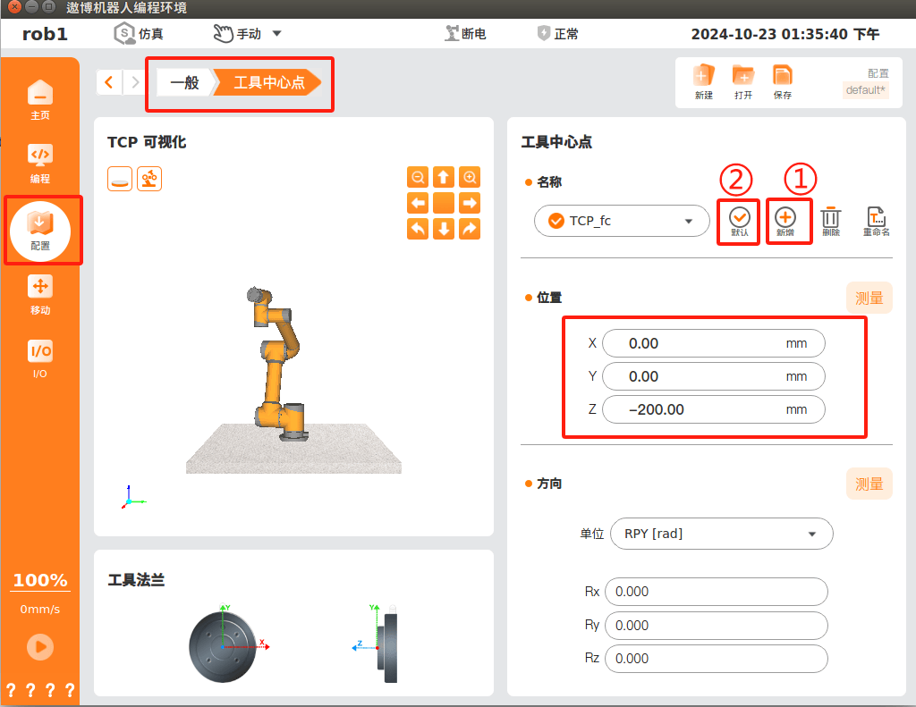
Before using the corresponding functions of the Force Control plugin, you need to first add a TCP under "Configuration > General > Tool Center Point". Click [Add], then enter the offset of the tool center point relative to the flange center, and set this TCP as [Default], as shown in the figure.
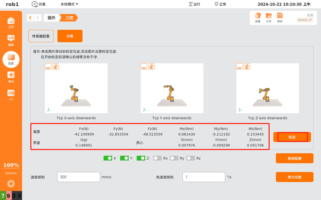
Then calibrate the sensor; click [Calibrate] to calibrate automatically.
Note
Before calibration, make sure the sensor configuration interface can normally read force data, and make sure that the robot arm has no interference and is not affected by collisions during the calibration process. After calibration ends, the parameter boxes show the bias, mass, and center-of-mass data; reset the load parameters as needed.
2.3 Calibration Pose Interface
There are three default poses for calibration: the TCP's positive X axis pointing downward, the TCP's positive Y axis pointing downward, and the TCP's positive Z axis pointing downward, corresponding to the three images respectively.
Clicking the three images on the teaching interface navigates to the calibration pose interface.
Double-clicking the three images on the teaching interface lets you set the calibration pose yourself; move to the desired pose and click [Confirm] to complete the modification, which is saved automatically.
3. Force Control Plugin Program Node Introduction
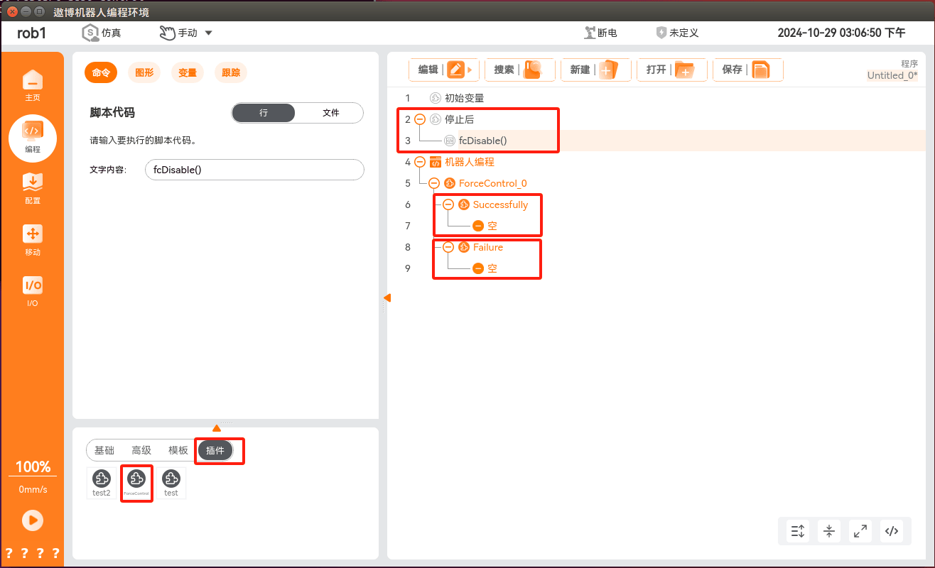
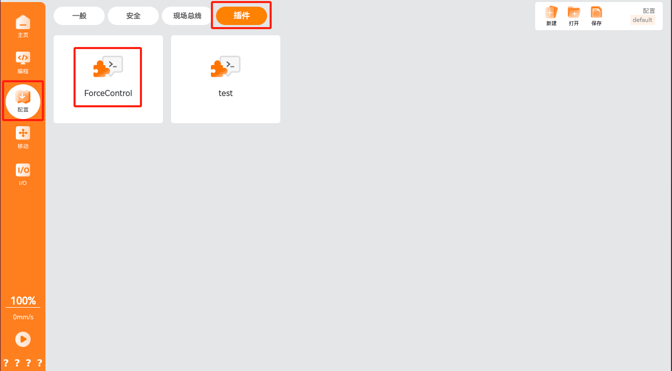
To add a force control condition in the program node, click "Programming > Plugins > ForceControl" to add the force control condition. This condition consists of the force control condition configuration and the flow implementation after normal/abnormal exit from the force control condition.
Note
A flow must be added after both normal and abnormal exit from the force control condition, and the script fcDisable() should also be added after the program stops, to avoid the force control not being turned off after an abnormal exit.
3.1 Basic Configuration Interface
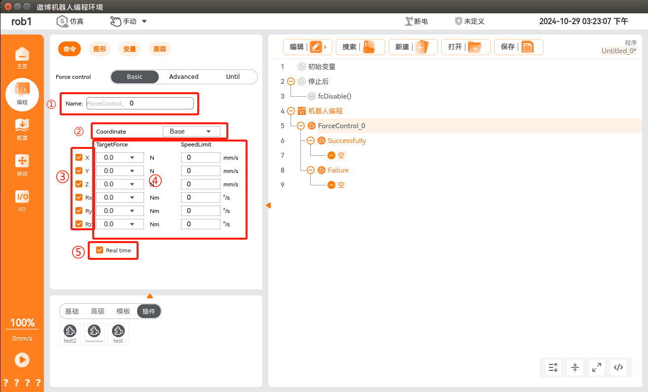
You can customize and modify the node name.
Select the reference coordinate system; generally a user coordinate system or a tool coordinate system is selected as the reference coordinate system.
Force control enabling direction; if the force in a direction is not needed, you can uncheck it.
You can set the target force and the corresponding speed limit.
In the "Configuration > Plugins > Force Control > Sensor" configuration interface, you can view the real-time force control data, as shown below. The reference coordinate system is the coordinate system set in step 2 of the figure above.
3.2 Advanced Configuration Interface
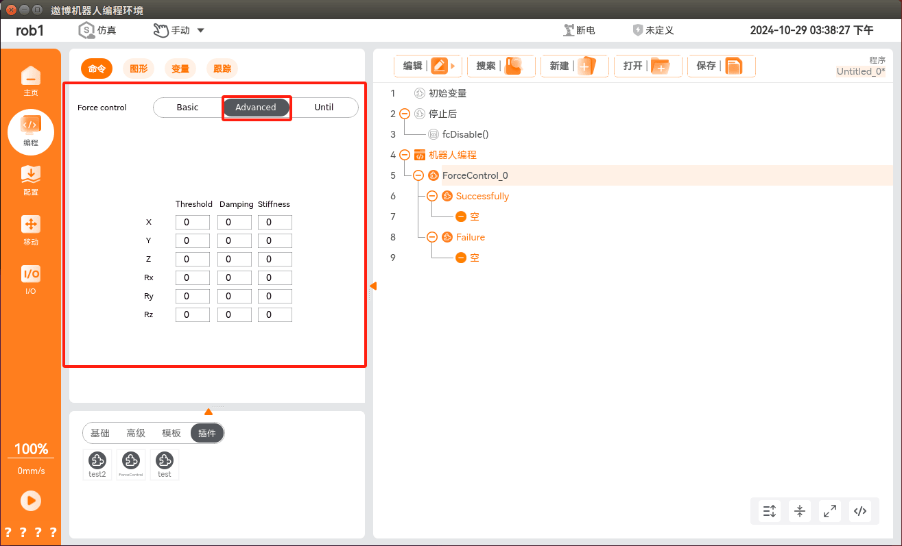
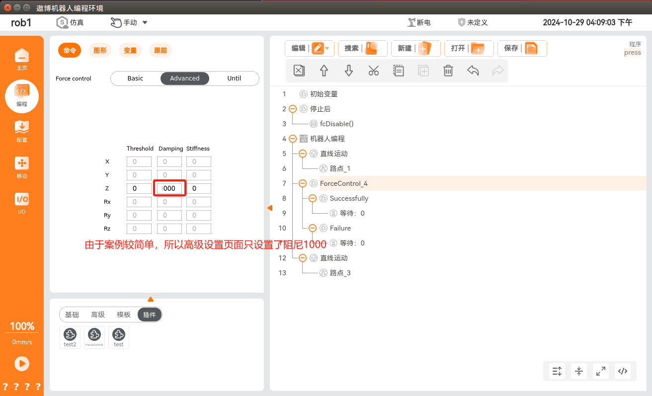
The advanced configuration interface lets you configure the threshold, damping, and stiffness parameters in six directions. Whether the parameters in a direction can be modified depends on whether the checkbox for the corresponding direction in the teaching interface is checked.
Threshold: modifying it in this interface has no effect for now; it needs to be modified in the
/root/arcs_ws/config/aubo_control.conffile.Damping: describes how much resistance there is to pushing the robot. The resistance does not increase with the distance between the robot and the reference point; instead, it usually increases with the robot's speed.
Stiffness: describes the strength with which the robot tries to return to the reference point. The higher the value, the stronger the spring effect. Setting this value to zero produces no spring effect, and the robot floats along the selected direction.
3.4 Stop Condition Interface
The stop condition interface is divided into normal exit conditions and abnormal exit conditions.
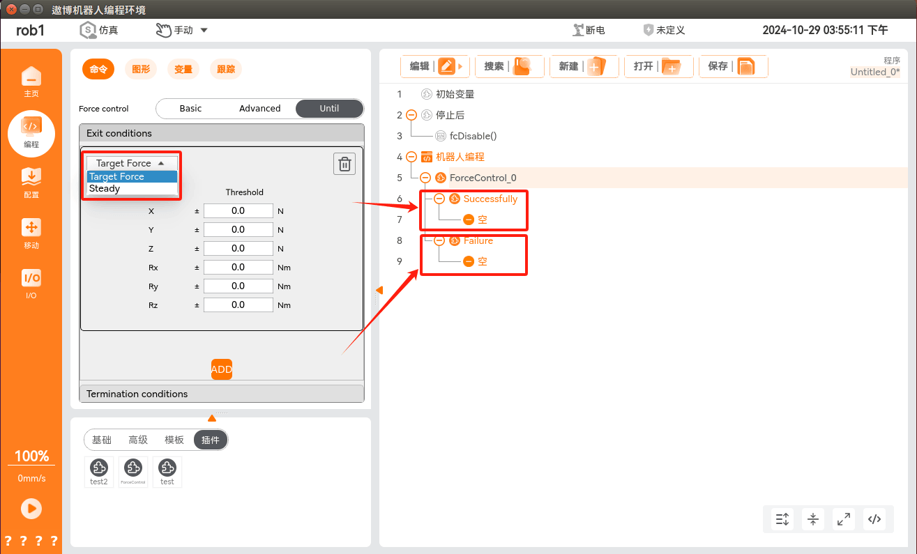
Among the normal exit conditions, target force and steady state are available. When the condition is met, the robot exits the force control condition and enters the force control normal exit flow.
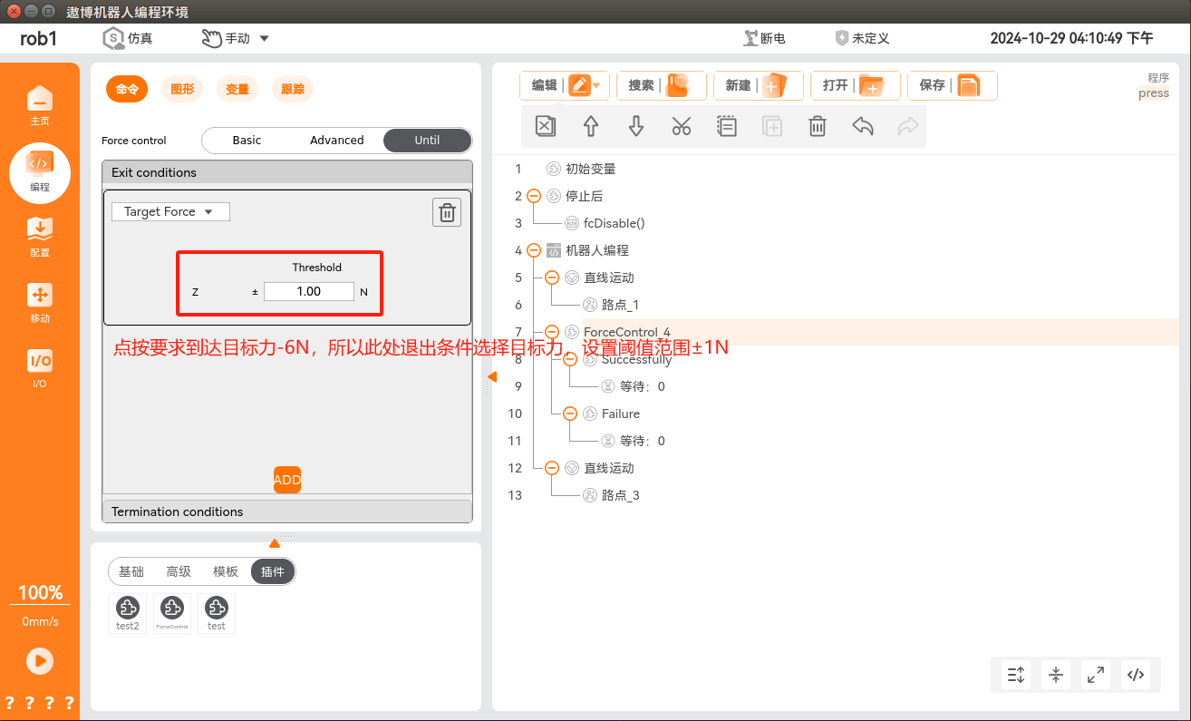
Selecting target force means that the threshold sizes set by the target force are met in the six directions.
Selecting steady state means that the robot arm's motion queue is empty and it remains relatively still.
Among the abnormal exit conditions, timeout is the only available option. When the condition is met, the robot exits the force control condition and enters the force control abnormal exit flow. Selecting timeout means that after force control is enabled, the set time has elapsed without exiting force control.
4. Examples
4.1 Press
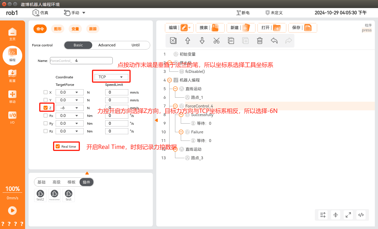
Requirement: the pen at the end of the robot arm contacts the target plane vertically with a force of 6N ± 1N, then retracts after contact.
Approach: during pressing, if the speed of the force control stage is too fast, the target force will overshoot. To avoid this without reducing the cycle time, choose to enable force control 3 mm above the target point, exit force control after reaching the target force, and lower the speed of the force control stage. For the other stages, choose linear or joint motion, and set the speed according to the actual situation.
Robot arm press execution example:

Press example related files:
4.2 Multi-Press
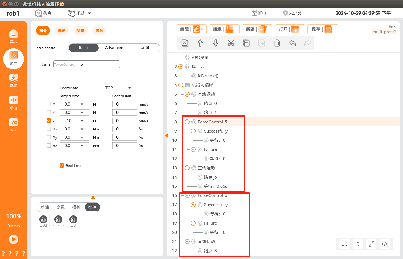
Requirement: the pen at the end of the robot arm contacts the target plane vertically with a force of 10N ± 1N, lifts up, then presses down again with a target force of 10N, and retracts after contact.
Approach: the process is similar to Press, adding a lift and press process on top of Press.
Parameter settings:
Coordinate system: TCP.
Force control enabling direction: Z.
Target force: -10N.
Damping: 1000, which can be modified according to the actual site conditions.
Exit condition: reaching the target force ±1N.

Multi-press example related files:
4.3 Draw a Straight Line
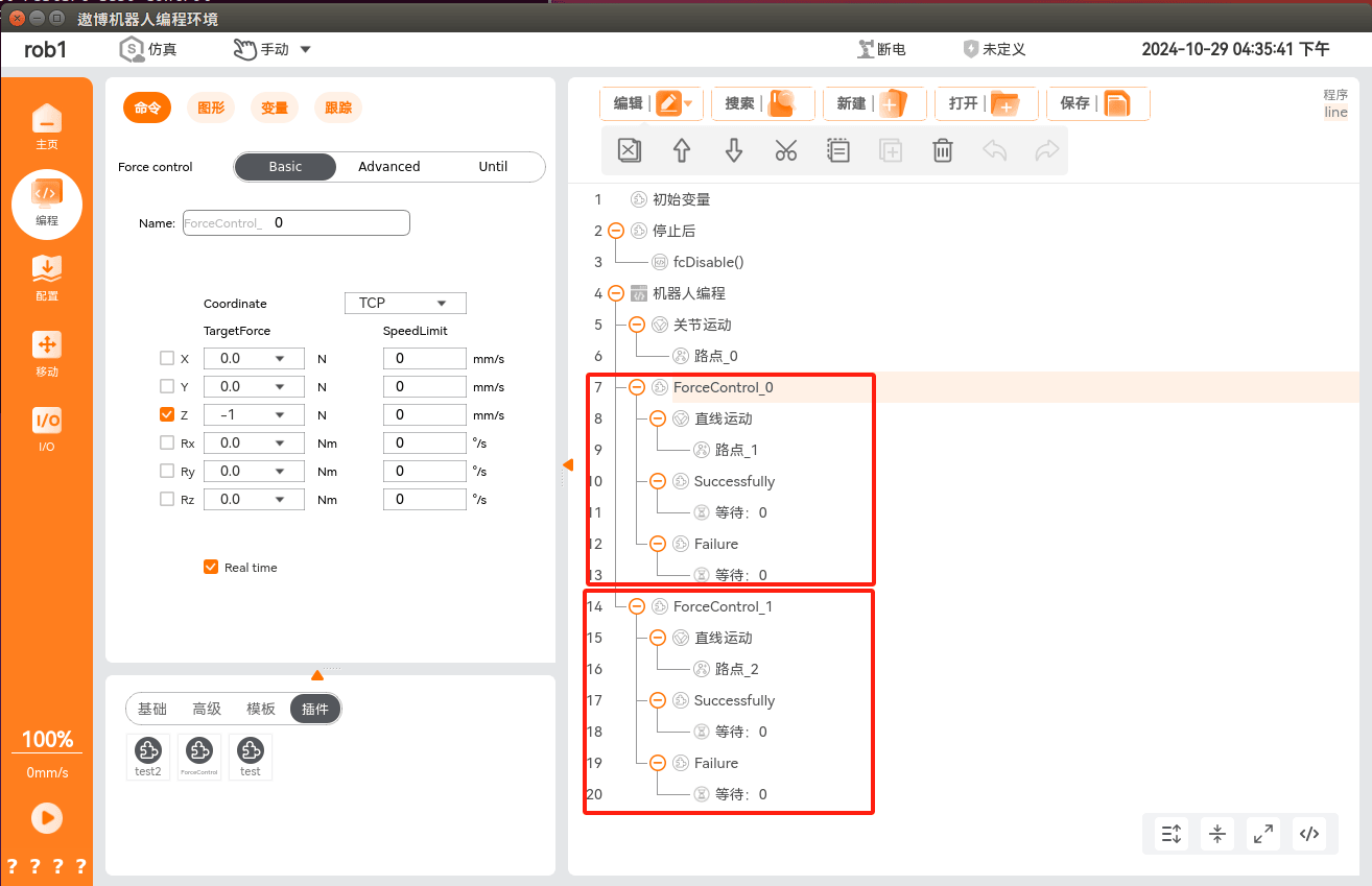
Requirement: the pen at the end of the robot arm contacts the target plane vertically with a force of 1N ± 0.5N, and draws a straight line on the plane with a force of 1N ± 0.5N.
Approach: the first stage process is similar to Press. After contacting the plane with a target force of 1N, exit force control, set another point on the plane, enable force control, and move linearly while maintaining the 1N force. Alternatively, the two force control stages can be combined into one: after reaching the target force, draw the straight line directly without turning off force control during the process.
Parameter settings:
Coordinate system: TCP.
Force control enabling direction: Z.
Target force: -1N.
Damping: 1000, which can be modified according to the actual site conditions.
Exit condition: the first stage reaches the target force ±0.2N, and the second stage exits at steady state.
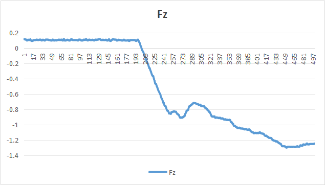
Straight-line drawing example related files:
4.4 Draw a Circle
Requirement: the pen at the end of the robot arm contacts the target plane vertically with a force of 1N ± 0.5N, and draws a circle on the plane with a force of 1N ± 0.5N.
Approach: the first stage process is similar to Press. After contacting the plane with a target force of 1N, enable the second stage of force control, calibrate the three points of the circle, and draw a circle with a target force of 1N ± 0.5N.
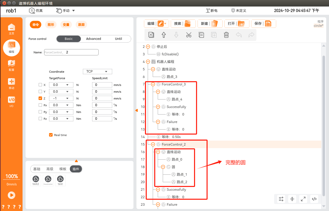
Parameter settings:
- Coordinate system: TCP.
- Force control enabling direction: Z.
- Target force: -1N.
- Damping: 1000, which can be modified according to the actual site conditions.
- Exit condition: reaching the target force ± 0.2N.
Robot arm circle-drawing execution example:
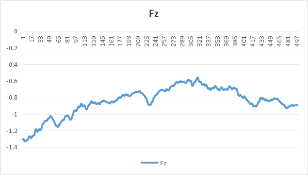
- Circle-drawing example related files:
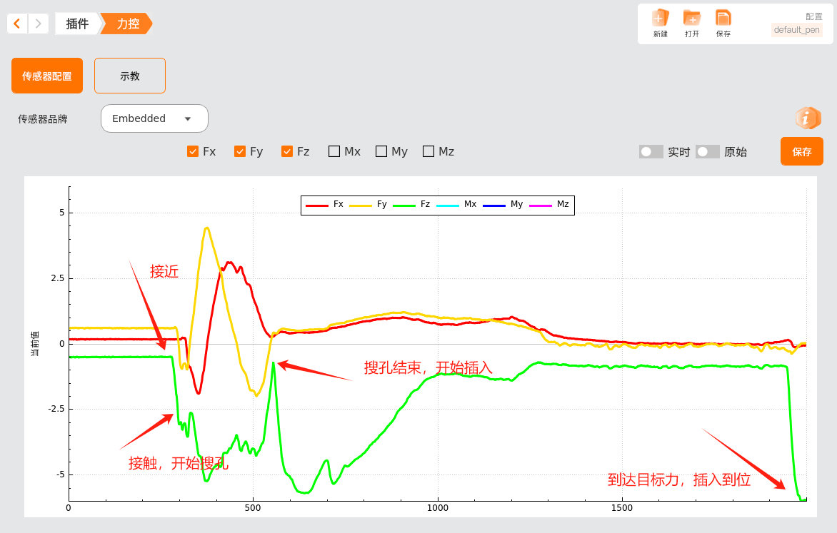
4.5 Hole Search
Requirement: the workpiece at the end of the robot arm contacts the target hole vertically and aligns with the hole to complete insertion.
Approach:
The first stage is approaching, similar to Press; after contacting the plane with a target force of 1N, stop force control.
The second stage is spiral hole search, performing spiral hole search with a target force of 4N. When the workpiece finds the hole, the Z-direction target force suddenly decreases to within 2N, triggering the current stage's force control stop condition.
The third stage is insertion: set the Z-direction target force to 6N and the XY-direction target force to 0, so that the workpiece can be inserted along the hole.
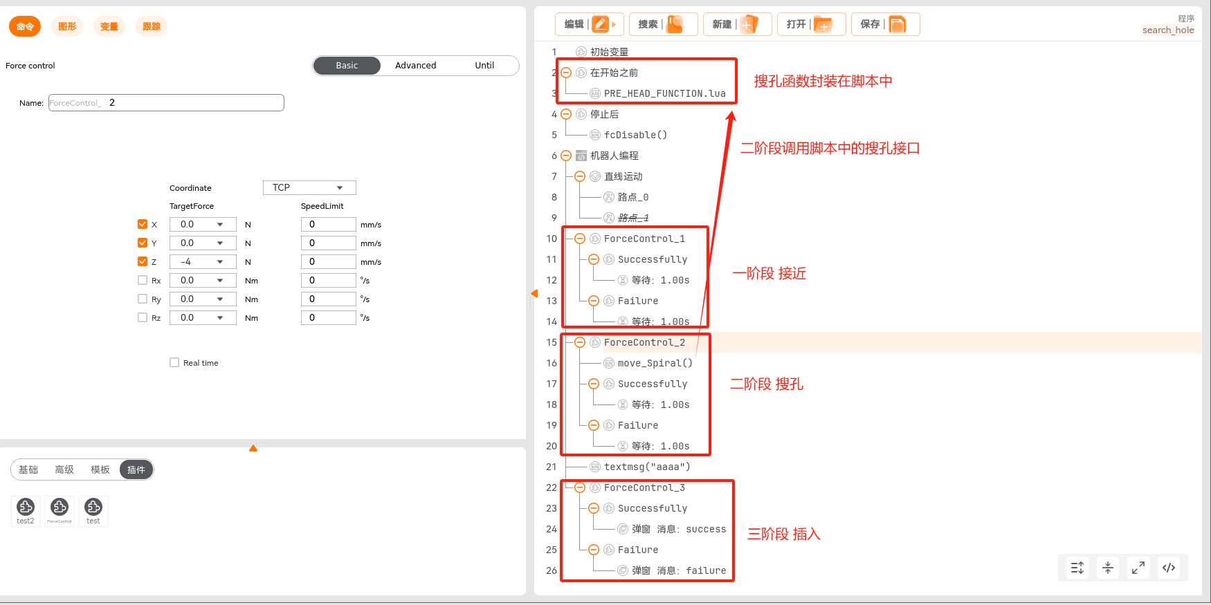
Parameter configuration:
- Stage 1, approaching:
- Coordinate system: TCP.
- Force control enabling direction: Z.
- Target force: -2N.
- Damping: 1000, which can be modified according to the actual site conditions.
- Exit condition: reaching the target force ±0.2N.
- Stage 2, spiral hole search:
- Coordinate system: TCP.
- Force control enabling direction: Z.
- Target force: -4N.
- Damping: 2000, which can be modified according to the actual site conditions.
- Normal exit condition: maintaining the steady state.
- Abnormal exit condition: target force, Z direction -2N~2N, with "outside" checked.
- Stage 3, insertion:
- Coordinate system: TCP.
- Force control enabling direction: XYZ.
- Target force: 0 in the XY direction, -6N in the Z direction.
- Damping: 1000, 1000, 2000, which can be modified according to the actual site conditions.
- Normal exit condition: maintaining the steady state.
- Stage 1, approaching:
Robot arm hole-search execution example:
Hole-search example related files: