
RS485 Test
1 Control Cabinet Interface Board Pass-through RS485 Test
Interface board pass-through RS485 means that RS485 is connected to the interface board and can be configured by software. It has a unified mapped port number: ttyIfaceBrd
Note: The interface board pass-through 485 function must be tested with ARCS: 0.31.0 branch together with firmware: v1.1.1 or later. Versions earlier than v1.1.1 do not have the interface board pass-through 485 function.
1.1 Preparing Tools
USB-to-RS485 serial cable, XCOM V2.3, Dupont wires (two)
XCOM V2.3: https://download.aubo-robotics.cn/3rd-party/XCOM_V2.3.zip
1.2 Connecting Cables
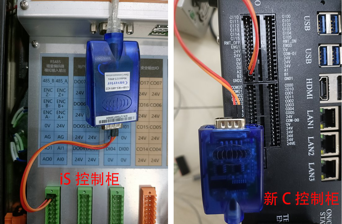
Connect a nine-pin USB-to-485 cable to the control cabinet through Dupont wires. For iS wiring, connect pin 1 to 485_A and pin 2 to 485_B. For the new C control cabinet, connect pin 1 to A2 and pin 2 to B2, as shown in the figure below.
Currently, only the iS control cabinet and new C control cabinet support the interface board pass-through RS485 function. Other models do not support it for the time being. If you need to use the RS485 function, use native RS485 (RS485 connected to the industrial PC) or USB-to-RS485.
| iS Control Cabinet | New C Control Cabinet | |
|---|---|---|
| 485 IO Silkscreen | 485_A, 485_B | A2, B2 |
| Mapped Port Number | ttyIfaceBrd | ttyIfaceBrd |
1.3 Configuring Serial Port Information
The default parameters of interface board pass-through RS485 are baud rate: 115200, stop bits: 1, and no parity. To modify them, add configurations in the
aubo_control.conffile or configure the parameters in real time through the host computer.
1.3.1 Configuration Method 1
Add the following configuration to the [RobotHw.options] item under [[RobotHw]] in /root/arcs_ws/aubo_control.conf. If it is not added, the defaults are baud rate 115200, stop bit 1, and no parity.
[RobotHw.options.ifacebrd_serial]
		baudrate = "115200" # Baud rates supported by the control cabinet interface board pass-through RS485 serial port: "4800" "9600" "19200" "38400" "57600" "115200"
        stopbits = "1" # Stop bits supported by the control cabinet interface board RS485 serial port: "1" "0.5" "1.5" "2"
        parity = "none" # Parity bits supported by the control cabinet interface board pass-through RS485 serial port: "none" "even" "odd"
The configuration position in /root/arcs_ws/aubo_control.conf is shown below.
[[RobotHw]]
location = "extensions/hardware_interface/hardware_interface.so"
bundle = "robot_driver"
alias = "robot_driver1"
[RobotHw.options]
    friction_model_version = 3
    port_mac = "01:01:01:01:01:01"
    joints = [ 1, 2, 3, 4, 5, 6 ]
    slave_joints = [ 11, 12, 13, 14, 15, 16 ]
    tool = 9
    base = 8
    master_board = 1
    slave_board = 2
    sync_period = 5000
    can_port_mode = "DUAL_CAN_INV"
    tool_bus_type = 1 # Tool-end serial port type: 0-modbus 1-485 serial port 2-force sensor
    baudrate = "115200" # Baud rates supported by the tool-end serial port: "4800" "9600" "19200" "38400" "57600" "115200"
    stopbits = "1" # Stop bits supported by the tool-end serial port: "1" "0.5" "1.5" "2"
    parity = "none" # Parity bits supported by the tool-end serial port: "none" "even" "odd"
     [RobotHw.options.ifacebrd_serial]
			baudrate = "115200" # Baud rates supported by the control cabinet interface board pass-through RS485 serial port: "4800" "9600" "19200" "38400" "57600" "115200"
    	stopbits = "1" # Stop bits supported by the control cabinet interface board RS485 serial port: "1" "0.5" "1.5" "2"
    	parity = "none" # Parity bits supported by the control cabinet interface board pass-through RS485 serial port: "none" "even" "odd"
After the configuration is complete, restart aubo_control.
systemctl restart aubo_control1.3.2 Configuration Method 2
Configure in real time through the host computer. Use a browser and TCP debugging assistant to send scripts. For usage, refer to 27 Using a Browser and TCP Debugging Assistant to Send Scripts · AUBO Application Notes
Server address: ws://192.168.10.150:9012 Use this port to send scripts. 192.168.10.150 is the IP address of the current device.
{"jsonrpc": "2.0", "id": "ri1godwu", "method": "rob1.RobotConfig.setHardwareCustomParameters", "params":["[ifacebrd_serial]\nbaudrate = \"115200\"\nstopbits = \"1\"\nparity = \"none\"\n"]}1.4 Performing the Test
Use the
ls /dev/tty*command. One more item,ttyIfaceBrd, appears in the device list, as shown in the figure below.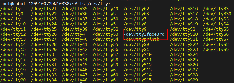
Enter
cutecomin the terminal and press Enter to open thecutecomtool. If it cannot be opened, enter the following command to install it and then open it again.You can also use the command
echo "test" > /dev/ttyIfaceBrdto directly send data to the computer'sXCOM V2.3serial assistant, and usecat /dev/ttyIfaceBrdto view the data sent by the serial assistant. Note: Thecutecomtool in the 16.04 system is consistent with this document and can be used for normal testing. If the system version is 22.04, the/dev/ttyIfaceBrdserial port cannot be selected incutecomfor testing, and only commands can be used for testing.sudo apt-get install cutecom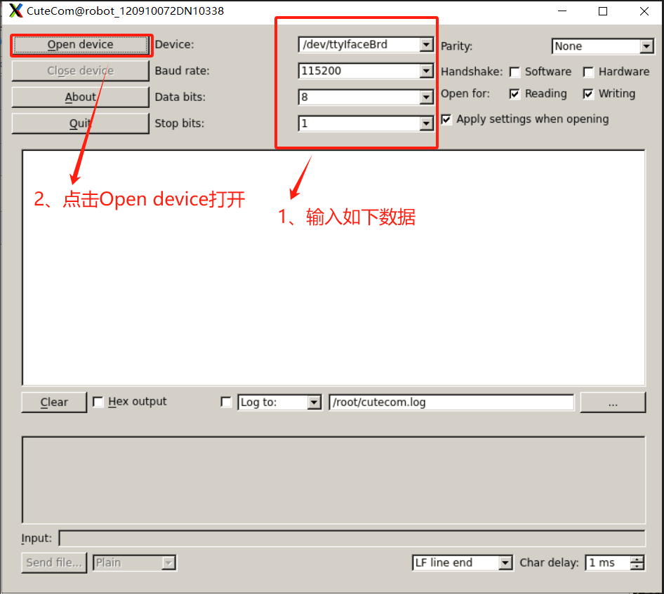
Double-click the serial assistant
XCOM V2.3on the laptop to open it. Select the serial port (if there is no serial port, communication is not established or the cable is connected incorrectly). Set the baud rate, stop bits, data bits, and parity bits as shown in the figure. ClickOpen Serial Port.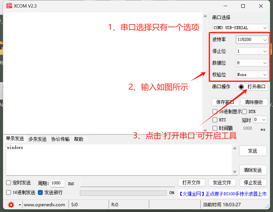
Use
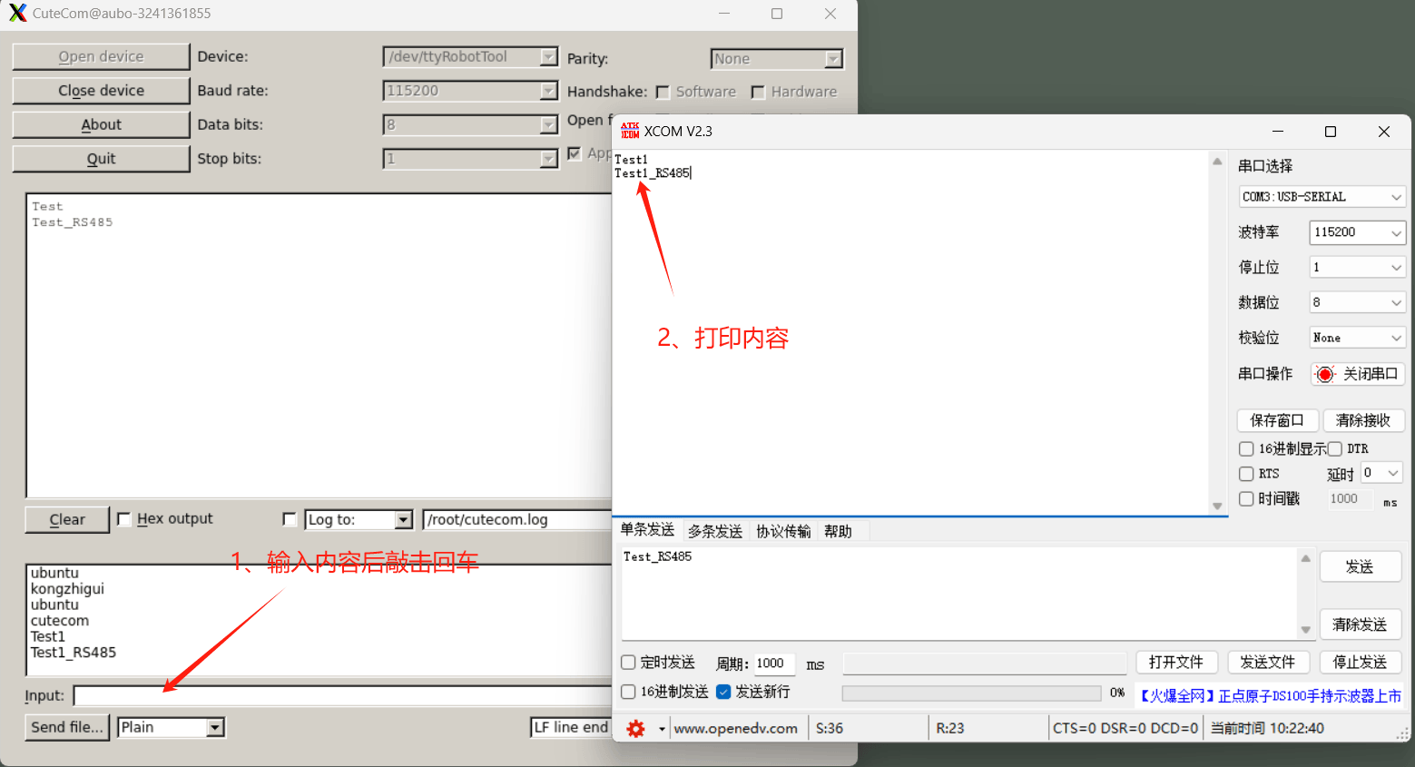
XCOM V2.3on the laptop (Windows system) to send information, and the debugging assistantcutecomat the other end can print the corresponding information. Similarly, use the debugging assistantcutecomto send information, andXCOM V2.3also prints the information.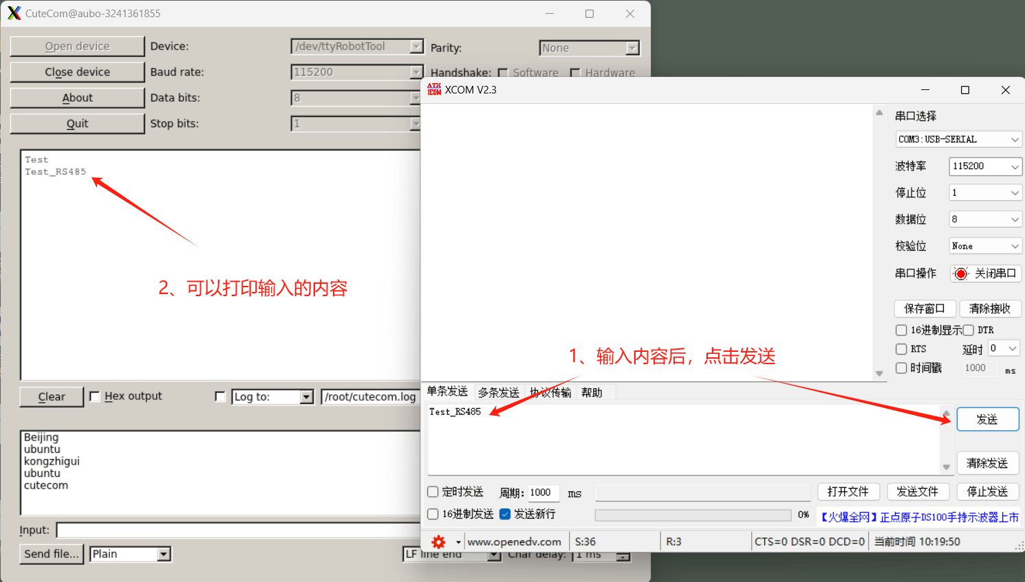
2 Control Cabinet Native RS485 Test
Control cabinet native 485 means that the RS485 serial port is connected to the industrial PC. The RS485 serial port numbers differ for different control cabinets.
2.1 Preparing Tools
USB-to-RS485 serial cable, XCOM V2.3, Dupont wires (two).
XCOM V2.3: https://download.aubo-robotics.cn/3rd-party/XCOM_V2.3.zip
2.2 Connecting Cables
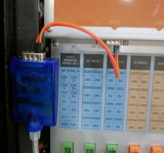
Using the iS control cabinet as an example, connect a nine-pin USB-to-RS485 cable to the control cabinet through Dupont wires. The wiring method is pin 1 to pin 1 and pin 2 to pin 2, as shown in the figure below.
The RS485 serial port information for other control cabinets is shown in the table below.
| IS | Improved Control Cabinet | New C | S/ES3/ES5 | Mini Control Box | |
|---|---|---|---|---|---|
| 485 IO Silkscreen | RS485 | Modbus RTU | A1 B1 | 485+ 485- | COM2 |
| Port Number | ttyS2 | ttyS2 | ttyS0 | ttyS7 | ttyS2 |
| UI Display | RS485 | Modbus RTU | [I/O] A1, B1 | [I/O] 485+, 485- | COM2 |
2.3 Configuring Parameters
Enter the terminal of the control cabinet and set the serial port baud rate, data bits, parity, and stop bits.
Default settings: baud rate 115200, 8 data bits, no parity bit, and 1 stop bit.
stty -F /dev/ttyS2 115200 cs8 -parenb -cstopb/dev/ttyS2indicates the path of thettyS2serial device file.115200indicates the baud rate.cs8indicates 8 data bits.-parenbindicates no parity bit. #parenb-paroddis even parity,parodd parodd: odd parity.-cstopbindicates that the stop bit is 1 bit. #cstopbmeans the stop bit is 2.
- Open the terminal of the control cabinet and query the serial port parameters.
stty -F /dev/ttyUSB0 -a
2.4 Performing the Test
- Enter
cutecomin the terminal and press Enter to open thecutecomtool. If it cannot be opened, enter the following command to install it and then open it again.
You can also use the command
echo "test" > /dev/ttyS2to directly send data to the computer'sXCOM V2.3serial assistant, and usecat /dev/ttyS2to view the data sent by the serial assistant.
sudo apt-get install cutecom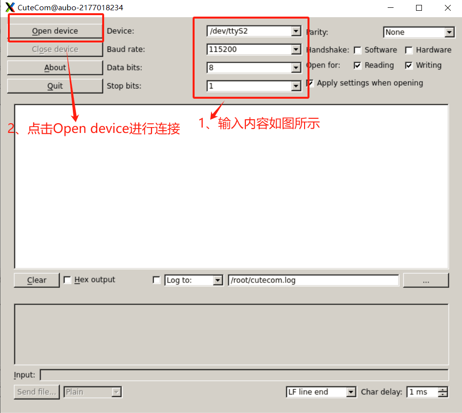
- Double-click the serial assistant
XCOM V2.3on the laptop to open it. Select the serial port (if there is no serial port, communication is not established or the cable is connected incorrectly). Set the baud rate, stop bits, data bits, and parity bits as shown in the figure. ClickOpen Serial Port.
- Use
XCOM V2.3on the laptop (Windows system) to send information, and the debugging assistantcutecomat the other end can print the corresponding information. Similarly, use the debugging assistantcutecomto send information, andXCOM V2.3also prints the information.
3 Tool-end RS485 Test
Tool-end 485 refers to the RS485 serial port on the end of the robotic arm. Robotic arms with tool-end RS485 generally have two I/O ports at the tool end, and the four-core one is the tool-end RS485 communication interface.
3.1 Preparing Tools
Four-core 485 tool-end cable, USB-to-RS485 serial cable, XCOM V2.3, cutecom
Serial assistant downloaded on the laptop (Windows system): XCOM V2.3 https://download.aubo-robotics.cn/3rd-party/XCOM_V2.3.zip
Download for the control cabinet (Ubuntu system): cutecom
sudo apt-get install cutecom3.2 Connecting Cables
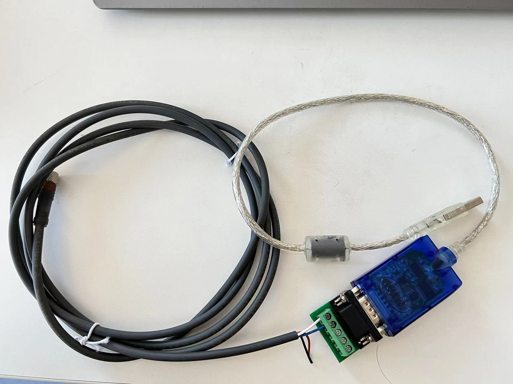
Four-core tool-end cable wire sequence description:
| Network Definition | Cable Color |
|---|---|
| VCC | Brown |
| GND | Black |
| T/R+ | White |
| T/R- | Blue |
485-to-USB cables may come from different manufacturers, and the positive/negative silkscreen may be 485+/485-, A/B, TR+/TR-, or even D+/D-. Wire according to the actual situation.
3.3 Configuring Parameters
Modify /root/arcs_ws/aubo_control.conf as configured below: the tool end is 485, baud rate 115200, stop bit 1, and no parity.
tool_bus_type = 1 # Tool-end serial port type: 0-modbus 1-485 serial port 2-force sensor
baudrate = "115200" # Baud rates supported by the tool-end serial port: "4800" "9600" "19200" "38400" "57600" "115200"
stopbits = "1" # Stop bits supported by the tool-end serial port: "1" "0.5" "1.5" "2"
parity = "none" # Parity bits supported by the tool-end serial port: "none" "even" "odd"
Example:
[[RobotHw]]
location = "extensions/hardware_interface/hardware_interface.so"
bundle = "robot_driver"
alias = "robot_driver1"
[RobotHw.options]
    friction_model_version = 3
    bus_driver = "pcap:enp2s0"
    port_mac = "01:01:01:01:01:01"
    joints = [ 1, 2, 3, 4, 5, 6 ]
    slave_joints = [ 11, 12, 13, 14, 15, 16 ]
    tool = 9
    base = 8
    master_board = 1
    slave_board = 2
    sync_period = 5000
    can_port_mode = "DUAL_CAN_INV"
        tool_bus_type = 1 # Tool-end serial port type: 0-modbus 1-485 serial port 2-force sensor
        baudrate = "115200" # Baud rates supported by the tool-end serial port: "4800" "9600" "19200" "38400" "57600" "115
        200" "230400" "460800"
        stopbits = "1" # Stop bits supported by the tool-end serial port: "1" "0.5" "1.5" "2"
        parity = "none" # Parity bits supported by the tool-end serial port: "none" "even" "odd"
3.4 Performing the Test
- After the configuration is complete, restart
aubo_control.
systemctl restart aubo_control- After power-on and brake release, one more item,
ttyRobotTool, appears in the /dev device list.
ls /dev/tty*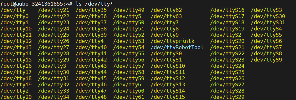
After the communication cable is assembled, connect one end to the end of the robotic arm and the other end to the laptop.
Open
cutecomon the control cabinet. Entercutecomin the terminal and press Enter to open it. Note: Thecutecomtool in the 16.04 system is consistent with this document and can be used for normal testing. If the system version is 22.04, the/dev/ttyRobotToolserial port cannot be selected incutecomfor testing, and only commands can be used for testing.
cutecom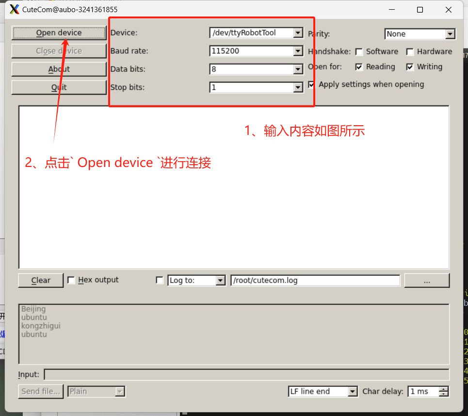
- Double-click the serial assistant
XCOM V2.3on the laptop to open it. Select the serial port (if there is no serial port, communication is not established or the cable is connected incorrectly). Set the baud rate, stop bits, data bits, and parity bits as shown in the figure. ClickOpen Serial Port.
- Use
XCOM V2.3on the laptop (Windows system) to send information, and the debugging assistantcutecomat the other end can print the corresponding information. Similarly, use the debugging assistantcutecomto send information, andXCOM V2.3also prints the information.