AUBO-C Control Box User Manual
1 About this Manual
1.1 Version information
V1.1.0
This User Manual will be regularly reviewed and revised, and updated in the form of a new version. The content or information in this manual is subject to change without prior notice.
AUBO (Beijing) Intelligent Technology Co., Ltd. is not responsible for any errors or omissions that may occur in this manual, or for any incidental or consequential damages arising from the use of this manual and the products described herein.
Please read this manual before installing or using the product.
Please keep this manual in a safe place for easy reading and reference.
All pictures in this manual are for reference only; please refer to the actual product received.
This manual is the exclusive property of AUBO (Beijing) Intelligent Technology Co., Ltd. Without the written permission of AUBO (Beijing) Intelligent Technology Co., Ltd., this manual may not be copied, reproduced in whole or in part, or transformed into any other form of use.
Copyright © 2015-2026 AUBO. All rights reserved.
2 Safety
2.1 Introduction
This chapter introduces the safety principles and specifications to be observed when operating the robot or robotic system. Integrators and users must carefully read this manual, paying special attention to the content marked with warning signs, which must be strictly followed. Due to the complexity and inherent dangers of the robotic system, operators need to fully understand the risks of operation and strictly adhere to and implement the specifications and requirements outlined in this manual.
2.2 Warning Signs
The content related to safety in this manual is indicated by the following warning signs. The explanations of the warning signs in the manual represent important information and must be strictly followed.
| Sign | Explanation |
|---|---|
 | Potentially dangerous electrical conditions that, if not avoided, could result in death or serious injury. |
 | Potentially dangerous electrical conditions that, if not avoided, could result in injuries to personnel or serious damage to equipment. |
 | Potentially dangerous conditions that, if not avoided, could result in minor injuries to personnel or damage to equipment. Items marked with this symbol may, depending on the specific situation, have the potential for significant consequences. |
 | A condition that, if not avoided, could result in injuries to personnel or damage to equipment. Items marked with this symbol may, depending on the specific situation, have the potential for significant consequences. |
2.3 Safety Precautions
2.3.1 Overview
This manual covers safety measures to protect users and prevent equipment damage. Users need to read all safety instructions in the manual and be fully aware of safety precautions. In this manual, every effort has been made to specify various situations. However, due to the multitude of possibilities, it is impossible to document all situations that cannot or should not be addressed.
2.3.2 Notice for Use
When starting the robot or robotic system for the first time, you should understand and follow the basic information below. Other safety-related information is introduced in other sections of the manual. However, it is also impossible to cover everything. In practical applications, specific issues need to be analyzed on a case-by-case basis.
| Sign | Description |
|---|---|
| 1. Always install the robot and all electrical equipment in accordance with the requirements and specifications in this manual. 2. Carry out preliminary testing and inspection of the robot and its protective system before the first use and production deployment of the robot. 3. Before the initial startup of the system and equipment, be sure to check whether the equipment and system are complete, whether the operation is safe, and whether any damage has been detected. During this inspection, check the compliance with the effective production safety regulations and standards of the country or region, and be sure to test all safety features. 4. Users must verify that all safety parameters and user programs are correct, and that all safety features are functioning properly. All safety features shall be checked by personnel qualified to operate the robot. The robot can only be started after passing comprehensive and careful safety testing and meeting the required safety level. 5. The robot should be installed and debugged by qualified professionals in accordance with the installation standards. 6. After the robot installation and construction, a comprehensive risk assessment must be conducted again and documented. 7. The safety parameters shall be set and altered by authorized personnel, and passwords or isolation measures shall be applied to prevent unauthorized personnel from altering or setting the safety parameters. After the safety factor is modified, the relevant safety features need to be analyzed. 8. In the event of an accident or abnormal operation, press the emergency stop switch to stop the robot. 9. The AUBO robots come with the joint modules with built-in brakes that maintain the robot's posture when the power is cut off. Do not frequently turn on or off the power supply system manually. It is recommended that the power cycling interval be greater than 10 s. 10. The AUBO robots support collision detection function. When the robot is powered on and bears an external force that exceeds the normal range set by the user, the robot will automatically stop to prevent collisions and harm to the robot or operators. This function is specifically designed for the safety of human-machine collaboration in the AUBO robots, requiring the robotic system to operate within normal range and the use of AUBO control boxes. If users develop their own control boxes, the robot will not achieve the above function. And users are responsible for the resulting dangerous consequences. 11. The robot body and control box generate heat during operation. Therefore, do not operate or touch the robot while it is working or immediately after it has stopped. 12. Cut off the power supply and wait for 1 h for the robot to cool down. 13. Never insert your fingers into the heated area of the control box. |
| 1. Ensure the robot's arms and tools are correctly and safely installed. 2. Ensure the robot's arms have enough space to move freely. 3. Do not use the robot if it is damaged. 4. Do not connect safety devices to regular I/O interfaces; connect them to safety interfaces only. 5. Ensure proper installation settings (e.g., installation angle of the robot body, weight in TCP, TCP offset, safety configuration). Save the installation files and load them into the program. 6. Tools and obstacles must not have sharp corners or sharp points. Ensure that everyone's head and face are out of the robot's reach. 7. Pay attention to the movement of the robot during application of the teach pendant software. 8. Any impact will release a large amount of kinetic energy, which is much greater than that in high speed and high payload conditions. 9. Connecting different machines may increase hazards or induce new hazards. Always conduct a thorough risk assessment of the entire installation. When different safety and emergency stop performance levels are required, always choose the highest level. Always read and understand the manuals for all equipment used in the installation. 10. Never modify the robot. Modifications to the robot may cause hazards that the integrator cannot foresee. The authorized reconfiguration of the robot should comply with the latest versions of all relevant service manuals. AUBO (Beijing) Intelligent Technology Co., Ltd. disclaims any responsibility for the robot that has been modified or altered in any way. 11. Before transporting the robot, users need to check the insulation and protective measures. 12. During handling of the robot, the transportation requirements must be followed. Handle the robot with care to avoid collisions. |
| 1. When the robot is connected to the machinery that can cause damage to the robot or is working alongside it, it is strongly recommended to separately check all features of the robot and the robot program. It is recommended to test the robot program with temporary waypoints outside of the workspace of other machines. 2. AUBO (Beijing) Intelligent Technology Co., Ltd. is not responsible for any damage to the robot or personnel injuries caused by program errors or improper operation of the robot. 3. Do not expose the robot to a permanent magnetic field, as high-intensity magnetic fields can damage the robot. |
2.3.3 Personnel Safety
During operation of the robotic system, the safety of the personnel must be ensured first. Below are general precautions; please take appropriate measures to ensure personnel safety.
| Sign | Description |
|---|---|
| 1. Operators of the robotic system should be trained through the training courses sponsored by AUBO (Beijing) Intelligent Technology Co., Ltd. Users should ensure they fully understand the safe and standard operating procedures and have the qualifications to operate the robot. For training details, please contact the company at support@aubo-robotics.cn. 2. Operators of the robotic system should not wear loose clothing or jewelry. When operating the robot, please ensure long hair is tied back. 3. While the equipment is running, even if the robot appears to have stopped, it may be in readiness, waiting for a start signal. Even in this status, the robot should be considered in motion. 4. In emergency or abnormal situations where a person is trapped or surrounded by the robot, pushing or pulling the robot's arm hard can move the joints. Manually moving the robot's arm without electric drive should be limited to emergency situations, as it may damage the joints. |
2.4 Responsibilities and Regulations
AUBO C robots can be integrated with other devices to form a complete machine, but they are not complete by themselves. Therefore, this manual does not include how to comprehensively design, install, and operate a complete robot, nor does it cover all the potential impacts on the safety of the peripheral equipment of this complete system. The safety of a complete robot installation depends on how the robot is integrated. Integrators should abide by the national laws, regulations, and safety standards to conduct a risk assessment for the design and installation of this complete system. Risk assessment is one of the most important tasks that integrators must complete, and they can refer to the following standards to conduct the risk assessment.
ISO 12100:2010 Safety of Machinery - General Principles for Design - Risk Assessment and Risk Reduction;
ISO 10218-2:2025 Robots and Robotic Devices - Safety Requirements for Industrial Robots - Part 2: Robot Systems and Integration;
RIA TR R15.306-2014 Technical Report for Industrial Robots and Robot Systems - Safety Requirements - Task-Based Risk Assessment Methodology;
ANSI B11.0-2010 Safety of Machinery - General Requirements and Risk Assessment.
The responsibilities to be fulfilled by an integrator include but are not limited to:
comprehensive risk assessment of complete robot system;
confirmation of the correctness of the system's design and installation;
provision of training to users and staff;
development of the operation specification of the complete system with specific operation process defined;
development of appropriate safety measures;
adoption of appropriate methods to eliminate hazards or minimize any hazards to an acceptable level at the time of final installation;
communication of residual risks to end users;
marking of the integrator's logo and contact information on the robot;
archiving of relevant technical documents.
For applicable standards and laws, please visit: www.aubo-robotics.cn.
All safety-related information contained in this manual should not be regarded as a guarantee by AUBO (Beijing) Intelligent Technology Co., Ltd. Even with adherence to all safety instructions, injuries to personnel or damage to equipment may still occur.
AUBO (Beijing) Intelligent Technology Co., Ltd. is committed to continuously improving the reliability and performance of its products and reserves the right to upgrade products without prior notice. AUBO (Beijing) Intelligent Technology Co., Ltd. strives to ensure the accuracy and reliability of the content in this manual but is not responsible for any errors or omissions herein.
2.5 Hazard Identification
Risk assessment should be carried out considering all potential contact between the operator and the robot during normal use, as well as any foreseeable misuse. The operator's neck, face, and head should not be exposed to avoid contact. The robot without peripheral safety protective devices can be used provided that a prior risk assessment is carried out to determine whether the associated hazards pose an unacceptable risk, such as:
The risk of using a sharp end-effector or tool connector;
The risk of handling toxic or other harmful substances;
The risk of fingers being caught by robot base or joint;
The risk of collision with the robot;
The danger due to improperly fixed robot or tool connected to the end-effector;
The danger due to impact between a payload of the robot and a solid surface.
The integrator must measure such hazards and their associated risk levels through a risk assessment, and determine and implement appropriate measures to reduce the risk to an acceptable level. It should be noted that there may be other significant hazards associated with specific robot equipment.
By combining the inherent safety design measures of the AUBO robot with the safety specifications or risk assessments implemented by the integrator and end user, the risks associated with the collaborative operation of the AUBO robots can be minimized to a reasonable and practicable level. Any residual risks present before the installation of the robot can be conveyed to the integrator and end user through this manual. If the integrator's risk assessment shows that there are hazards in the specific applications that pose unacceptable risks to users, the integrator must take appropriate risk reduction measures to eliminate or minimize these hazards until the risk is reduced to an acceptable level. It is unsafe to use the robot before appropriate risk reduction measures are taken (if necessary).
In case of non-collaborative installation of the robot (for example, when using hazardous tools), the risk assessment may indicate that the integrator needs to connect additional security devices (such as a secure boot device) during programming to ensure the safety of personnel and equipment.
2.6 Emergency Handling
2.6.1 Emergency Stop Device
Press the Emergency Stop button to stop all motions of the robot. Emergency stop shall not be used as a risk reduction measure, but as a secondary protective device. Connection of multiple emergency stop buttons, if required, must be included in the risk assessment of the robot application. The emergency stop button should comply with IEC 60947-5-5.
The control box is equipped with an external port for the emergency stop button, which can be used by the integrator or user as appropriate.
| Sign | Description |
|---|---|
| Tools or devices connected to the end-effector that pose a potential threat must be integrated into the emergency stop circuit of the system. Failure to comply with this warning may result in death, serious personal injury, or substantial property damage. |
2.6.2 Recovery From an Emergency
All button-type emergency stop devices have a "lock" function. This "lock" must be opened to end the emergency stop state.
Rotate the emergency stop button to open the "lock".
| Sign | Description |
|---|---|
| Recovery from the emergency stop state is a simple yet crucial step, which can only be performed after ensuring that all hazards of the robotic system have been completely eliminated. |
3 Handling and Precautions
Before transportation, the robot should be packaged according to packaging standards, and marked with required signs on the outside of the package. During transportation, the robot should be stable and remain fixed in the appropriate position.
The control box should be lifted by the handle. During hoisting and transportation, appropriate measures should be taken to secure the moving parts to prevent any unexpected movement which can cause damage.
Move the robot from the packaging material to the installation position. After securing, power on the robot and check whether it operates normally.
Keep the original packaging after transportation. Store the packaging material in a dry place for future repackaging and handling of the robot.
| Sign | Description |
|---|---|
| 1. Ensure that your back or other body parts are not excessively strained when lifting the robot. 2. All regional and national guidelines must be followed. AUBO (Beijing) Intelligent Technology Co., Ltd. is not liable for any damage incurred during the transportation of the equipment. 3. Ensure strict adherence to the installation instructions in the manual when installing the robot. |
4 Maintenance and Disposal
4.1 Maintenance
Maintenance work must be carried out strictly according to all safety instructions in this manual.
Maintenance must be carried out by authorized system integrators or AUBO (Beijing) Intelligent Technology Co., Ltd. Parts to be returned to AUBO (Beijing) Intelligent Technology Co., Ltd. must be handled according to the service manual.
It is essential to ensure the specified safety level for maintenance work, comply with effective national or regional work safety regulations, and test whether all safety features are functioning properly.
The purpose of maintenance work is to ensure the system operates normally or to help restore normal conditions in the event of a system failure. Maintenance work includes fault diagnosis and maintenance.
| Sign | Description |
|---|---|
| 1. Remove the main input cable from the control box to ensure it is completely powered off. Take necessary precautions to prevent others from re-energizing the system during maintenance. After the power is turned off, be sure to check that the system is powered off. 2. Please check the ground connection before turning on the system again. 3. Observe the ESD (Electrostatic Discharge) regulations when disassembling the control box. 4. Avoid disassembling the power supply system of the control box. High voltages can be present inside the power supply system for several hours after the control box has been switched off. 5. Avoid water or dust entering the control box. 6. Replace the defective components with new components with the same part number or equivalent components approved by AUBO (Beijing) Intelligent Technology Co., Ltd. 7. Reactivate all disabled safety measures immediately after the work is completed. 8. Document all maintenance operations in writing and include them in the technical documentation for the entire robotic system. 9. The control box does not include any parts that can be repaired by the end users themselves. If maintenance services are needed, please contact your dealer or AUBO (Beijing) Intelligent Technology Co., Ltd. |
4.2 Disposal
The AUBO-CB-C control box must be disposed of in accordance with applicable national laws, regulations, and standards.
5 Warranty
5.1 Product Warranty
The AUBO-CB-C control box comes with a limited warranty period of 18 months.
If new equipment and its components exhibit defects due to manufacturing or material issues within 18 months of being put into use, AUBO (Beijing) Intelligent Technology Co., Ltd. shall provide necessary spare parts for replacement or repair of related components.
AUBO (Beijing) Intelligent Technology Co., Ltd. shall have the ownership of the equipment or components which have been replaced or returned to AUBO (Beijing) Intelligent Technology Co., Ltd.
If the product is no longer under warranty, AUBO (Beijing) Intelligent Technology Co., Ltd. shall reserve the right to charge the customer for replacement or repair costs.
If any defects appear in the equipment outside the warranty period, AUBO (Beijing) Intelligent Technology Co., Ltd. shall not be liable for any damages or losses arising therefrom, such as production losses or damage to other production equipment.
5.2 Disclaimer
If the equipment defect is caused by improper handling or failure to follow the instructions in the User Manual, the product warranty shall be void.
Failures caused by the following conditions are not covered by this warranty:
Products purchased from non-AUBO approved channels;
Installation, wiring, or connection to other control devices that does not comply with industrial standards or the requirements of the User Manual;
Use beyond the product specifications or standards;
Use for purposes other than those specified;
Service conditions that exceed the nominal specifications of the product;
Use in a grinding environment or under special service conditions without proper protection;
Damage to the product caused by improper transportation;
Failures, damages, or consequential damages caused by accidents or human factors;
Failures, damages, or consequential damages caused by modifications;
Installation of non-genuine parts or accessories;
Damage caused by modifications, debugging, or maintenance of original parts by third parties other than AUBO (Beijing) Intelligent Technology Co., Ltd. or the designated integrator;
Failures, damages, or consequential damages caused by natural disasters or other acts of force majeure;
Failures caused by reasons other than those mentioned above and not related to the responsibility of AUBO (Beijing) Intelligent Technology Co., Ltd.
The following situations are not covered by the warranty:
Failure to identify product traceability number;
Failure to identify production date or warranty start date;
Changes to software or internal data;
Faults that cannot be reproduced or cannot be identified by AUBO (Beijing) Intelligent Technology Co., Ltd.;
Use of the product in radioactive equipment, biological testing equipment, or other applications deemed hazardous by AUBO (Beijing) Intelligent Technology Co., Ltd.;
Exterior parts and vulnerable parts.
According to the product warranty agreement, AUBO (Beijing) Intelligent Technology Co., Ltd. only provides warranty for flaws and defects in products and parts sold to dealers.
AUBO (Beijing) Intelligent Technology Co., Ltd. does not assume any other express or implied warranties or liabilities, including but not limited to, any implied warranties of merchantability or fitness for a particular purpose. In addition, AUBO (Beijing) Intelligent Technology Co., Ltd. is not liable for any form of consequential damages or consequences arising from the relevant products.
5.3 List of Vulnerable Parts
| No. | List of vulnerable parts |
|---|---|
| 1 | Nameplate |
| 2 | Control box aviation connector cover |
| 3 | Control box cover |
| 4 | Control box foot |
| 5 | Control box fan dust cover |
6 Use of Control Box
6.1 Introduction
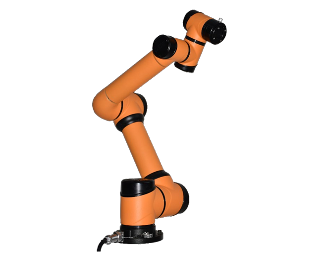
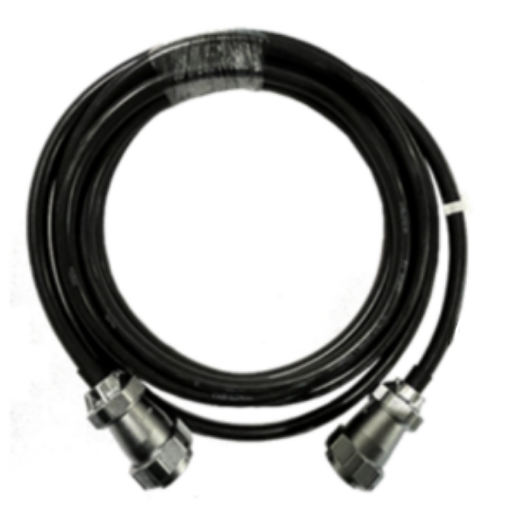
AUBO-CB-C control box is the control center of the robot, containing the control mainboard, safety interface board, switching power supply, safety protection components, etc. The control box can be powered by 220V AC. Its internal switching power supply converts 220V AC into 24V and 48V DC to power the payloads and the robot inside the box. External connected components include the power cable, wireless handheld tablet, handheld device, robot arm cable, and robot arm. Before use, it is necessary to check whether the connections of the robot, teach pendant, and control box are secure.
The control box is designed with both hardware and software protection to ensure maximum safety during use. The control box uses circuit breakers internally to provide reliable short-circuit protection and overload protection, ensuring the safety of personnel and equipment.
6.2 Safety Instructions
| Sign | Description |
|---|---|
| 1. There are dangerous voltages of 220V AC and 48V DC inside the box. Non-professionals must not open the box while it is powered on. 2. Do not touch the screws or other metal components inside the control box with bare hands, and avoid disassembling connections with power on. 3. Before use, check whether the power cable of the control box is properly connected. 4. Before use, check whether the control box is properly connected to the robot. 5. Before use, check whether the control box is securely supported, level, and stable. 6. The robotic system only supports upgrade and use of the default software. Installation of other software, such as the ROS, is prohibited. If there is a need to install other software, it is recommended that users use other platforms for installation. |
6.3 Control Box Panel
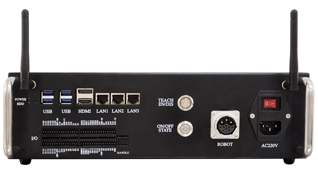
6.3.1 Control Box Front Panel
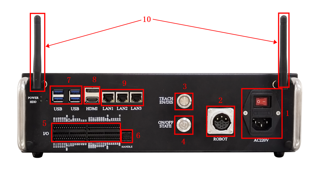
The structure of the control box front panel is shown in the figure below:
| No. | Name | Function |
|---|---|---|
| 1 | AC220V POWER INTERFACE & SWITCH | Power button, where "I" represents on, and "O" represents off. |
| 2 | ROBOT INTERFACE | Robot body cable interface, used for connecting the robot body cable. |
| 3 | TEACH EN/DIS BUTTON & INDICATOR LIGHT | When the wired teach pendant is not in use, pressing this button will turn on the circular indicator light above it. Otherwise, an emergency stop error may occur upon power-on. |
| 4 | ON/OFF STATE BUTTON & TRI-COLOR INDICATOR LIGHT (RED, GREEN, YELLOW) | Power button: After the equipment is powered on and the tri-color indicator light lights up in yellow, press and hold the button for 2 s to start up the equipment. When the equipment is started up, press and hold the button for 2 s to force it to shut down. Tri-color indicator light: An illuminating red light indicates an alarm or warning, an illuminating green light indicates running status, and an illuminating yellow light indicates standby status. |
| 5 | I/O | Safety I/O interface and user I/O interface |
| 6 | HANDLE HANDHELD DEVICE INTERFACE | Insert the jumper cap when the handheld device is not in use. |
| 7 | USB INTERFACE (IPC) | Used for connecting USB devices |
| 8 | HDMI & DP (IPC) | High-definition multimedia interface, used to connect a monitor |
| 9 | LAN1/LAN2/LAN3 (IPC) | Ethernet port |
| 10 | WIFI ANTENNA (IPC) | Wireless connection for wireless handheld tablet |
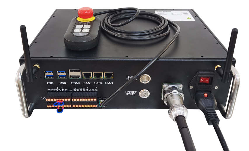
6.4 Cable Connection
Connect robot cable to control box: First, unscrew the dust cap of the ROBOT interface on the control box, and then plug the robot cable connector into the ROBOT interface, as shown in Figure 6-3.
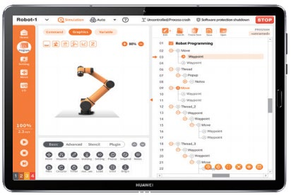
Use the wireless handheld tablet to network the teach pendant to the control box as shown in Figure 6-3.
Connect power cable to control box: Plug the power cable connector into the POWER interface, as shown in Figure 6-3.
6.5 Power On
Place the control box in an appropriate position;
Conduct control box cable connection as described above;
Check whether all cables of the control box are properly connected (teach pendant, terminal block, robot arm cable, etc.);
Connect the power cable and set the power button to "1" position. Then the POWER indicator light will stay red;
Press and hold the ON/OFF STATE button for 2 s and release it. Then the indicator light will flash green. After successful startup, the indicator light will stay green, allowing normal control of the robot arm power-on and operation. During the power-on of the robot arm, the indicator light will flash blue quickly, and after successful power-on, the ON/OFF STATE button indicator light will stay blue.
6.6 Power Off
Press and hold the ON/OFF STATE button for 2 s to disconnect the signal, and the control box will execute the shutdown (shutdown is prohibited during robot operation);
Wait for the blue indicator light of the ON/OFF STATE button to go out;
Set the control box power button to "0" position. Then the red POWER indicator light will go out.
| Sign | Description |
|---|---|
| 1. Shutting down the system by simply unplugging the power cable from the socket may damage the robot file system, leading to robot function failure. 2. The power button on the control handle can be used to power on or off the control box. |
7 Electrical Interface
7.1 Electrical Warnings and Cautions
When designing and installing the robot and AUBO-CB-C control box applications, be sure to follow the following warnings and cautions. These warnings and cautions also apply to maintenance work.
| Sign | Description |
|---|---|
| 1. Never connect safety signals to a non-safety PLC that does not meet the required safety level. Failure to follow this warning may result in serious injury or even death due to the failure of a safeguard stop function. 2. The control box must be powered off during wiring of the electrical interface. 3. Make sure that all non-waterproof equipment remains dry. If water enters the product, please disconnect the power supply and contact your supplier. 4. Use original cables supplied with the robot only. Do not use the robot for applications where the cables will be bent. Contact your supplier if longer or flexible cables are needed. 5. All GND connections mentioned in this document are only for power supply and signal transmission. For Protective Earth (PE), use the screw connections marked with the earth symbols inside the control box. The grounding conductor shall have at least the current rating of the highest current in the system. 6. When wiring the robot control box I/O, make sure the power is off. 7. Interference signals higher than the level specified in the IEC standard will cause the abnormal behavior of the robot. Extremely high signal levels or excessive exposure can cause permanent damage to the robot. EMC problems typically occur in welding process and are usually indicated by error messages in the log. AUBO (Beijing) Intelligent Technology Co., Ltd. is not liable for any losses caused by EMC problems. 8. I/O cables used to connect the control box to another machinery and factory equipment may not be longer than 30 m, unless extended tests are performed. |
7.2 I/O Power Supply
For example, in the case of NPN, if an external power supply is required, please follow the wiring method below:
| Sign | Description |
|---|---|
| The internal power supply is only for low-power devices. |
7.3 Safety I/O of Control Box
7.3.1 Introduction
Safety devices and equipment must be installed according to the safety instructions and can only be used after a comprehensive risk assessment is conducted. Safety I/O is located on the terminal block inside the control box.
| Sign | Description |
|---|---|
| Every safety I/O is of NPN type by default during delivery. |
7.3.2 Safety Instructions
| Sign | Description |
|---|---|
| 1. Never connect safety signals to a non-safety PLC that does not meet the required safety level. 2. Be sure to separate safety interface signals from regular I/O signals. 3. Before using the robot, be sure to check the safety features, which must be tested regularly. |
7.3.3 Safety I/O Function Definition
| I/O type | I/O name | Function definition | |
| Fixed I/O | EI1 | EI0 | External Emergency Stop |
| Configurable I/O | CI00~CI05 | CI10~CI15 | Emergency Stop Reduced Mode Safeguard Stop Safeguard Reset 3-Position Switch Operational Mode HandGuide Auto Mode Safeguard Stop Auto Mode Safeguard Reset |
| CO00~CO05 | CO10~CO15 | System Emergency Stop System Not Emergency Stop Robot Moving Robot Not Moving Reduced Mode Not Reduced Mode Robot Not Stopping Safe Home | |
- CI00~CI05, CI10~CI15, CO00~CO05, CO10~CO15 can only be used as safety I/O after being configured in the software. If not configured, it will be used as general digital I/O of the control box. For specific usage, please refer to the software manual.
Fixed safeguard stop input:
- Linkage emergency stop input: used for emergency stop devices only, enabling synchronized emergency stops across multiple machines.
The difference between external emergency stop input and safeguard stop input is as follows:
| LinkAGE Emergency Stop | |
|---|---|
| Robot Stop Moving | Yes |
| Program Execution | Stop |
| Robot Power Supply | Off |
| Reset | Manual |
| Operating Frequency | Infrequent |
| Need for Reinitialization | Yes |
| Shutdown Category | 1 |
| Safety input function | Limit case | ||
| Detection time | Power-off time | Response time | |
| Linkage Emergency Stop | 100ms | 1200ms | 1300ms |
7.3.4 NPN Type I/O
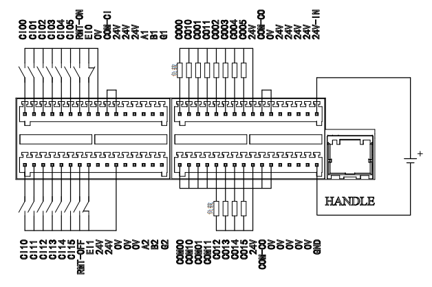
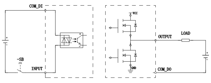
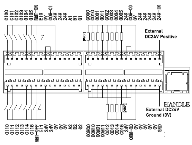
When the controller I/O interfaces use NPN transistors, "logic high" means the output is in the "on" state, with voltage close to ground voltage (such as 0V), and "logic low" means the output is in the "off" state, without output voltage. COM_CI common input terminals and COM_CO common output terminals are wired as follows.
When COM-CI is connected to 24V and Cixx is connected to 0V, the input is valid;
When COM00 is connected to 0 V, CO00 outputs 24V, which is valid;
When COM01 is connected to 0 V, CO10 outputs 24V, which is valid;
When COM02 is connected to 0V, CO01 outputs 24V, which is valid;
When COM03 is connected to 0V, CO11 outputs 24V, which is valid;
When COM-CO is connected to 0V, CO02-CO05, and CO12-CO15 output 24V, which is valid.
The NPN type connection method for the I/O module of the control box is shown in the figure below.
| Sign | Description |
|---|---|
| 1. COM00, COM10, COM01, and COM11 are independent COM terminals, corresponding to output points CO00, CO10, CO01H, and CO11 respectively. 2. The source type (PNP) and sink type (NPN) I/O may be connected freely according to requirements, independent of other COM terminals. |
7.3.5 PNP Type I/O
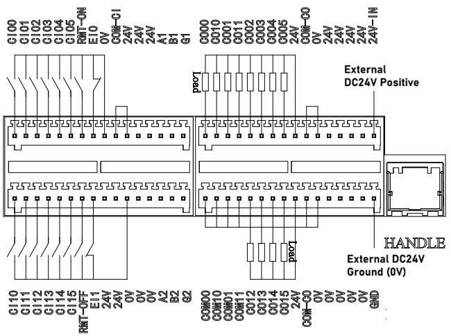
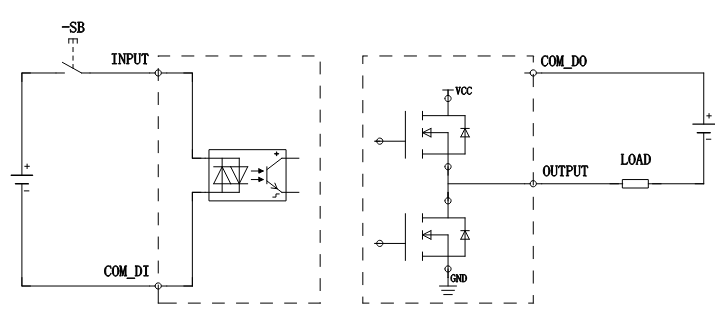
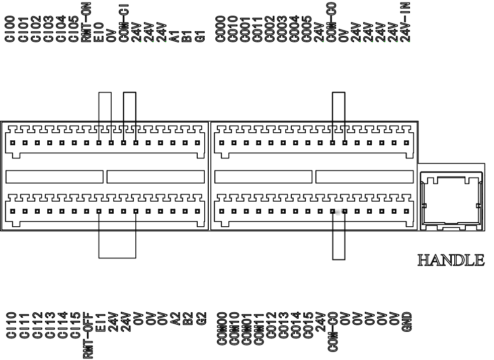
When the controller I/O interfaces use PNP transistors, "logic high" means the output is in the "on" state, with voltage close to supply voltage (such as 24V), and "logic low" means the output is in the "off" state, without output voltage. COM_CI common input terminals and COM_CO common output terminals are wired as follows.
When COM-CI is connected to 0V and CIxx is connected to 24V, the input is valid;
When COM00 is connected to 24V, CO00 outputs 0V, which is valid;
When COM01 is connected to 24V, CO10 outputs 0V, which is valid;
When COM02 is connected to 24V, CO01 outputs 0V, which is valid;
When COM03 is connected to 24V, CO11 outputs 0V, which is valid;
When COM-CO is connected to 24 V, CO02-CO05, and CO12-CO15 output 0 V, which is valid.
The PNP type connection method for the I/O module of the control box is shown in the figure below.
| Sign | Description |
|---|---|
| 1. COM00, COM10, COM01, and COM11 are independent COM terminals, corresponding to output points CO00, CO10, CO01H, and CO11 respectively. 2. The source type (PNP) and sink type (NPN) I/O may be connected freely according to requirements, independent of other COM terminals. |
7.3.6 Default Safety Configuration
The robot is delivered with default safety configuration, as shown in the figure below. Therefore, the robot can be used safely without additional safety devices. NPN is taken as an example here (PNP is the default safety configuration, and the level signals are opposite).
7.3.7 Configurable I/O
After the corresponding functions are configured in the software, the defined functions can be realized through the I/O connections on the control box. The input signal is connected to the CI terminal on the control box, and the output signal is connected to the CO terminal on the control box. The other end needs to be connected according to the NPN/PNP definition selected for the control box. For example:
After the software is configured for a safeguard stop (e.g., CI00/CI10), safeguard stop devices can be connected through this interface.
After the software is configured for robot moving (e.g., CO01), valid level signals can be sent through this interface when the robot's host computer is running.
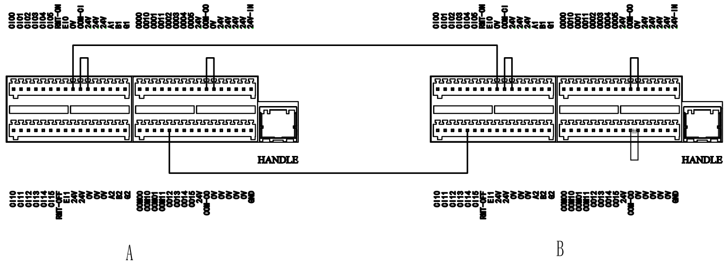
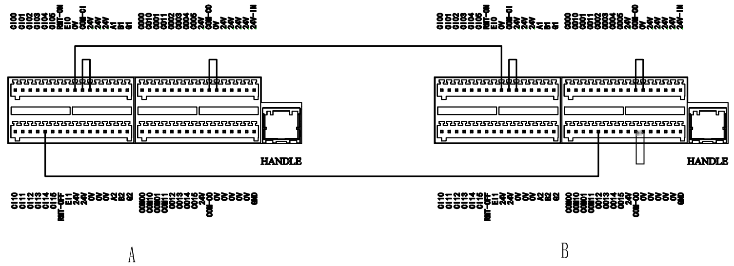
7.3.8 Shared Emergency Stop Input
Users can control the robot to enter a Category 1 stop state by receiving external stop signal input after configuration and connection of relevant interfaces. This input may be used in multi-robot collaboration mode to share the emergency stop circuit with other robots by setting a common emergency stop line. Operators may use the emergency stop button on any robot to bring all robots on the line to an emergency stop status.
Users may refer to the following example, where the controller software of control box A and control box B is both configured for the system not in emergency stop (e.g., CO00). The two robots can share the emergency stop circuit through NPN or PNP type connection, as shown in Figure 7-7, enabling emergency stop of two robots after either of them sends an emergency stop signal. The following is an example of NPN type connection.
7.4 General I/O of Control Box
The internal terminal panel of the control box is provided with 16 general digital input interfaces and 12 general digital output interfaces.
| Sign | Description |
|---|---|
| All connected external devices shall have a common ground with the control box. |
7.4.1 General digital I/O Interfaces
There are 16 general digital input terminals in the control box (hereinafter referred to as "CI terminals"), which operate in NPN/PNP mode. For details, please refer to the previous sections.
The CI terminals can be used to read signals from switch buttons, sensors, PLCs, or other AUBO robots.
There are 12 general digital output terminals inside the control box (hereinafter referred to as "CO terminals"), which operate in NPN/PNP mode. For details, please refer to the previous sections.
The CO terminals can be directly connected to payloads or communicate with PLCs or other robots.
Users can control the above digital I/O using the teach pendant software.
| Input | CI00 | CI01 | CI02 | CI03 | CI04 | CI05 | CI10 | CI11 | CI12 | CI13 | CI14 | CI15 | RMT_ON | RMT_OFF | EI0 | EI1 |
|---|---|---|---|---|---|---|---|---|---|---|---|---|---|---|---|---|
| Output | CO00 | CO01 | CO02 | CO03 | CO13 | CO14 | CO04 | CO05 | CO10 | CO11 | CO12 | CO15 | ||||
| CI/CO | Parameter | Specification |
| CI | Input signal form | NPN/PNP |
| Input method | Input signal current | |
| Electrical specifications | 5mA/DC24V | |
| CO | Output form | NPN/PNP |
| Electrical specifications | 300mA/DC24V |
It should be noted that in the I/O, CO00/CO10~CO01/CO11 must correspond to COM00/COM10~COM01/COM11; otherwise, the I/O output will be invalid. The active level mode here can be customized as NPN/PNP.
| I/O Name | Active level mode | COM00~COM11 electrical connection | Electrical connection for external payload |
|---|---|---|---|
| CO00/CO10 CO01/CO11 | NPN | COM00~COM11 connected to 0V respectively | One end of the payload is connected to CO00, and the other end connected to 24V. Similar connection for other user I/O. |
| CO00/CO10 CO01/CO11 | PNP | COM00~COM11 connected to 24V respectively | One end of the payload is connected to CO00, and the other end connected to 0V. Similar connection for other user I/O. |
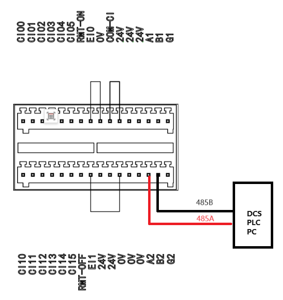
7.4.2 RS485 Interface
The RS485 interface is located on the control box interface board, where there are two RS485 input interfaces, labeled as 485, as shown in the figure below, including A1B1 representing the IPC RS485 interface, and A2B2 representing the extended RS485 interface. This interface may be used for communication of RS485 data streams through the host computer and connection with external devices. This interface supports baud rates from 2400 bps to 115200 bps, which can be modified through the host computer. The setting takes effect immediately (default 115200 bps).
7.5 I/O Interfaces for Remote On/Off Control
The I/O interfaces for remote on/off control are located on the control box interface board.
The I/O interfaces for remote on/off control can be used to turn on or off the robotic system.
| Input | Function description |
|---|---|
| RMT-ON | Remote startup signal input interface |
| RMT-OFF | Remote shutdown signal input interface |
| Sign | Description |
|---|---|
| COM_CI and COM_CO are in NPN mode by default. Please pay attention to the specific input/output level. |
8 Use of Control Handle
8.1 Introduction
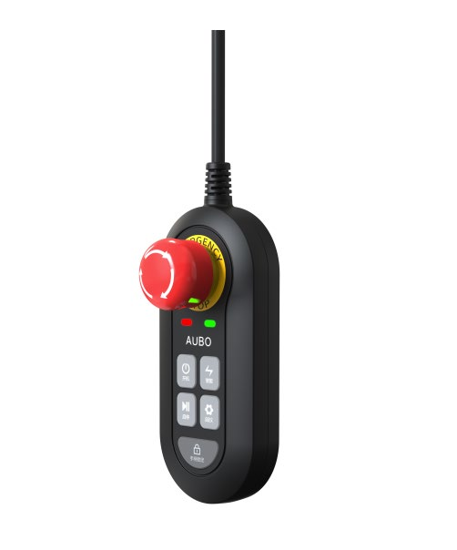
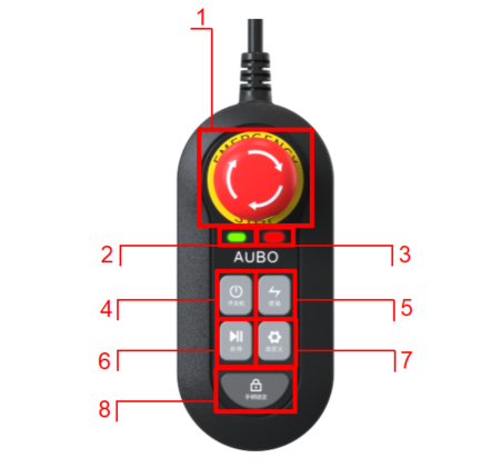
The control handle allows for quick operations on the robotic system. In the AUBO STUDIO teach pendant software, the function to turn on/off the control handle can be configured, and the control handle is turned on by default during delivery. A magnet is placed on the back of the control handle for easy attachment. Its structure is shown in Figure 8-1. For the function description of each button/indicator light, see Table 8-1.
| No. | Name | Function |
|---|---|---|
| 1 | Emergency Stop button | Press the Emergency Stop button to enable emergency stop of the robot. To restore the normal mode, rotate this button as arrowed. |
| 2 | Power indicator light | It indicates the control box power status: Off: Control box is powered off. Flashing: Control box is powered on, and robot arm is powered off. Constantly on: Control box and robot arm are powered on. |
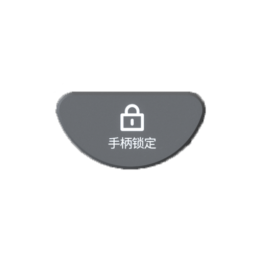
| 3 | Lock indicator light | It indicates the handle lock status: On: Handle is locked, and button operations are invalid. Off: Handle is unlocked, and button operations are valid. |
| 4 | ON/OFF button | It controls the control box to be powered on/off. |
| 5 | Enable button | It controls the robot arm to be powered on/off and enabled. |
| 6 | Start/Stop button | It is used for start/stop and pause/resume of robot arm program during operation, for quick operation without teach pendant software during operation, and for debugging and inspection during deployment or maintenance. |
| 7 | Custom button | Users can customize the function of this button in the AUBO STUDIO teach pendant software. |
| 8 | Handle locking button | It is used for locking and unlocking the control handle |
8.2 Operation of Control Handle
1. Emergency Stop
Activate emergency stop: In case of an emergency, pressing the Emergency Stop button can immediately stop all movements of the robot to protect the safety of the operator. At this time, the robot is in emergency stop mode.
Deactivate emergency stop: After troubleshooting, rotating the Emergency Stop button as arrowed on the button can exit the emergency stop mode, and the robot can return to normal mode.
2. Power On/Off
Power on control box: Long press the ON/OFF button
 for 2s and then release it. The control box will enter the "boot process". Wait for about 20s, and the power indicator light
  will start flashing, indicating that the control box boot process is completed.
Power off control box: Long press the ON/OFF button
for 2s and then release it. The power indicator light will go out, indicating that the control box power-off is completed.
3. Robot Arm Control
Power on robot arm: When robot arm is powered off, short press the Enable button
 to power on the robot arm. Wait for about 20s, and the power indicator light will change from flashing to constantly on, indicating that the robot arm power-on is completed.
Enable robot arm: When robot arm is powered on but not enabled, short press the Enable button
. The robot arm joints will make click sounds, and the brake system will be released, indicating that the robot enters an operational status.Power off robot arm: When robot arm is powered on, long press the Enable button
for 2s and then release it. The robot arm will be enabled and powered off, and the power indicator light will change from constantly on to flashing, indicating that the power-off is completed.
4. Program Control
Start program: When no program is running (just after power on or after the running program is stopped), long press the Start/Stop button
 for 2s and then release it to start the program; if no default program is set, the robot arm will not perform actions.
Pause/resume program: When a program is running, short press the Start/Stop button
to pause/resume the program.Stop program: When a program is running, long press the Start/Stop button
for 2s and then release it to stop the program (the program cannot be resumed after stop and can only be restarted).
5. Handle Lock/Unlock
Lock handle: When handle is unlocked, long press the handle locking button
 for 2s and then release it. The handle locking indicator light
  will be constantly on, the control handle will be locked, and the buttons cannot be used except for Emergency Stop button.
Unlock handle: When handle is locked, long press the handle locking button
for 2s and then release it. The handle locking indicator light will go out, the control handle will be unlocked, and the buttons can be used again.
6. Custom Function
- Set custom function: Users can set the function of Custom button
 in the teach pendant software.
| Button | Function definition |
| Custom button | Return to Home |
| HandGuide | |
| Record feature points | |
| Track playback |
9 Appendix
9.1 Specifications
| Control box model | AUBO-CB-C | |
| Control box dimensions (Length*Width*Height) | 350mm x 300mm x 100mm | |
| Control box weight | 7.8kg | |
| IP rating | IP 30 | |
| Power supply input | 220VAC, 50-60Hz | |
| I/O port | Digital input | 16 (configurable) |
| Digital output | 12 (configurable) | |
| RS485 | 2 (UT-890A recommended) | |
| I/O power supply | DC 24V 2A max | |
| Operating temperature | 0-50°C | |
| Transportation and storage temperature | -20°C ~ 60°C | |
| Humidity | 90% RH (non-condensing) | |
| Cooling method | Air cooling | |
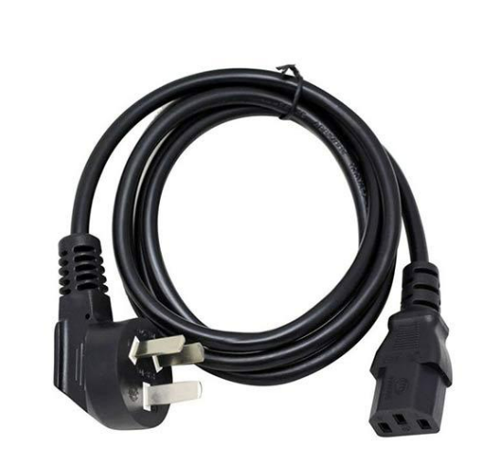
| Cable length | AC power cable | 5m |
| Robot arm cable | 5m | |