AUBO-CB-M Control Box User Manual
1 About this Manual
1.1 Version information
v1.0.2
This User Manual will be regularly reviewed and revised, and updated in the form of a new version. The content or information in this manual is subject to change without prior notice.
AUBO (Beijing) Intelligent Technology Co., Ltd. is not responsible for any errors or omissions that may occur in this manual, or for any incidental or consequential damages arising from the use of this manual and the products described herein.
Please read this manual before installing or using the product.
Please keep this manual in a safe place for easy reading and reference.
All pictures in this manual are for reference only; please refer to the actual product received.
This manual is the exclusive property of AUBO (Beijing) Intelligent Technology Co., Ltd. Without the written permission of AUBO (Beijing) Intelligent Technology Co., Ltd., this manual may not be copied, reproduced in whole or in part, or transformed into any other form of use.
Copyright © 2015-2026 AUBO. All rights reserved.
2 Revision History
| Version No. / Date | Description |
|---|---|
| v1.0.1/20240805 | Release of trial version v0.0.1. |
| v1.0.2/20240827 | Release of trial version 0.0.2. 1. LI03 function was defined as "Return to initial position". 2. Description of I/O quantities was updated in each chapter. |
3 Safety
3.1 Introduction
This chapter introduces the safety principles and specifications to be observed when operating the control box or robotic system. Integrators and users must carefully read this manual, paying special attention to the content marked with warning signs, which must be strictly followed. Due to the complexity and inherent dangers of the robotic system, operators need to fully understand the risks of operation and strictly adhere to and implement the specifications and requirements outlined in this manual. Users and integrators must have a strong safety awareness and abide by the industrial robot safety standard ISO 10218.
3.2 Warning Signs
The content related to safety in this manual is indicated by the following warning signs. The explanations of the warning signs in the manual represent important information and must be strictly followed.
| Sign | Explanation |
|---|---|
 | Imminent dangerous conditions that, if not avoided, could result in death or serious injury. |
 | Potentially dangerous electrical conditions that, if not avoided, could result in injuries to personnel or serious damage to equipment. |
 | Potentially dangerous conditions that, if not avoided, could result in injuries to personnel or serious damage to equipment. Items marked with this symbol may, depending on the specific situation, have the potential for significant consequences. |
 | A condition that, if not avoided, could result in injuries to personnel or damage to equipment. Items marked with this symbol may, depending on the specific situation, have the potential for significant consequences. |
3.3 Safety Precautions
When starting the robot or robotic system for the first time, you should understand and follow the basic information below. Other safety-related information is introduced in other sections of the manual. However, it is also impossible to cover everything. In practical applications, specific issues need to be analyzed on a case-by-case basis.
| Sign | Description |
|---|---|
| 1. Always install the robot and all electrical equipment in accordance with the requirements and specifications in this manual. 2. Carry out preliminary testing and inspection of the robot and its protective system before the first use and production deployment of the robot. 3. Before the initial startup of the system and equipment, be sure to check whether the equipment and system are complete, whether the operation is safe, and whether any damage has been detected. During this inspection, check the compliance with the effective production safety regulations and standards of the country or region, and be sure to test all safety features. 4. Users must verify that all safety parameters and user programs are correct, and that all safety features are functioning properly. All safety features shall be checked by personnel qualified to operate the robot. The robot can only be started after passing comprehensive and careful safety testing and meeting the required safety level. 5. The robot should be installed and debugged by qualified professionals in accordance with the installation standards. 6. After the robot installation and construction, a comprehensive risk assessment must be conducted again and documented. 7. The safety parameters shall be set and altered by authorized personnel, and passwords or isolation measures shall be applied to prevent unauthorized personnel from altering or setting the safety parameters. After the safety factor is modified, the relevant safety features need to be analyzed. 8. In the event of an accident or abnormal operation, press the emergency stop switch to stop the robot. |
| 1. The control box generates heat during operation. Therefore, do not operate or touch the robot while it is working or immediately after it has stopped. 2. Cut off the power supply and wait for 1 h for the robot to cool down. 3. Never insert your fingers into the heated area of the control box. |
| 1. Ensure that the machine is correctly and safely installed. 2. Ensure the robot's arms have enough space to move freely. 3. Do not connect safety devices to regular I/O interfaces; connect them to safety interfaces only. 4. Ensure that the correct installation settings are made. 5. Connecting different machines may increase hazards or induce new hazards. Always conduct a thorough risk assessment of the entire installation. When different safety and emergency stop performance levels are required, always choose the highest level. Always read and understand the manuals for all equipment used in the installation. 6. Never modify the robot. Modifications to the robot may cause hazards that the integrator cannot foresee. The authorized reconfiguration of the robot should comply with the latest versions of all relevant service manuals. AUBO (Beijing) Intelligent Technology Co., Ltd. disclaims any responsibility for the robot that has been modified or altered in any way. 7. Before transporting the robot, users need to check the insulation and protective measures. 8. During handling of the robot, the transportation requirements must be followed. Handle the robot with care to avoid collisions. |
| 1. When the machine is connected to the machinery that can cause damage to the machine or is working alongside, it is strongly recommended to check all functions of the machine separately. 2. AUBO (Beijing) Intelligent Technology Co., Ltd. is not responsible for any damage to the robot or personal injuries caused by improper operation of the robot. 3. Do not expose the robot to a permanent magnetic field, as high-intensity magnetic fields can damage the robot. |
3.4 Responsibilities and Regulations
AUBO-CB-M control box can be integrated with other devices to form a complete machine, but they are not complete by themselves. Therefore, this manual does not include how to comprehensively design, install, and operate a complete robot, nor does it cover all the potential impacts on the safety of the peripheral equipment of this complete system. The safety of a complete robot installation depends on how the robot is integrated. Integrators should abide by the national laws, regulations, and safety standards to conduct a risk assessment for the design and installation of this complete system. Risk assessment is one of the most important tasks that integrators must complete, and they can refer to the following standards to conduct the risk assessment.
ISO 12100:2010 Safety of Machinery - General Principles for Design - Risk Assessment and Risk Reduction;
ISO 10218-2:2025 Robots and Robotic Devices - Safety Requirements for Industrial Robots - Part 2: Robot Systems and Integration;
RIA TR R15.306-2014 Technical Report for Industrial Robots and Robot Systems - Safety Requirements - Task-Based Risk Assessment Methodology;
ANSI B11.0-2010 Safety of Machinery - General Requirements and Risk Assessment.
The responsibilities to be fulfilled by an integrator include but are not limited to:
comprehensive risk assessment of complete robot system;
confirmation of the correctness of the system's design and installation;
provision of training to users and staff;
development of the operation specification of the complete system with specific operation process defined;
development of appropriate safety measures;
adoption of appropriate methods to eliminate hazards or minimize any hazards to an acceptable level at the time of final installation;
communication of residual risks to end users;
marking of the integrator's logo and contact information on the robot;
archiving of relevant technical documents.
For applicable standards and laws, please visit: www.aubo-robotics.cn.
All safety-related information contained in this manual should not be regarded as a guarantee by AUBO (Beijing) Intelligent Technology Co., Ltd. Even with adherence to all safety instructions, injuries to personnel or damage to equipment may still occur.
AUBO (Beijing) Intelligent Technology Co., Ltd. is committed to continuously improving the reliability and performance of its products and reserves the right to upgrade products without prior notice. AUBO (Beijing) Intelligent Technology Co., Ltd. strives to ensure the accuracy and reliability of the content in this manual but is not responsible for any errors or omissions herein.
3.5 Intended Use
AUBO-CB-M control box is limited to general industrial equipment use and is only allowed to be used under specified environmental conditions. For specific information regarding operating environment and conditions, please refer to the appendix.
AUBO-CB-M control box has special safety level characteristics and is limited to general industrial equipment use. Unintended uses must be avoided. Prohibited uses include, but are not limited to, the following situations:
Use in hazardous environments such as flammable or explosive areas;
Use in devices that move or handle people or other animals;
Use in devices related to medical equipment that involves human life;
Use in devices that have a significant impact on society and the public;
Use in vehicles, ships, and other environments subject to vibration;
Use as climbing tools.
3.6 Emergency Handling
For recovery from an emergency, all button-type emergency stop devices have a "lock" function. This "lock" must be opened to end the emergency stop state.
| Sign | Description |
|---|---|
| Recovery from the emergency stop state is a simple yet crucial step, which can only be performed after ensuring that all hazards of the robotic system have been completely eliminated. |
4 Handling and Precautions
Before transportation, the robot should be packaged according to packaging standards, and marked with required signs on the outside of the package.
During transportation, the robot should be stable and remain fixed in the appropriate position.
The control box should be lifted by the handle. During hoisting and transportation, appropriate measures should be taken to secure the moving parts to prevent any unexpected movement which can cause damage.
Move the robot from the packaging material to the installation position. After securing, power on the robot and check whether it operates normally.
Keep the original packaging after transportation. Store the packaging material in a dry place for future repackaging and handling of the robot.
| Sign | Description |
|---|---|
| Ensure that your back or other body parts are not excessively strained when lifting the machine. All regional and national guidelines must be followed. AUBO (Beijing) Intelligent Technology Co., Ltd. is not liable for any damage incurred during the transportation of the equipment. Ensure strict adherence to the installation instructions in the manual when installing the robot. |
5 Maintenance and Disposal
5.1 Maintenance
Maintenance work must be carried out strictly according to all safety instructions in this manual.
Maintenance must be carried out by authorized system integrators or AUBO (Beijing) Intelligent Technology Co., Ltd. Parts to be returned to AUBO (Beijing) Intelligent Technology Co., Ltd. must be handled according to the service manual.
It is essential to ensure the specified safety level for maintenance work, comply with effective national or regional work safety regulations, and test whether all safety features are functioning properly.
The purpose of maintenance work is to ensure the system operates normally or to help restore normal conditions in the event of a system failure. Maintenance work includes fault diagnosis and maintenance.
| Sign | Description |
|---|---|
| 1. Remove the main input cable from the back of the control box to ensure it is completely powered off. Take necessary precautions to prevent others from re-energizing the system during maintenance. After the power is turned off, be sure to check that the system is powered off. 2. Please check the ground connection before turning on the system again. 3. Observe the ESD (Electrostatic Discharge) regulations when disassembling the robot arm or control box. 4. Avoid disassembling the power supply system of the control box. High voltages can be present inside the power supply system for several hours after the control box has been switched off. 5. Avoid water or dust entering the control box. |
| 1. Replace the defective components with new components with the same part number or equivalent components approved by AUBO (Beijing) Intelligent Technology Co., Ltd. 2. Reactivate all disabled safety measures immediately after the work is completed. 3. Document all maintenance operations in writing and include them in the technical documentation for the entire robotic system. 4. The control box does not include any parts that can be repaired by the end users themselves. If maintenance services are needed, please contact your dealer or AUBO (Beijing) Intelligent Technology Co., Ltd. |
5.2 Disposal
The AUBO-CB-M control box must be disposed of in accordance with applicable national laws, regulations, and standards.
6 Warranty
6.1 Product Warranty
The AUBO-CB-M robot comes with a limited warranty period of 18 months.
If new equipment and its components exhibit defects due to manufacturing or material issues within 18 months of being put into use, AUBO (Beijing) Intelligent Technology Co., Ltd. shall provide necessary spare parts for replacement or repair of related components.
AUBO (Beijing) Intelligent Technology Co., Ltd. shall have the ownership of the equipment or components which have been replaced or returned to AUBO (Beijing) Intelligent Technology Co., Ltd.
If the product is no longer under warranty, AUBO (Beijing) Intelligent Technology Co., Ltd. shall reserve the right to charge the customer for replacement or repair costs.
If any defects appear in the equipment outside the warranty period, AUBO (Beijing) Intelligent Technology Co., Ltd. shall not be liable for any damages or losses arising therefrom, such as production losses or damage to other production equipment.
6.2 Disclaimer
If the equipment defect is caused by improper handling or failure to follow the instructions in the User Manual, the product warranty shall be void.
Failures caused by the following conditions are not covered by this warranty:
Products purchased from non-AUBO approved channels;
Installation, wiring, or connection to other control devices that does not comply with industrial standards or the requirements of the User Manual;
Use beyond the product specifications or standards;
Use for purposes other than those specified;
Service conditions that exceed the nominal specifications of the product;
Use in a grinding environment or under special service conditions without proper protection;
Damage to the product caused by improper transportation;
Failures, damages, or consequential damages caused by accidents or human factors;
Failures, damages, or consequential damages caused by modifications;
Installation of non-genuine parts or accessories;
Damage caused by modifications, debugging, or maintenance of original parts by third parties other than AUBO (Beijing) Intelligent Technology Co., Ltd. or the designated integrator;
Failures, damages, or consequential damages caused by natural disasters or other acts of force majeure;
Failures caused by reasons other than those mentioned above and not related to the responsibility of AUBO (Beijing) Intelligent Technology Co., Ltd.
The following situations are not covered by the warranty:
Failure to identify product traceability number.
Failure to identify production date or warranty start date.
Changes to software or internal data.
Fault cannot be reproduced or cannot be identified by AUBO (Beijing) Intelligent Technology Co., Ltd.
Use of the product in radioactive equipment, biological testing equipment, or other applications deemed hazardous by AUBO (Beijing) Intelligent Technology Co., Ltd.
Exterior parts and vulnerable parts.
According to the product warranty agreement, AUBO (Beijing) Intelligent Technology Co., Ltd. only provides warranty for flaws and defects in products and parts sold to dealers.
AUBO (Beijing) Intelligent Technology Co., Ltd. does not assume any other express or implied warranties or liabilities, including but not limited to, any implied warranties of merchantability or fitness for a particular purpose. In addition, AUBO (Beijing) Intelligent Technology Co., Ltd. is not liable for any form of consequential damages or consequences arising from the relevant products.
7 Control Box
7.1 Introduction
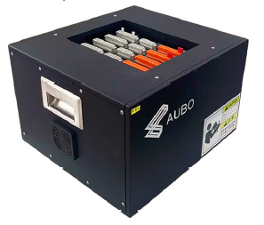
The control box is the control center of the AUBO robot, consisting of control mainboard, safety interface board, switching power supply, safety protection components, etc. The control box adopts 100V-240V AC power supply. Its internal switching power supply can convert 100V-240V AC into 12V, 24V, and 48V DC so as to supply power to the payloads and the robot in the control box. Before use, it is necessary to check whether the connections of the robot, teach pendant, and control box are secure.
The control box is designed with both hardware and software protection to ensure maximum safety during use. The control box uses multiple circuit breakers internally, providing reliable short-circuit protection and overload protection. An emergency stop switch can also be externally connected to the control box, allowing users to cut off the robot's power supply in the shortest time to protect personnel and equipment safety.
7.2 Important Safety Instructions
| Sign | Description |
|---|---|
| The robotic system only supports upgrade and use of the default software. Installation of other software, such as the ROS, is prohibited. If there is a need to install other software, it is recommended that users use other platforms for installation. |
| Precautions before use: 1. Check whether the power supply connector of the control box is properly connected. 2. Check whether the control box is properly connected to the robot. 3. Check whether the control box is properly connected to the teach pendant. 4. Check whether the control box is securely supported, level, and stable. 5. There are dangerous voltages of 100V-240V AC and 48V DC inside the box. Non-professionals must not open the box while it is powered on. |
| Do not touch the screws or other metal components inside the control box with bare hands, and avoid disassembling connections with power on. |
7.3 Control Box Panel
7.3.1 Control Box Front Panel
The structure of the control box front panel is shown in the figure below.
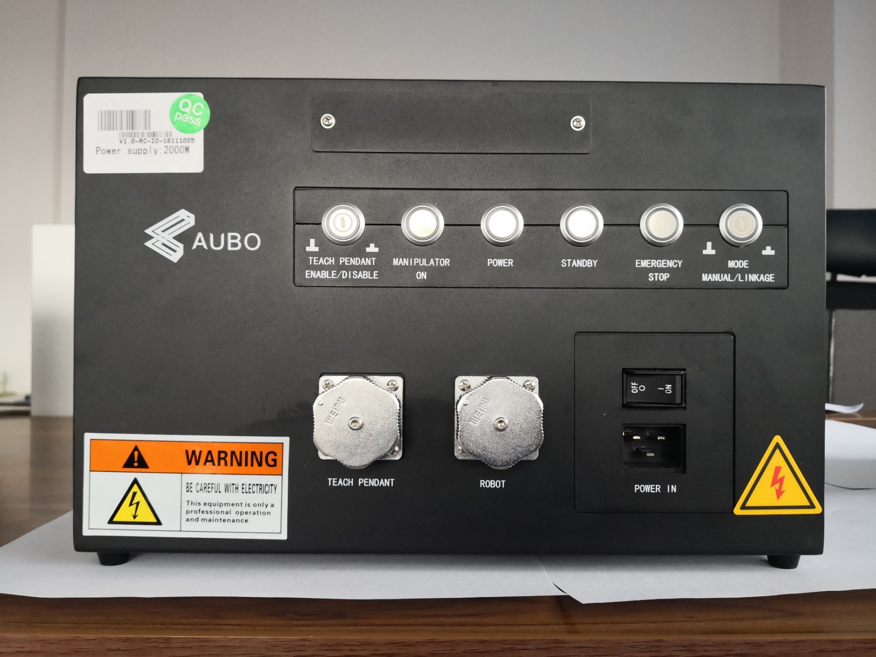
| Name | Function |
|---|---|
| TEACH PENDANT ENABLE/DISABLE | TEACH PENDANT ENABLE/DISABLE button |
| MANIPULATOR ON | The indicator light comes on to indicate that the robot is powered on. |
| POWER | The indicator light comes on to indicate that the external power is on. |
| STANDBY | The indicator light comes on to indicate that the control box interface board program is initialized and the robot can be powered on by pressing the teach pendant power button. The indicator light flashes to indicate that the control box is powered on and waiting for connection. |
| EMERGENCY STOP | The indicator light comes on to indicate that the robot is in emergency stop status. |
| MODE MANUAL/LINKAGE | Not available. |
| TEACH PENDANT | Teach pendant cable interface, used for connecting the teach pendant cable. |
| ROBOT | Robot arm cable interface, used for connecting the robot arm cable. |
| POWER IN | Power switch and power cable interface. |
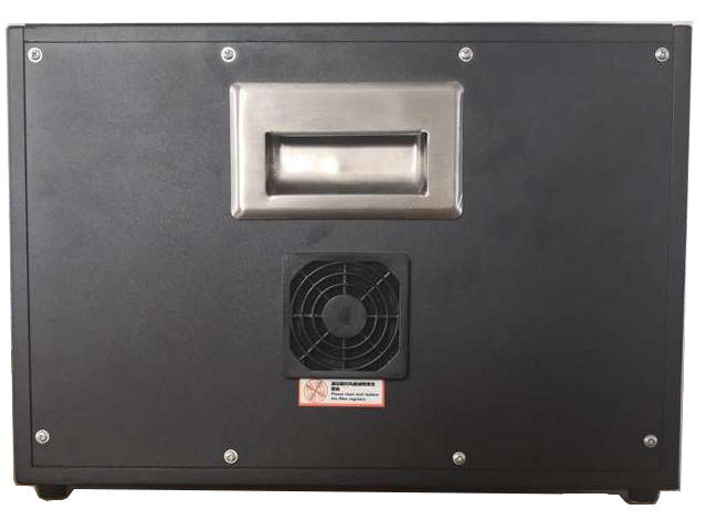
7.3.2 Control Box Side Panel
The sides of the control box provide fans.
7.3.3 Control Box Top Panel
The top of the control box provides Ethernet interface and USB interface, as shown in the figure below.
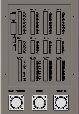
| No. | Interface | Function |
|---|---|---|
| 1 | Ethernet interface | It can be used for remote access and control. |
| 2 | Modbus RTU interface | It can be connected to Modbus devices |
| 3 | USB interface | It can be used to update software and import/export project files. |
| 4 | External electrical interface of control box | External I/O interface |
| Sign | Description |
|---|---|
| Do not plug or unplug USB devices during the operation of the robot arm. |
7.4 TEACH PENDANT ENABLE/DISABLE button
The TEACH PENDANT ENABLE/DISABLE button is used when the teach pendant is not required. Normally, this button pops up and the teach pendant can be used normally (the teach pendant emergency stop function is available). If you need to unplug the teach pendant, press this button; at this time, the teach pendant emergency stop function is not available, and you can unplug the teach pendant cable, and use interface signals to control the robot status.
The TEACH PENDANT ENABLE/DISABLE button is located on the upper left side of the control box panel, as shown in the figure below:

| Sign | Description |
|---|---|
| The TEACH PENDANT ENABLE/DISABLE button must be turned on or off with the control box powered off. An external Emergency Stop button is required. |
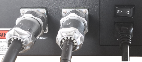
7.5 Cable Connection
Connect robot arm cable to control box: First, unscrew the dust cap of the ROBOT interface on the control box front panel, and then plug the robot cable connector into the ROBOT interface, as shown in Figure 7-7.
Connect teach pendant cable to control box: Plug the teach pendant cable connector into the TEACH PENDANT interface on the control box, as shown in Figure 7-7.
Connect power cable to control box: Plug the power cable connector into POWER IN, as shown in Figure 7-7.
Connect control handle to control box (optional): Plug the control handle cable connector into the handle adapter plate, and then connect the handle adapter plate to the control box. For specific wiring methods, please refer to Section 8.7.
7.6 Power On
Place the control box in an appropriate position;
Conduct control box cable connection as described above;
Check whether all cables of the control box are properly connected (teach pendant cable, power cable, robot arm cable, terminal block, etc.);
Plug the power cable, turn on the power switch, the POWER indicator light on the control box front panel lights up, and wait for the STANDBY indicator light to come on;
Long press the ON/OFF button on the wired teach pendant until you enter the system, and then you can normally power on and operate the robot arm.
7.7 Power Off
There are several methods for normal power-off:
Method 1: Click the [OFF] button on the teach pendant software interface, wait for the STANDBY indicator light to come on, then turn off the power switch, and unplug the power cable.
Method 2: Long press the ON/OFF button on the wired teach pendant, wait for the STANDBY indicator light to come on, then turn off the power switch, and unplug the power cable.
Method 3: Long press the ON/OFF button on the control handle, wait for the STANDBY indicator light to come on, then turn off the power switch, and unplug the power cable.
Forced power-off:
Method 1: Long press the ON/OFF button on the wired teach pendant for 10s.
Method 2: Long press the ON/OFF button on the control handle for 10s.
Method 3: Simply unplug the power cable or turn off the power switch.
| Sign | Description |
|---|---|
| Simply unplugging the power cable from the socket or turning off the power switch may damage the robot file system, leading to robot function failure. |
8 Electrical Interface
8.1 Electrical Warnings and Cautions
When designing and installing the robot and AUBO-CB-M control box applications, be sure to follow the following warnings and cautions. These warnings and cautions also apply to maintenance work.
| Sign | Description |
|---|---|
| 1. Never connect safety signals to a non-safety PLC that does not meet the required safety level. Failure to follow this warning may result in serious injury or even death due to the failure of a safeguard stop function. 2. The control box must be powered off during wiring of the electrical interface. 3. All safety signals have dual-circuit safety channels (redundant design). Keeping the two channels independent can ensure no loss of safety features in the event of a single failure. |
| 1. Make sure that all non-waterproof equipment remains dry. If water enters the product, please disconnect the power supply and contact your supplier. 2. Use original cables supplied with the robot only. Do not use the robot for applications where the cables will be bent. Contact your supplier if longer or flexible cables are needed. 3. All GND connections mentioned in this document are only for power supply and signal transmission. For Protective Earth (PE), use the screw connections marked with the earth symbols inside the control box. The grounding conductor shall have at least the current rating of the highest current in the system. 4. Be careful when installing the interface cable to the robot I/O. |
| 1. Interference signals higher than the level specified in the IEC standard will cause the abnormal behavior of the robot. Extremely high signal levels or excessive exposure can cause permanent damage to the robot. EMC problems typically occur in welding process and are usually indicated by error messages in the log. AUBO (Beijing) Intelligent Technology Co., Ltd. is not liable for any losses caused by EMC problems. 2. I/O cables used to connect the control box to another machinery and factory equipment may not be longer than 30 m, unless extended tests are performed. |
8.2 Control Box Communication Interface
AUBO-CB-M control box provides various electrical interfaces for connecting external devices, bringing convenience to users.
After removing the protective cover of the control box top panel, you can see Ethernet interface, Modbus RTU interface, USB interface, and some electrical interfaces. (See 7.3.3 Control box top panel)
Ethernet interface
The Ethernet interface can be used for remote access and control.
Modbus device interface
The Modbus device interface is located on the control box top panel (see 7.3.3 Control box top panel). The Modbus devices can be connected via USB interface and Modbus RTU interface.
The pins of the Modbus RTU interface are shown in the figure below:
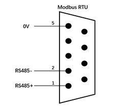
USB interface
The USB interface is located on the control box top panel (see 7.3.3 Control box top panel), and can be used to connect devices, upgrade software and export project files.
8.3 Control Box I/O Power Supply
8.3.1 Internal Power Supply
The control box panel I/O defaults to the internal power supply mode, as shown in the figure below:
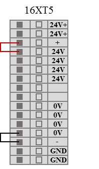
8.3.2 External Power Supply
If the user needs to use an external power supply, please follow the wiring method below.
| Sign | Description |
|---|---|
| The control box must be powered off during wiring of the electrical interface. |
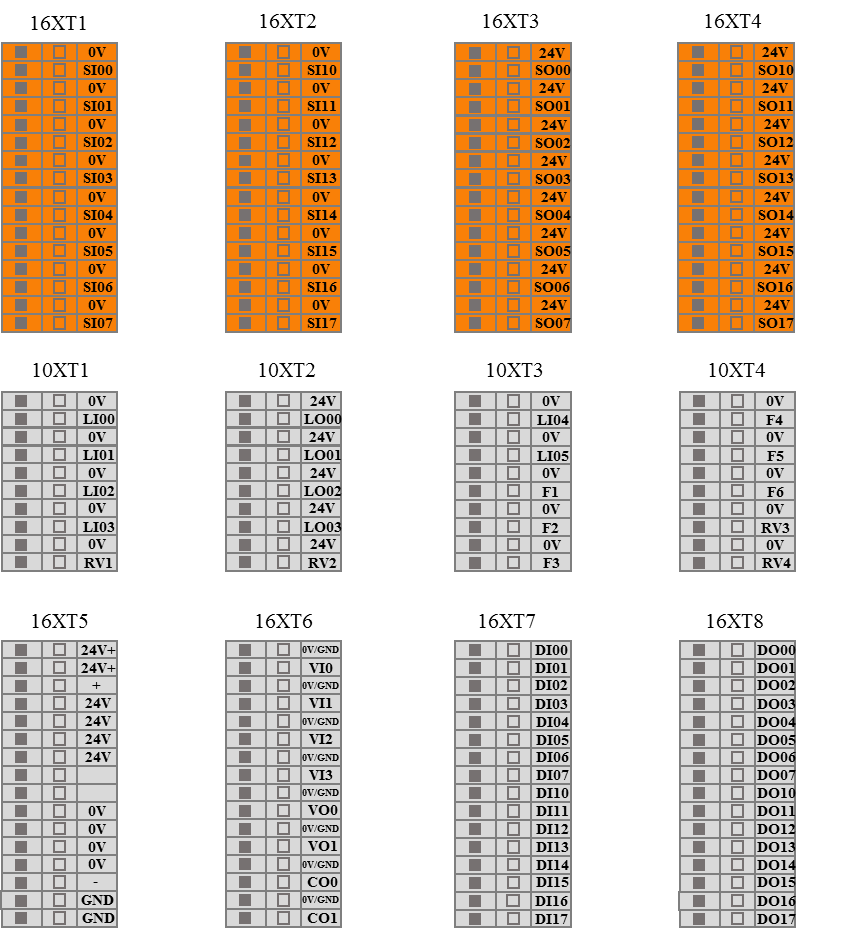
8.4 Fixed I/O of Control Box
AUBO-CB-M control box provides 6 fixed DI interfaces and 4 fixed DO interfaces. For specific fixed function descriptions, please refer to the Software User Manual.
| Input | Interface type | Function definition |
|---|---|---|
| LI00 | NPN | Start program |
| LI01 | NPN | Stop program |
| LI02 | NPN | Pause program |
| LI03 | NPN | Return to initial position |
| LI04 | NPN | Remote power on |
| LI05 | NPN | Remote power off |
| Output | Interface type | Function definition |
|---|---|---|
| LO00 | NPN | Logic low after program stop. In linkage mode, when the program execution is completed or terminated, logic low will be set. |
| LO01 | NPN | Logic high after program stop. In linkage mode, when the program execution is completed or terminated, logic high will be set. |
| LO02 | NPN | Program paused. In linkage mode, when the program is paused, logic high will be set. |
| LO03 | NPN | Function 1: Home. In linkage mode, when the robot arm joint's spatial position reaches the home, logic high will be set. Function 2: Handle function - green indicator light. Note: Function 1 is set by default. After the handle control function is activated, it switches to Function 2. |
8.5 Configurable I/O of Control Box
AUBO-CB-M control box provides 16 configurable DI interfaces and 16 configurable DO interfaces. The configurable I/O has dual-loop safety channels to ensure no loss of safety features in the event of a single failure. Safety devices and equipment must be installed according to the safety instructions and can only be used after a comprehensive risk assessment is conducted.
The configurable I/O can only be used as safety I/O after being configured in the teach pendant software; if not configured, it will be used as general digital I/O of the control box. Safety I/O has a higher priority than general I/O, meaning that when the same I/O is configured as both safety I/O and general I/O, only the function of safety I/O is retained. The specific functions and descriptions of safety I/O can be referenced in the Software User Manual.
| I/O | Interface type | Function definition |
|---|---|---|
| SI00-SI07 | NPN | Specific functions can be set via software interface |
| SI10-SI17 | NPN | |
| SO00-SO07 | NPN | Specific functions can be set via software interface |
| SO10-SO17 | NPN |
8.6 General I/O of Control Box
AUBO-CB-M control box provides 4 general analog input interfaces, 2 general analog voltage output interfaces, 2 general analog current output interfaces, 16 general DI interfaces, and 16 general DO interfaces. The functions of general I/O need to be configured in the teach pendant software, and the specific functions and descriptions can be referenced in the Software User Manual.
| I/O | Interface type | Function definition |
|---|---|---|
| VI0-VI3 | NPN | Specific functions can be set via software interface |
| VO0-VO1 | NPN | |
| CO0-CO1 | NPN | |
| DI00-DI07 | NPN | Specific functions can be set via software interface |
| DI10-DI17 | NPN | |
| DO00-DO07 | NPN | |
| DO10-DO17 | NPN |
8.7 Control Handle I/O
AUBO-CB-M control box reserves 6 digital interfaces to connect the control handle. To connect the control handle, first connect a handle adapter plate connected to the control box, and then connect the handle adapter plate to the control handle.
8.7.1 Function Definition of Control Box Reserved I/O
| I/O | Interface type | Function definition |
|---|---|---|
| F1 | NPN | Handle function - ON/OFF button |
| F2 | NPN | Handle function - Enable button |
| F3 | NPN | Handle function - Start/Stop button |
| F4 | NPN | Handle function - Custom button |
| F5 | NPN | Handle function - Emergency Stop button |
| LO03 | NPN | Handle function - Green indicator light (valid only when control handle function is enabled) |
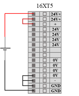
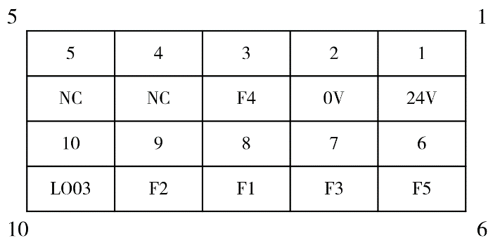
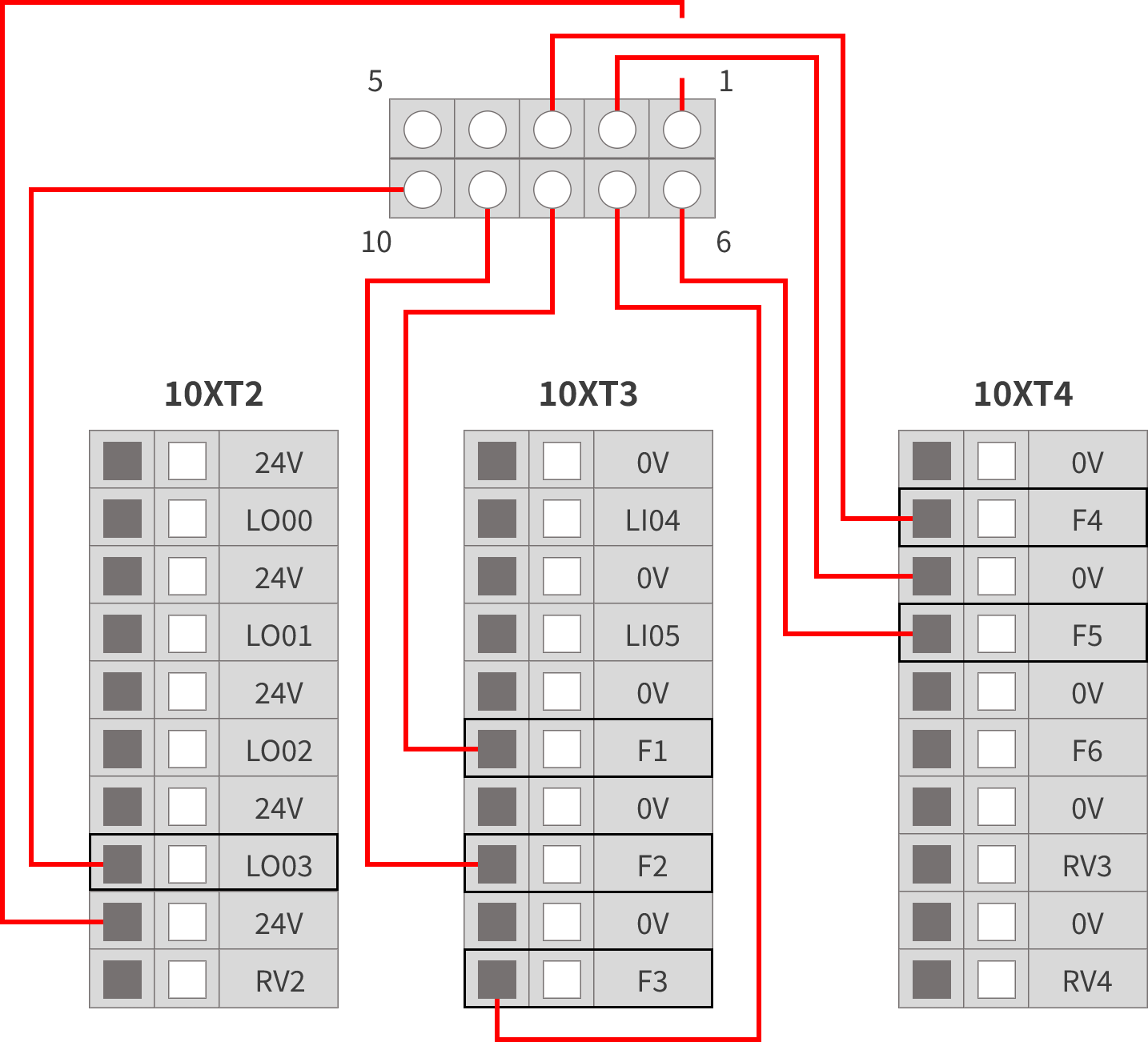
8.7.2 Connection of Handle Adapter Plate
A handle adapter plate must be used to connect the AUBO-CB-M control box and the control handle. The pins and the wiring of the control handle adapter plate are shown in the figures below.
9 Appendix
9.1 Specifications
| Control box type | AUBO-CB-M | |
| IP rating | IP20 | |
| Control box dimensions (Length*Height*Width) | 380mm*350mm*265mm | |
| Control box weight | 15kg | |
| I/O port | Digital input | 32 |
| Digital output | 32 | |
| Analog input | 4 | |
| Analog output | 4 | |
| I/O power supply | DC24V 3A | |
| Communication protocol | Ethernet, ModBus-RTU/TCP, Profinet (optional) | |
| Interface and openness | SDK (supporting C/C++/C#/Lua/Python development), ROS, API | |
| Operating temperature | Robot operating temperature range: 0-50°C | |
| Transportation and storage temperature | -25°C ~ 55°C | |
| Humidity | 90% RH (non-condensing) | |
| Power supply | 100-240 VAC, 50-60 Hz | |
| Connecting cable | Cable connecting robot arm and control box (5m) Cable connecting teach pendant and control box (4m) Cable connecting power supply and control box (5m) | |
9.2 Stop Method
| Stop method | Stop operation |
|---|---|
| Type 0 stop | Robot arm power off |
| Type 1 stop | Robot arm decelerated to 0 - braked - powered off |
| Type 2 stop | Robot arm decelerated to 0 |
| Type 3 stop | Robot arm braked and powered off |