AUBO-iS Series Robot Arm User Manual
1 About this Manual
Version information
v1.0.2
The User Manual will be regularly checked and corrected, and the updates will be incorporated in the new version. The information in this manual is subject to change without notice.
AUBO (Beijing) Intelligent Technology Co., Ltd. shall not be liable for any errors or omissions in this Manual, or for any accidental or consequential injuries arising from the use of this Manual and the products described therein.
Please read this manual before installing and using the product described herein.
Please keep this manual for the convenience of reading or reference when necessary.
All pictures in this manual are for reference only and the product received serves as the standard.
This Manual is the exclusive property of AUBO (Beijing) Intelligent Technology Co., Ltd. and may not be copied, reproduced in whole or in part, or converted into any other form for use without the written permission of AUBO (Beijing) Intelligent Technology Co., Ltd.
Copyright © 2015-2026 AUBO All rights reserved.
This publication is the User Manual of AUBO-iS robot arm, and applies to the following products: AUBO-iS3, AUBO-iS7, AUBO-iS10, AUBO-iS20, AUBO-iS20L, AUBO-iS25 and AUBO-iS35.
Use of this Manual
This Manual is applicable to the installation, commissioning, maintenance, repair and disassembly of AUBO-iS series robot arm.
Intended readers
This Manual is intended for the following professionals:
- Installation personnel;
- Maintenance personnel;
- Repair personnel.
Preconditions for operation
Readers are required to have the following basic knowledge and qualifications:
- Professional training experience by AUBO;
- Knowledge about installation, maintenance and repair of mechanical and electronic devices;
- Basic awareness of safe operation.
Associated documents
- AUBO-CB-iS Series Controller User Manual
- AuboStudio User Manual
Additional information
For more information, please visit our official website at: www.aubo-robotics.cn
2 Revision
| Version / Time | Description |
|---|---|
| v1.0.1*/20251013 | v1.0.1* (Trial) released. |
3 Safety
3.1 Warning Signs
Safety-related instructions in this Manual are highlighted by the following warning signs. Instructions following those warning signs in this manual are very important and must be followed.
| Sign | Description |
|---|---|
 | It indicates a possibly hazardous situation that, if not avoided, could result in death or serious injury. |
 | It indicates a possibly hazardous situation, if not avoided, could result in injury to personnel or major damage to equipment. |
 | It indicates a possibly hazardous situation, if not avoided, could result in injury to personnel or damage to equipment. Attention shall be paid that the hazards indicated by this sign may sometimes cause more significant consequences, depending on the specific circumstances. |
 | It indicates a situation that, if not avoided, could result in injury to personnel or damage to equipment. Attention shall be paid that the hazards indicated by this sign may sometimes cause more significant consequences, depending on the specific circumstances. |
3.2 Safety Precautions
3.2.1 Instructions for Use
The following basic information needs to be understood and followed when the robot is used for the first time. Also, other safety-related information will be introduced in other parts of this manual. However, it may not cover all don'ts and prohibitions due to the presence of so many possibilities.
| Sign | Description |
|---|---|
| 1. Always install the machine and all electrical equipment in accordance with the requirements and specifications herein. 2. Make sure to perform a preliminary test and inspection of the machine and its protection system before using the robot or putting it into production for the first time. 3. Before starting the robot or robot system for the first time, check whether the robot or robot system is in good condition and safe for operation, without any damage detected; and test, with all safety functions covered, whether the currently effective national or local safety production rules and regulations are satisfied. 4. Always check that all safety parameters and user programs are correct and that all safety functions are working properly, which must be done by personnel qualified to operate the robot. Do not start the robot until it has passed the thorough safety test, proving that it reaches the specified safety level. 5. Always get the installation and commissioning performed by professionals according to the installation standards. 6. When the robot is installed, carry out a comprehensive risk assessment again and keep a record therefor. 7. Always get the setting and modification of safety parameters carried out by authorized personnel, and apply security measures such as password or isolation measure to prevent their unauthorized modification or setting. After the safety factor is modified, be sure to analyze the relevant safety functions. 8. In case of an accident or abnormal operation, press down the emergency stop button to stop the robot if necessary. 9. Now that the AUBO-iS series robot arm joint module is equipped with a brake to keep the robot attitude when the power is off, do not power on and power off frequently, and as a recommendation, please keep an interval of more than 10s between each startup and shutdown. 10. The AUBO-iS series robot arm is designed with the collision detection function to stop the robot automatically when the external force on the robot exceeds the normal range set by the user, thereby preventing robot damage or operator injury by collision. Though a function specially designed in the AUBO-iS series robot arm for the safety of human-machine coordination, it also requires that the robot system must be within the normal operating range and the AUBO series controller used. If the self-developed controller is used, this function is unavailable, and the user is required to bear all possible dangerous consequences arising therefrom. 11. Considering that the robot arm generates heat during operation, do not operate or touch the robot when it is working or immediately after it stops. Instead, cut off the power supply and wait for an hour until the robot cools down. 12. Do not put your fingers in the heating part of the controller. |
| 1. Make sure that the robot arm and tools are properly and securely installed in place. 2. Make sure that there is enough space for the robot arm to move freely. 3. Stop using the robot when it is damaged. 4. Do not connect safety devices to general-purpose I/O interfaces, and instead, please use safety-related interfaces only. 5. Make sure to use the correct installation settings (e.g. robot arm installation angle, TCP weight, TCP offset, security configuration). 6. Prevent tools and obstacles that have sharp corners or twist points. Make sure that all people keep their heads and faces outside the reach of the robot. 7. Pay attention to the movement of the robot when the teach pendant software is used. 8. Prevent collisions of any type, as they will release a kinetic energy that is much higher than that in the case of operation at high speed and high payload. 9. Since connection of different machines may increase the risk or lead to new dangers, always perform a comprehensive risk assessment for the entire installation. When different safety and emergency shutdown performance levels are required, always select the highest one. Always read and understand the manuals of all equipment used in the installation. 10. Do not modify the robot, as any changes to the robot may cause unpredictable danger to the integrator. Carry out robot restructuring with authorization and according to the latest version of all relevant service manuals. If the robot is changed or altered in any way, AUBO (Beijing) Intelligent Technology Co., Ltd. disclaims all liability. 11. Before transporting the robot, check the insulation and protection measures. 12. Follow the transportation requirements when transporting the robot, and handle it carefully to avoid bumps. |
| 1. When the robot is combined with or working together with other machine that can cause robot damage, it is strongly recommended to check all functions of the robot separately. 2. AUBO (Beijing) Intelligent Technology Co., Ltd. shall not be liable for any robot damage or personal injury caused by improper operation. 3. Do not expose the robot to a permanent magnetic field, as strong magnetic fields can damage the robot. |
3.2.2 Operator Safety
Operator safety is the first consideration that must be secured during the operation of the robot system. The general precautions are listed in the table below, and appropriate measures shall be taken to ensure the safety of operators.
| Sign | Description |
|---|---|
| 1. Each operator using the robot system shall be trained through the training courses hosted by AUBO (Beijing) Intelligent Technology Co., Ltd. Users shall fully grasp the safe and standardized operating procedures with the robot operating qualifications. Please inquire for training details via email support@aubo-robotics.cn. 2. Do not wear loose clothes or jewelry when working with the robot systems, and make sure long hairs are combed up at the back of the head. 3. When the robot is running, even if it appears to have stopped, it is possible that the robot is waiting for a start signal and in the state of imminent action, and even in such state, the robot should be considered as being in motion. 4. In emergency and abnormal situations, for example, when an operator is caught in or surrounded by a robot, push or pull the robot arm with force to force the joint to move. Manual movement of the robot arm without electric drive is for emergency use only, and may cause damage to the robot arm joint. |
3.3 Responsibilities and Regulations
The AUBO-CB-iS series controller can be combined with other equipment to form a complete machine and itself is not complete. Therefore, this Manual does not cover the instructions on how to design, install and operate a complete robot, nor does it cover all peripheral equipment that can influence the safety of the complete system. The safety of a complete robot installation depends on its integration. The integrator shall conduct risk assessment on the design and installation of the complete system in accordance with laws, regulations, safety codes and standards where the robot is installed. Risk assessment is one of the most important tasks that an integrator must be done. Guidance on the risk assessment process may be found in the following standards.
ISO 12100:2010 Safety of Machinery - General Principles for Design - Risk Assessment and Risk Reduction;
ISO 10218-2:2025 Robots and Robotic Devices - Safety Requirements for Industrial Robots - Part 2: Robot Systems and Integration;
RIA TR R15.306-2014 Technical Report - Industrial Robots and Robot Systems - Safety Requirements - Task-based Risk Assessment Methodology;
ANSI B11.0-2010 Safety of Machinery; General Requirements and Risk Assessment.
The responsibilities to be fulfilled by an integrator include but are not limited to:
comprehensive risk assessment of complete robot system;
confirmation of the correctness of the system's design and installation;
provision of training to users and staff;
development of the operation specification of the complete system with specific operation process defined;
development of appropriate safety measures;
adoption of appropriate methods to eliminate hazards or minimize any hazards to an acceptable level at the time of final installation;
communication of residual risks to end users;
marking of the integrator's logo and contact information on the robot;
archiving of relevant technical documents. For applicable standards and laws, please visit: www.aubo-robotics.cn.
All safety information contained herein shall not be regarded as a guarantee from AUBO (Beijing) Intelligent Technology Co., Ltd. It should be understood that, even if all safety instructions referred to herein are observed, personal injury or equipment damage is still likely to occur.
AUBO (Beijing) Intelligent Technology Co., Ltd. is committed to continuously improving the reliability and performance of its products, and therefore reserves the right to upgrade products without notice. AUBO (Beijing) Intelligent Technology Co., Ltd. will make every possible effort to ensure the accuracy and reliability of the information in this manual, but shall not be liable for any errors or omissions therein.
3.4 Hazard Identification
The risk assessment shall cover all potential contacts between the operator and the robot during normal use and foreseeable misoperation. The neck, face and head of the operator shall not be exposed to avoid contact. When the robot is to be used without peripheral safety means, a risk assessment is required to determine whether the associated hazards constitute an unacceptable risk, for example.
- possible risks from the use of sharp end effectors or tool connectors;
- possible hazards in handling toxic or other hazardous substances;
- risk of the operator's fingers being caught by the robot carriage or joint;
- danger of being hit by robot;
- danger from improper fixing of robot or end-effector;
- danger caused by impact between the robot payload and a solid surface. The integrator must measure such hazards and their associated risk levels through a risk assessment, and determine and implement appropriate measures to reduce the risk to an acceptable level. However, the integrator shall be aware of that specific robot equipment may involve other major hazards for specific robot equipment.
By combining the inherent safety design measures applied by the AUBO with the safety regulations or risk assessment implemented by the integrator and the end user, the risks associated with the collaborative operation of the AUBO-iS series robot arm are reduced to a reasonably practicable level, and then by this manual, any residual risks associated with the robot will be communicated to the integrator and end user prior to installation. If the risk assessment shows that there are hazards in its specific application that may pose an unacceptable risk to users, the integrator must take appropriate risk reduction measures to eliminate these hazards or minimize them to an acceptable level. It is not safe to use the robot until appropriate risk reduction measures have been taken, if required.
In case of non-cooperative installation (for example, when a dangerous tool is used), the risk assessment may infer that the integrator shall connect additional safety means (e.g., safety start-up device) during programming to ensure the safety of personnel and equipment.
3.5 Emergency Response
3.5.1 Emergency Stop Device
Pressing the emergency stop button will immediately stop all motions of the robot. Emergency stop is not intended as a risk reduction measure, but as a secondary protection device. When multiple emergency stop buttons are to be connected, they must be included in the risk assessment of robot application.
All emergency stop devices designed in the form of a button feature a "lock", which must be unlocked to end the emergency stop state.
The robot arm body itself has no emergency stop device in the form of a button, but the controller, wired teach pendant, control handle and other control devices have. For details, please refer to the user manual of the controller or accessories.
| Sign | Description |
|---|---|
| 1. Tooling or equipment connected to the end of the robot must be integrated into the emergency stop circuit of the system if they pose a potential threat. Failure to comply with this warning may result in death, serious personal injury or major property damage. 2. Recovering from the emergency stop state is a simple but very important step, which can be operated only when the danger of the robot system is confirmed to be completely eliminated. |
3.5.2 Emergency Moving of Joint
When necessary, the robot joint can be moved forcibly by:
HandGuide: push or pull the robot arm with force to force the joint to move.
| Sign | Description |
|---|---|
| Forced manual movement of the robot arm is for emergency use only, and may cause damage to the robot arm joint. |
3.5.3 Overload Protection
The robot arm is designed with the overload protection function. When the robot arm is hit by operators or other objects accidentally with the robot arm powered on and stationary, and the collision force exceeds the safety threshold, the robot arm will move passively in the direction of the collision force. This function is intended to reduce injury to personnel, and damage to other objects and robot arm when the operators or other objects collide with the robot arm.
| Sign | Description |
|---|---|
| If it is to be used for other purposes than those described herein, a risk assessment is required. |
3.5.4 Collision Protection
The robot arm is designed with the collision protection function. When operators or other objects accidentally touch the robot arm when the robot arm is operating, and the collision force exceeds the safety threshold, the Category 2 stop will be initiated and the HandGuide mode will be enabled, allowing the operator to drag the robot arm to a relatively safe position and resume the operation of the robot arm by operating the teach pendant. This function can reduce injury to personnel, and damage to other objects and robot arm when the operator or other objects collide with the robot arm, and meanwhile, save the time of restarting the program and improve work efficiency. The safety threshold of the collision force can be changed by setting the collision level.
4 Description of Robot Arms
4.1 AUBO-iS Series
The AUBO-iS series robot arm is an intelligent lightweight 6-DOF modular collaborative robot developed by AUBO (Beijing) Intelligent Technology Co., Ltd. It is available in seven variants, with payload ranging from 3kg to 35 kg and working radius ranging from 0.8865 m to 2.10 m. 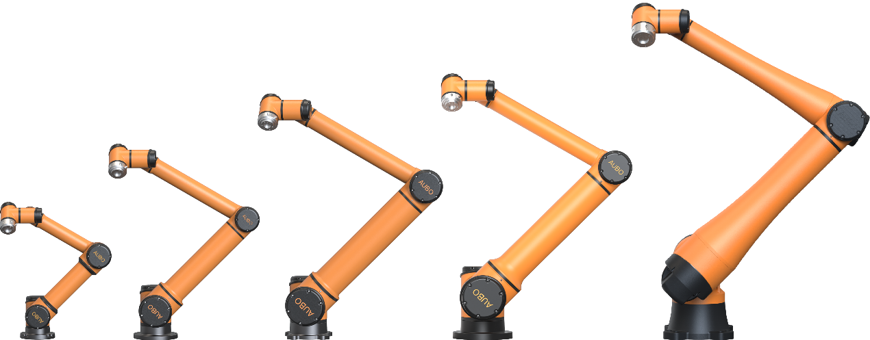
| Sign | Description |
|---|---|
| The AUBO-iS series robot arm (except AUBO-iS35) is compatible with AUBO-CB-iS and AUBO-CB-iS(CE) controllers, and the AUBO-iS35 is only compatible with AUBO-CB-iS-H controller. |
The AUBO-iS series robot arm imitates the human arm and is designed with a total of 6 rotating joints, with each joint representing a DOF. As shown in Figure 4-2, robot arm joints include a base joint (joint 1), a shoulder joint (joint 2), an elbow joint (joint 3), a wrist joint 1 (joint 4), a wrist joint 2 (joint 5), and a wrist joint 3 (joint 6). The base is used for connecting the robot arm body and the carriage, and the tool end is used for connecting the robot arm and the tool. Arm tubes are used for connection of the elbow with the shoulder and the wrist. Through the teach pendant software interface or HandGuide, the user can control the rotation of each joint to move the robot end-effector to different positions. 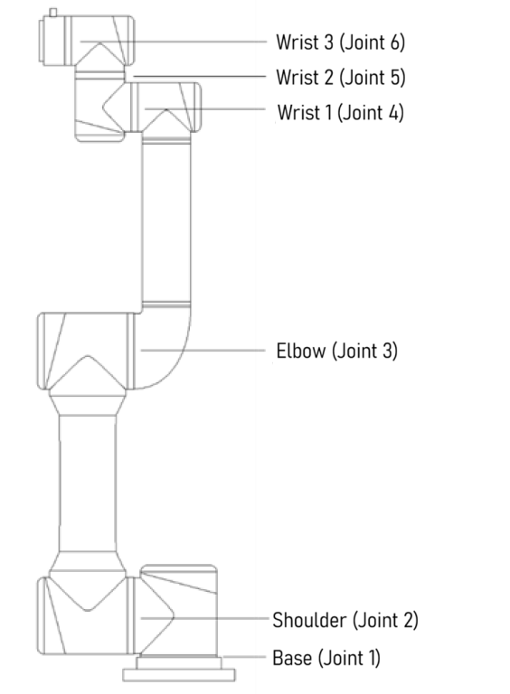
4.2 Technical Specifications
4.2.1 AUBO-iS3
| Robot Arm Type | AUBO-iS3 |
|---|---|
| Degrees of freedom | 6 |
| Weight | 16kg |
| Payload | 3kg |
| Maximum working radius | 625mm |
| Joint range | joint1/joint2/joint4/joint5/joint6: -360° ~ +360° joint3: -156° ~ +156° |
| Maximum joint speed | joint1/joint2/joint3/joint4/joint5/joint6: 237°/s |
| Tool speed | ≤ 2.5m/s |
| Repeatability | ± 0.02mm |
| Ambient temperature | 0 ~ 50°C |
| Ambient humidity | 90% RH (non-condensing) |
| IP rating | IP67 |
| Average power | Approx. 150W when running typical programs |
| Peak power | 1000 W |
| Mounting surface diameter | ⌀140 mm |
| General approval mark/agency | CE |
4.2.2 AUBO-iS7
| Robot Arm Type | AUBO-iS7 |
|---|---|
| Degrees of freedom | 6 |
| Weight | 21.5 kg |
| Payload | 7 kg |
| Maximum working radius | 886.5 mm |
| Joint range | joint1/joint2/joint4/joint5/joint6: -360° ~ +360° joint3: -162° ~ +162° |
| Maximum joint speed | joint1/joint2/joint3: 237°/s joint4/joint5/joint6: 296°/s |
| Tool speed | ≤ 3.6 m/s |
| Repeatability | ± 0.02 mm |
| Ambient temperature | 0 ~ 50°C |
| Ambient humidity | 90% RH (non-condensing) |
| IP rating | IP67 (up to IP68) |
| Average power | Approx. 200W when running typical programs |
| Peak power | 2000 W |
| Mounting surface diameter | ⌀170 mm |
| General approval mark/agency | CE, CR, REACH |
4.2.3 AUBO-iS10
| Robot Arm Type | AUBO-iS10 |
|---|---|
| Degrees of freedom | 6 |
| Weight | 36 kg |
| Payload | 12 kg |
| Maximum working radius | 1300 mm |
| Joint range | joint1/joint2/joint4/joint5/joint6: -360° ~ +360° joint3: -167° ~ +167° |
| Maximum joint speed | joint1/joint2: 178°/s joint3: 237°/s joint4/joint5/joint6: 296°/s |
| Tool speed | ≤ 4.0 m/s |
| Repeatability | ± 0.03 mm |
| Ambient temperature | 0 ~ 50°C |
| Ambient humidity | 90% RH (non-condensing) |
| IP rating | IP67 (up to IP68) |
| Average power | Approx. 500W when running typical programs |
| Peak power | 2000 W |
| Mounting surface diameter | ⌀218 mm |
| General approval mark/agency | CE, CR, REACH |
4.2.4 AUBO-iS20
| Robot Arm Type | AUBO-iS20 |
|---|---|
| Degrees of freedom | 6 |
| Weight | 64 kg |
| Payload | 20 kg |
| Maximum working radius | 1647 mm |
| Joint range | joint1/joint2/joint4/joint5/joint6: -360° ~ +360° joint3: -168° ~ +168° |
| Maximum joint speed | joint1/joint2: 123°/s joint3: 178°/s joint4/joint5/joint6: 296°/s |
| Tool speed | ≤ 3.5 m/s |
| Repeatability | ± 0.05 mm |
| Ambient temperature | 0 ~ 50°C |
| Ambient humidity | 90% RH (non-condensing) |
| IP rating | IP67 (up to IP68) |
| Average power | Approx. 1000W when running typical programs |
| Peak power | 3000 W |
| Mounting surface diameter | ⌀255 mm |
| General approval mark/agency | CE, CR, REACH |
4.2.5 AUBO-iS20L
| Robot Arm Type | AUBO-iS20L |
|---|---|
| Degrees of freedom | 6 |
| Weight | 65 kg |
| Payload | 20 kg |
| Maximum working radius | 2000 mm |
| Joint range | joint1/joint2/joint3/joint4/joint5/joint6: -360° ~ +360° |
| Maximum joint speed | joint1/joint2: 104°/s joint3: 178°/s joint4/joint5/joint6: 296°/s |
| Tool speed | ≤ 3.5 m/s |
| Repeatability | ± 0.05 mm |
| Ambient temperature | 0 ~ 50°C |
| Ambient humidity | 90% RH (non-condensing) |
| IP rating | IP67 |
| Average power | Approx. 1000W when running typical programs |
| Peak power | 3000 W |
| Mounting surface diameter | ⌀282 mm |
| General approval mark/agency | CE, CR, REACH |
4.2.6 AUBO-iS25
| Robot Arm Type | AUBO-iS25 |
|---|---|
| Degrees of freedom | 6 |
| Weight | 73 kg |
| Payload | 25 kg |
| Maximum working radius | 1700 mm |
| Joint range | joint1/joint2/joint3/joint4/joint5/joint6: -360° ~ +360° |
| Maximum joint speed | joint1/joint2: 104°/s joint3: 178°/s joint4/joint5/joint6: 296°/s |
| Tool speed | ≤ 3.0 m/s |
| Repeatability | ± 0.05 mm |
| Ambient temperature | 0 ~ 50°C |
| Ambient humidity | 90% RH (non-condensing) |
| IP rating | IP67 (up to IP68) |
| Average power | Approx. 1000W when running typical programs |
| Peak power | 3000 W |
| Mounting surface diameter | ⌀282 mm |
| General approval mark/agency | CE, CR, REACH |
4.2.7 AUBO-iS35
| Robot Arm Type | AUBO-iS35 |
|---|---|
| Degrees of freedom | 6 |
| Weight | 156 kg |
| Payload | 35 kg |
| Maximum working radius | 2100 mm |
| Joint range | joint1/joint2/joint3/joint4/joint5/joint6: -360° ~ +360° |
| Maximum joint speed | joint1/joint2: 113°/s joint3: 123°/s joint4/joint5/joint6: 237°/s |
| Tool speed | ≤ 4.0 m/s |
| Repeatability | ± 0.05 mm |
| Ambient temperature | 0 ~ 50°C |
| Ambient humidity | 90% RH (non-condensing) |
| IP rating | IP67 |
| Average power | Approx. 1200W when running typical programs |
| Peak power | 6000 W |
| Mounting surface diameter | ⌀423.3 mm |
| General approval mark/agency | CE, CR, REACH |
4.3 Performance Parameters
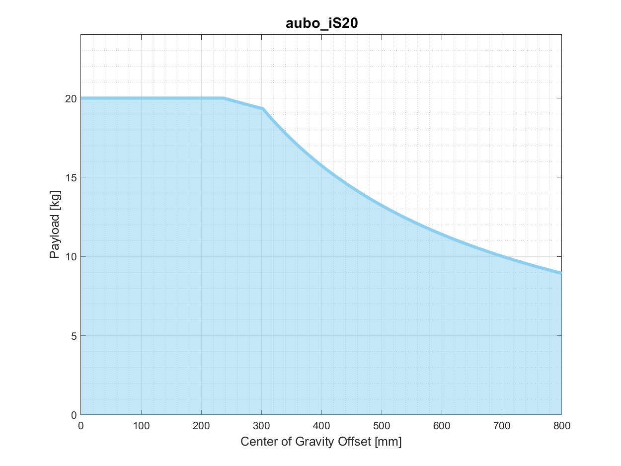
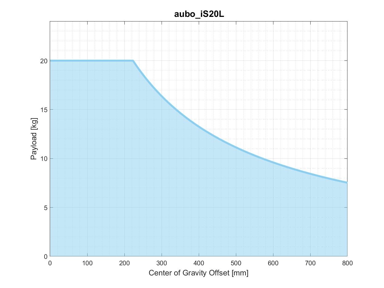
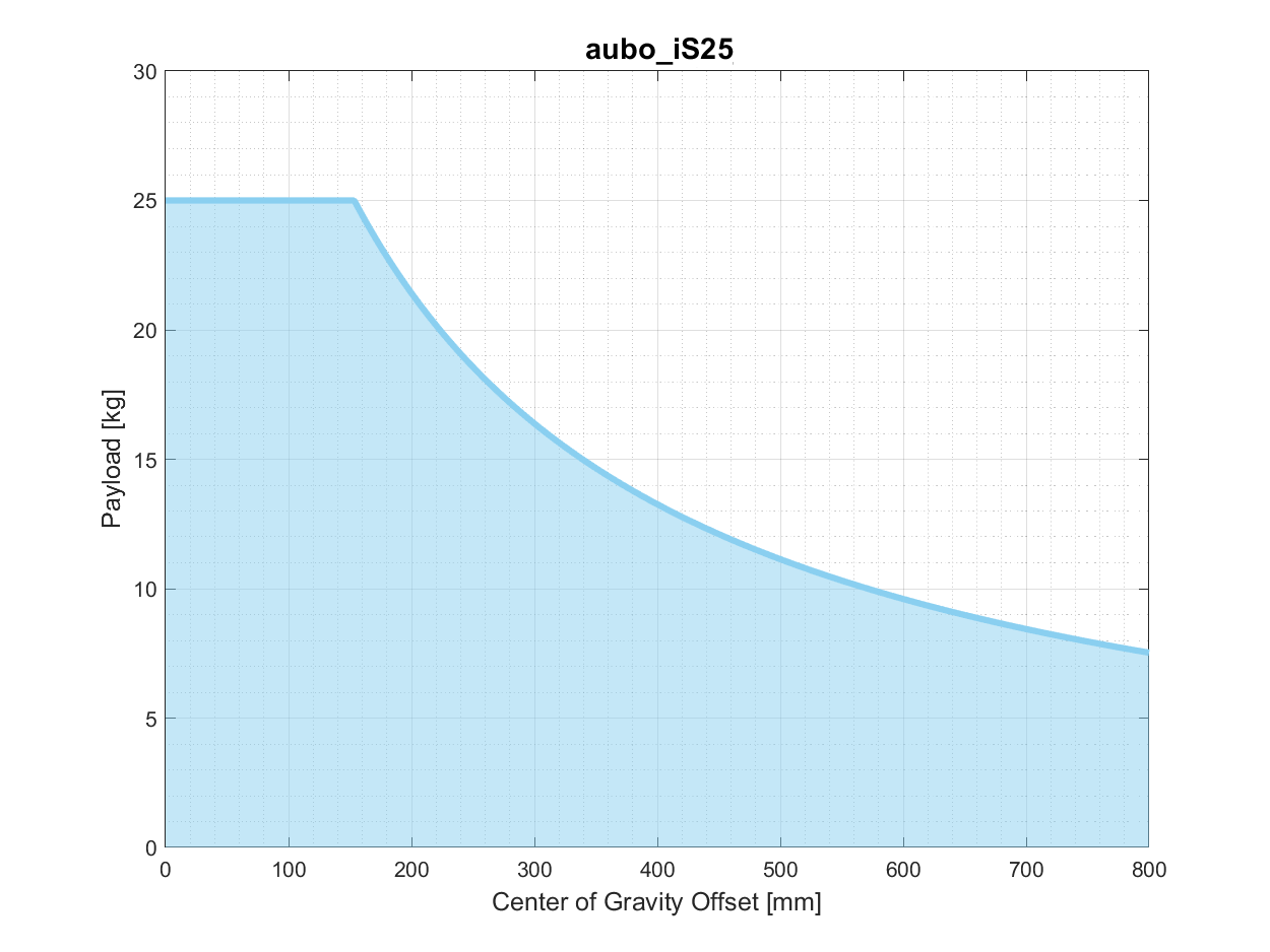
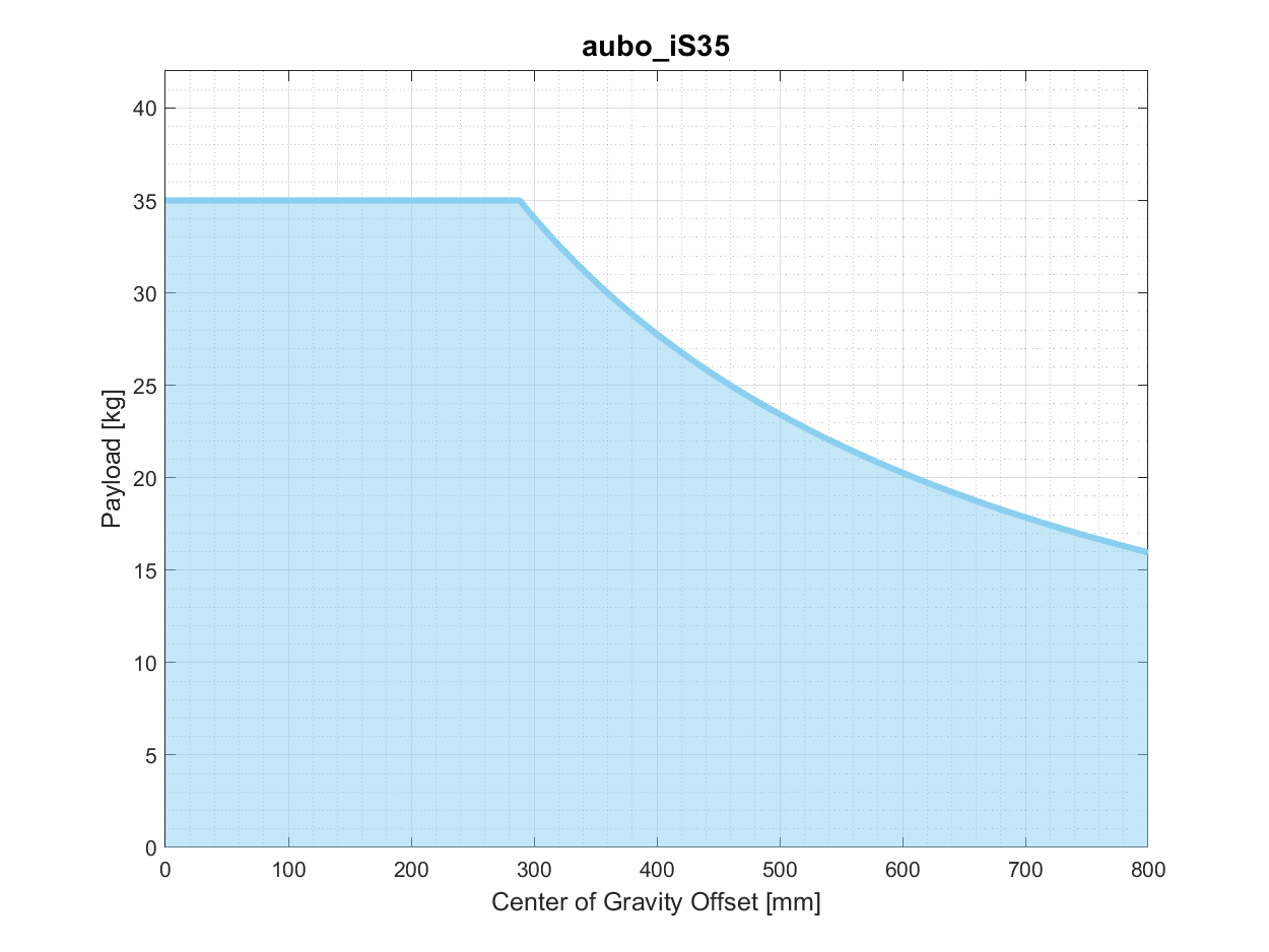
4.3.1 Load Deflection
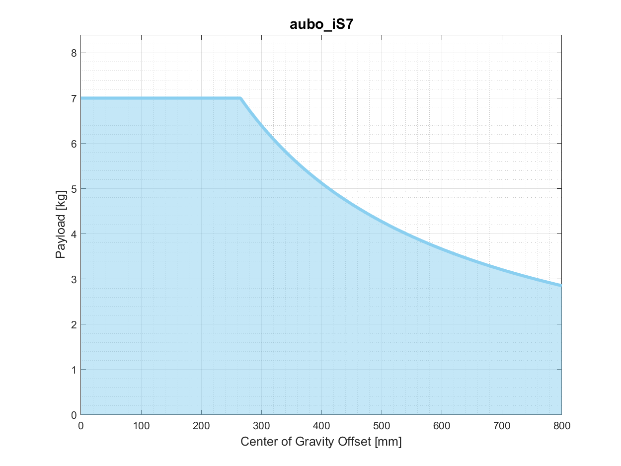
In the following wrist load-deflection curves of the robot arm, the ordinate p represents the payload, and the abscissa d represents the distance from the center of the end effector flange to the center of the tool. 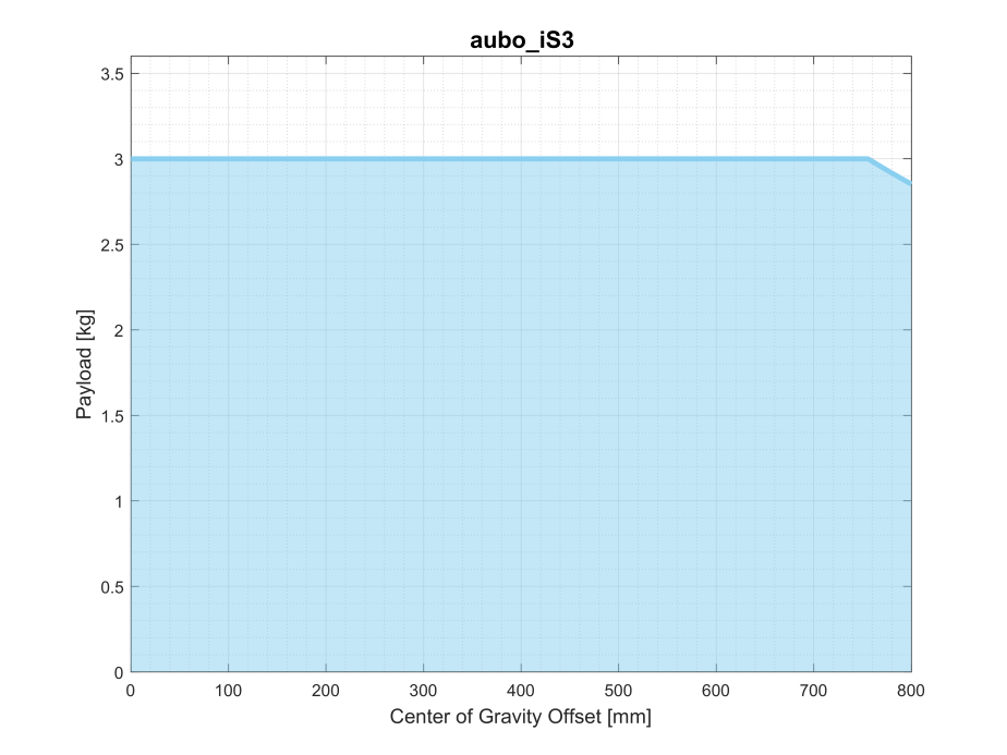

| Sign | Description |
|---|---|
| 1. The load conditions shall be within the range shown in the figure. 2. The load shown in the figure is the maximum payload of the robot arm, and in no case shall the maximum load shown in the figure be exceeded. 3. Otherwise, the internal components of the robot may be damaged. |
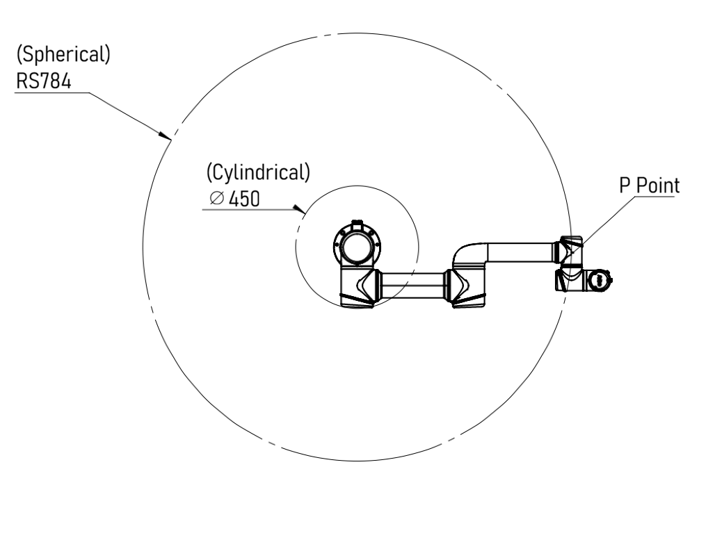
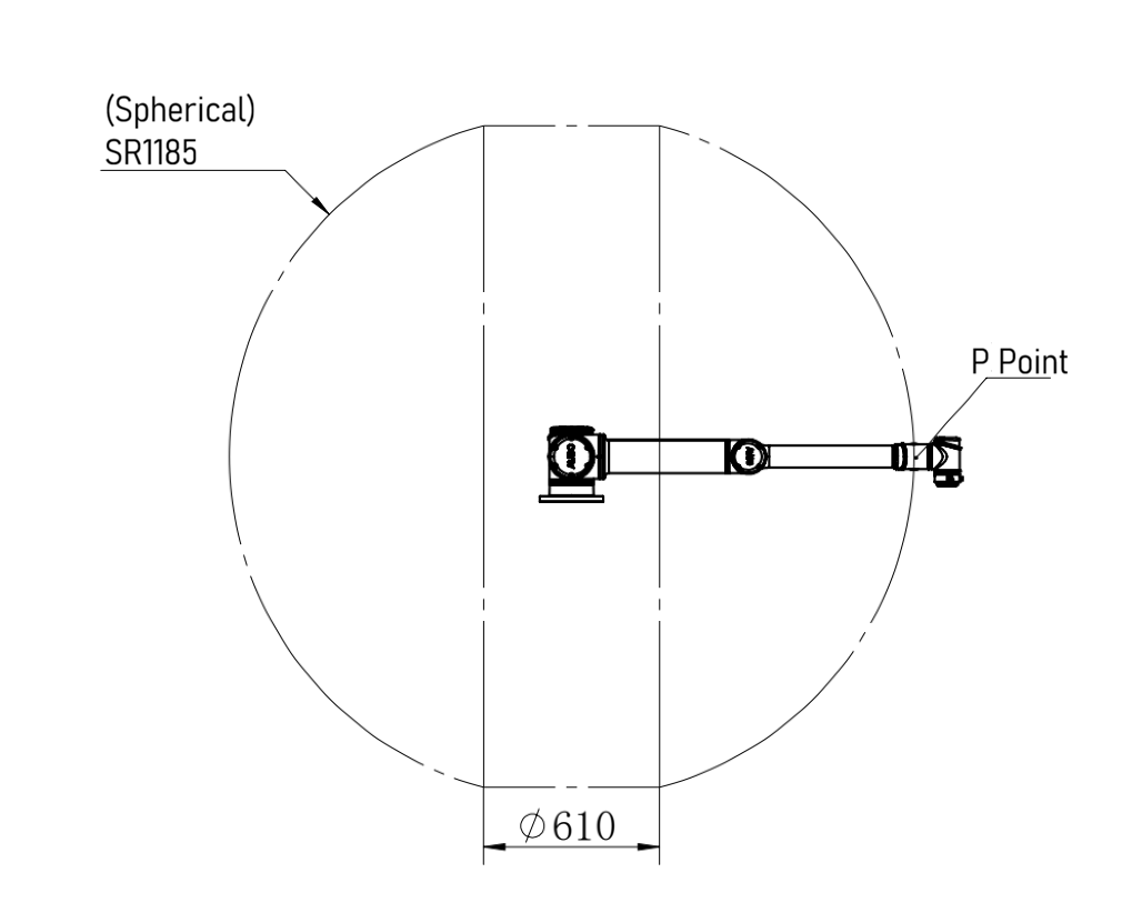
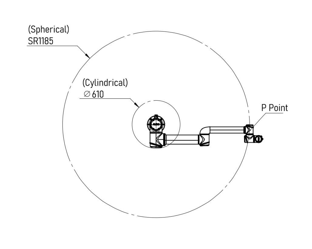
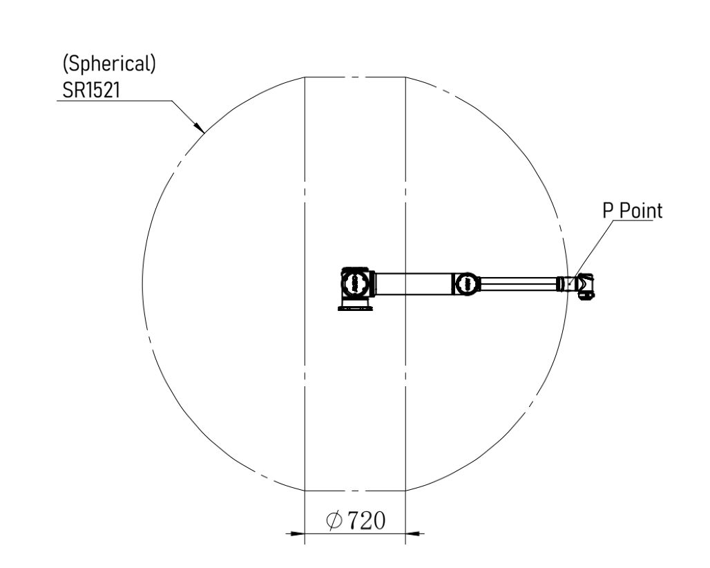
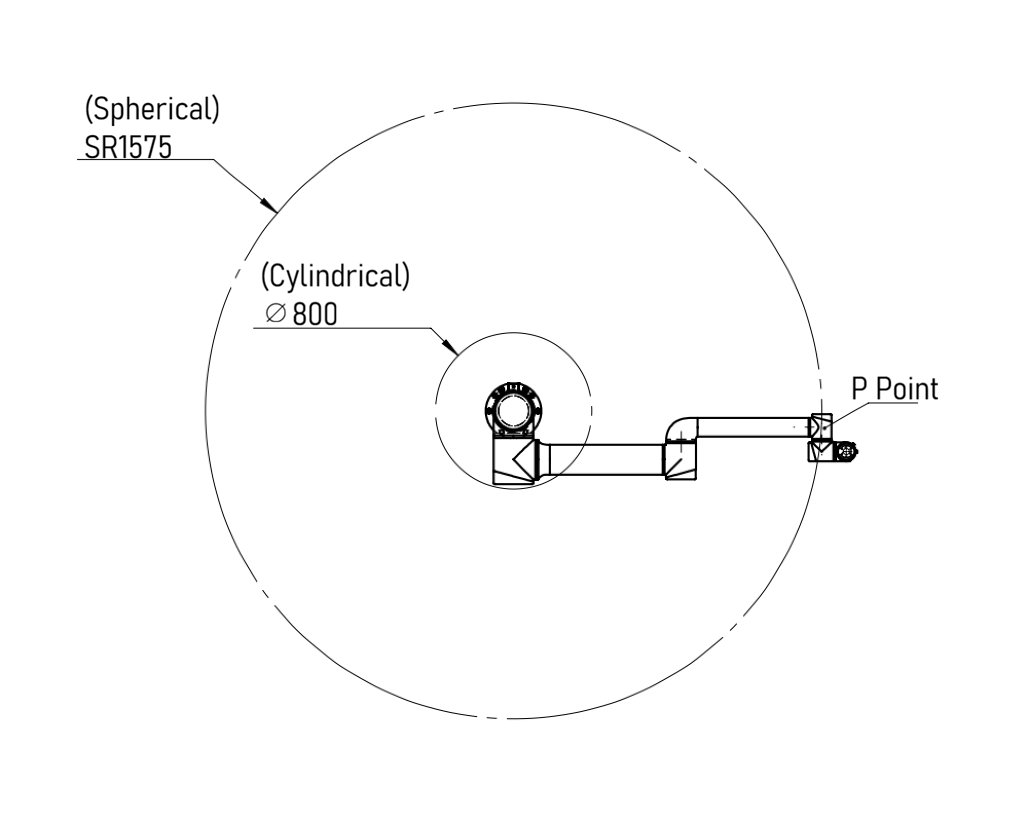
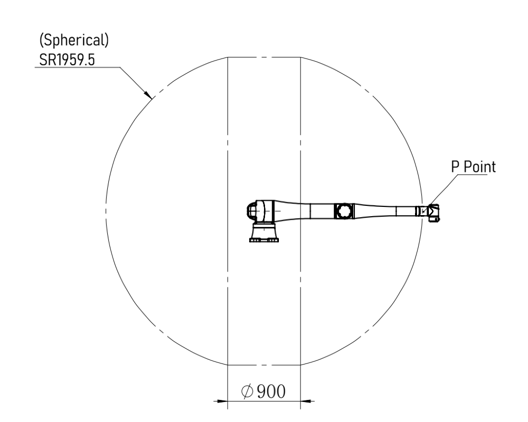
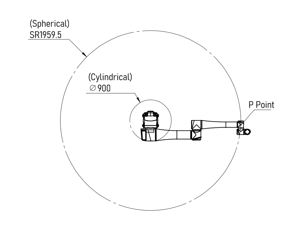
4.4 Robot arm's Workspace
4.4.1 Mechanical Dimensions
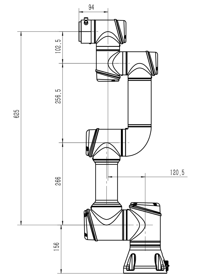


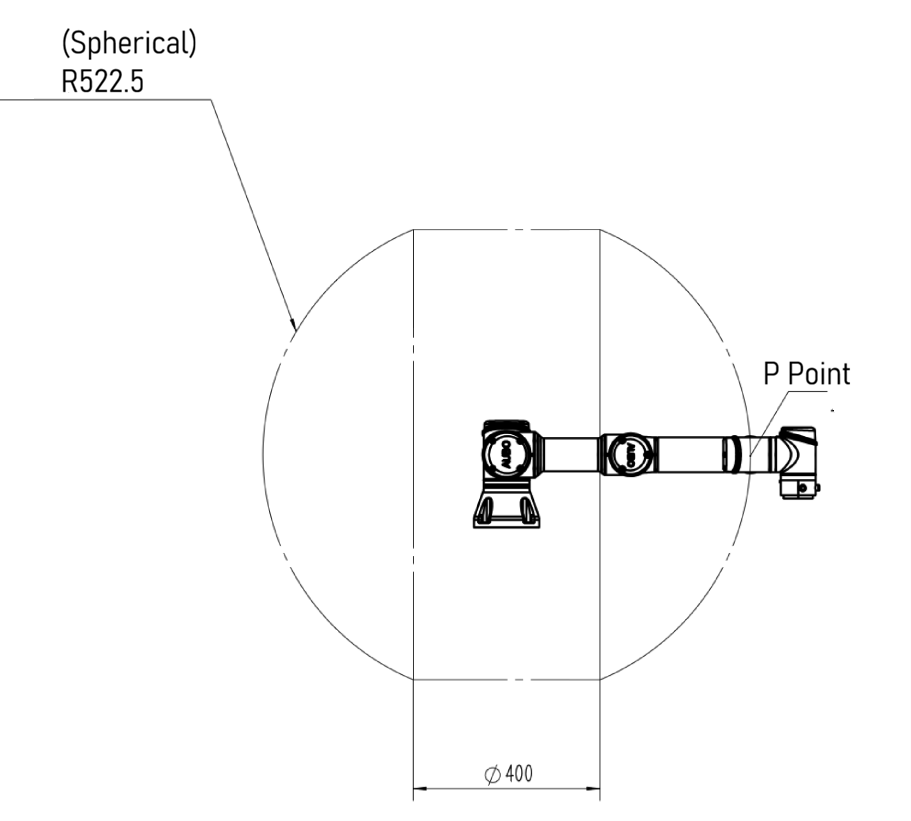
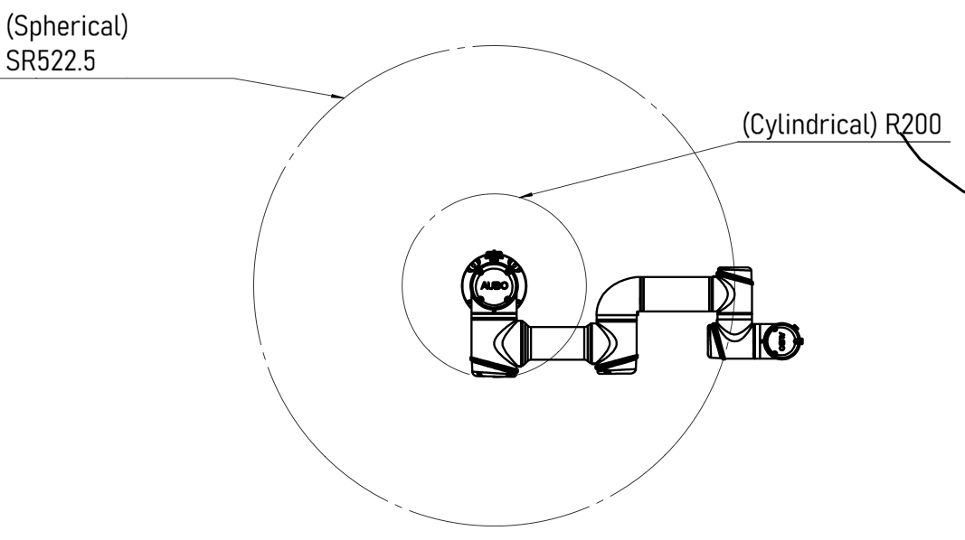
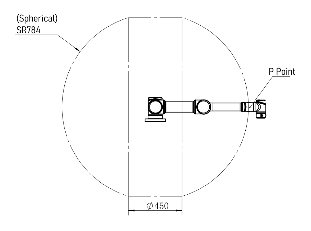
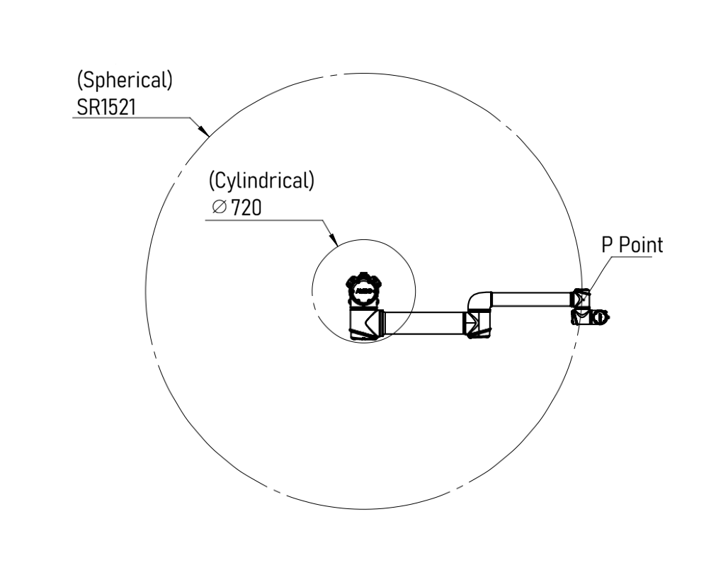
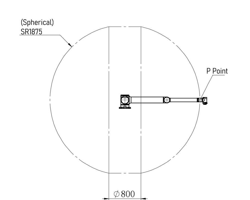
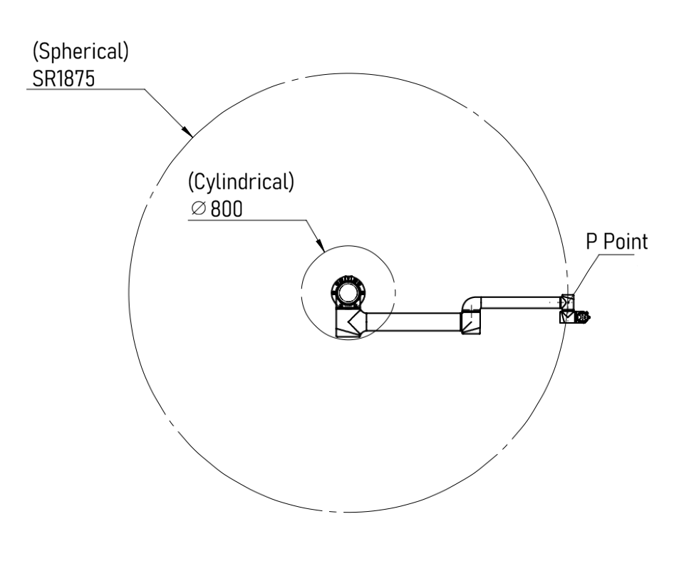
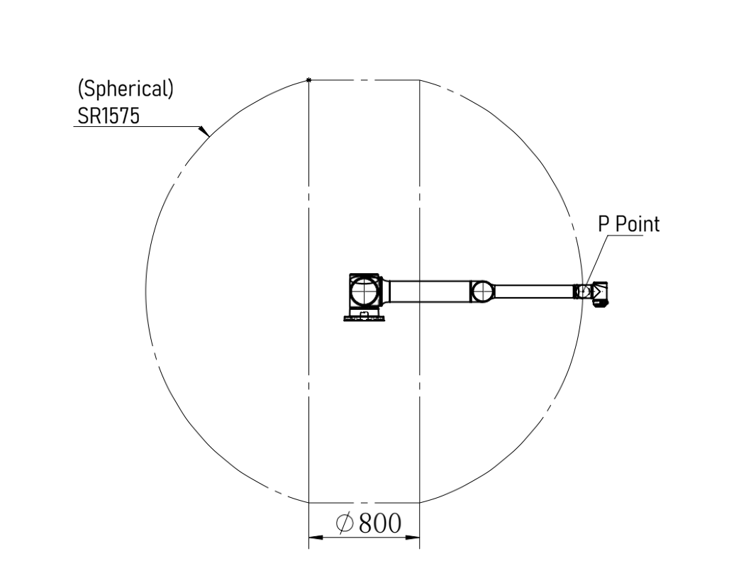
4.4.2 Moving Range of Point P
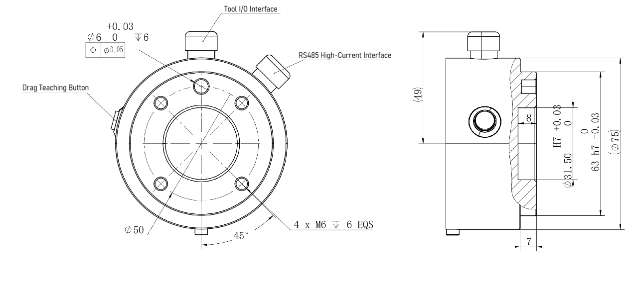
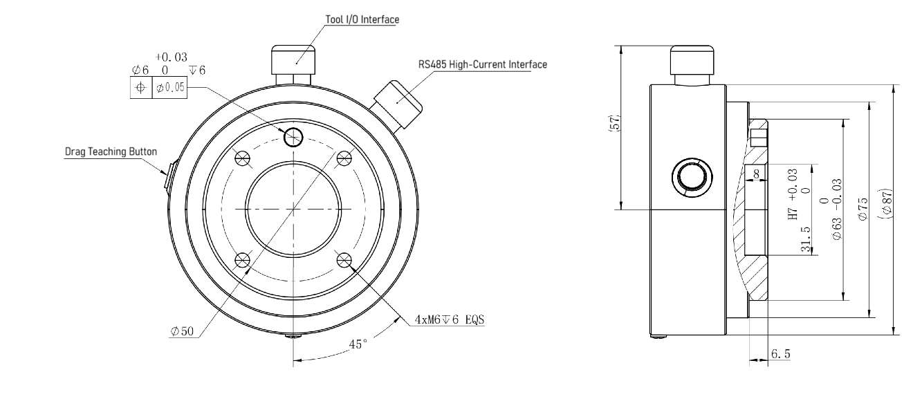
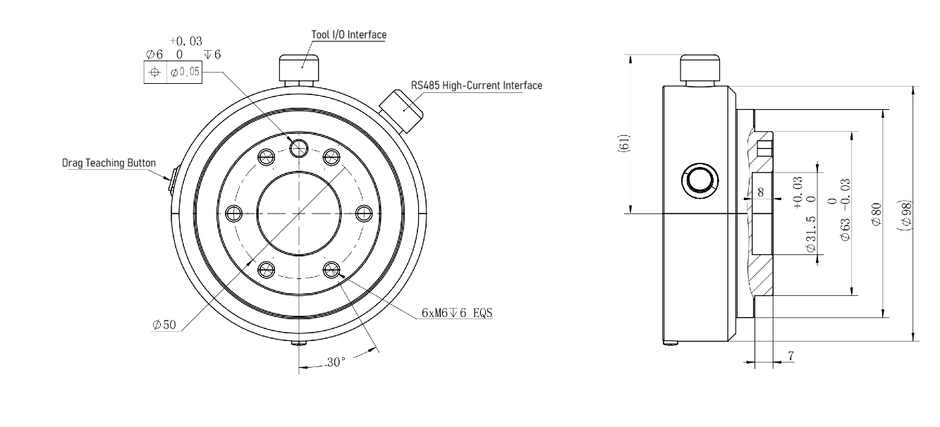
4.4.3 Mechanical Dimensions of Tool Flange
The end effector flanges used by different models of AUBO-iS series robot arm are slightly different. The end effector flange has several threaded holes and 1 locating hole. 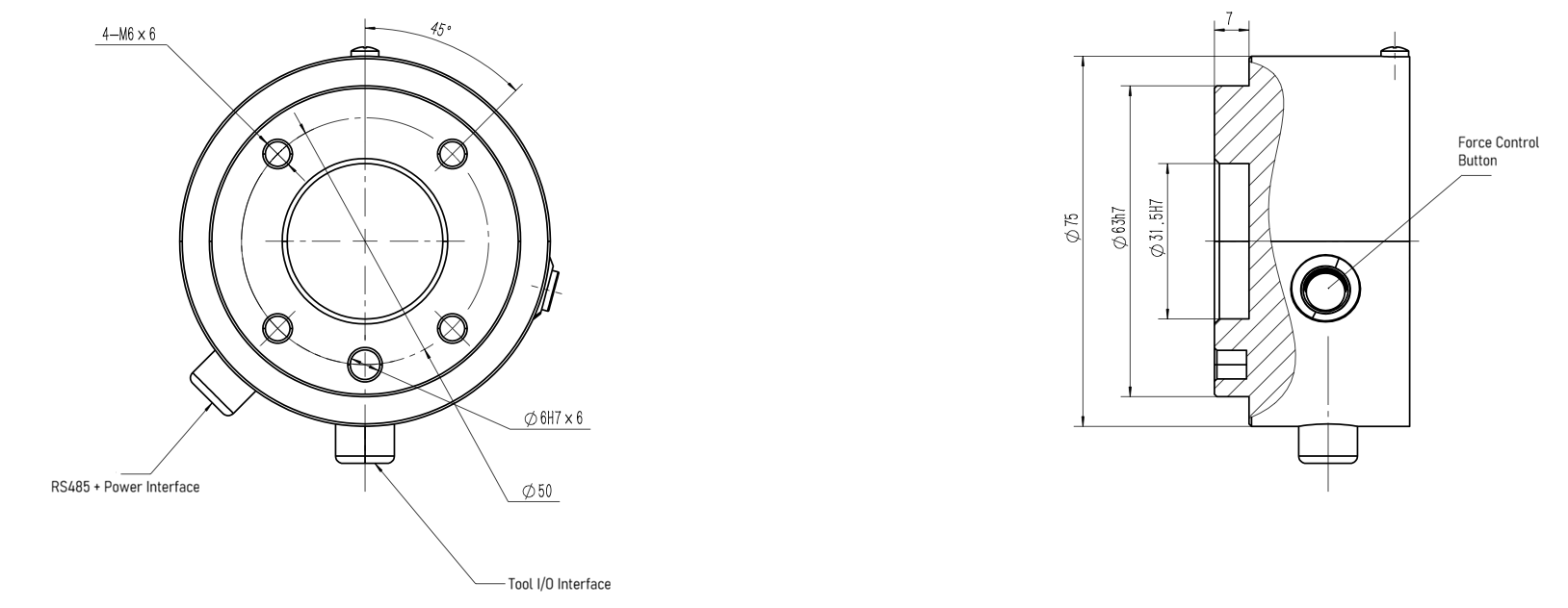

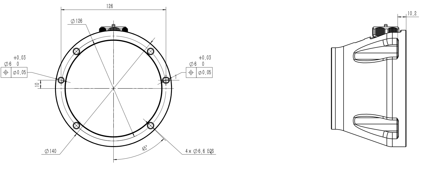
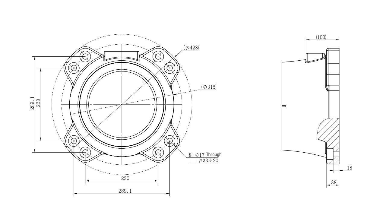
4.4.4 Top View of Base


5 Installation and Commissioning
5.1 Brief Installation Steps
Brief installation step of AUBO-iS series robot:
- Determine robot arm's workspace
- Install the robot arm body on the carriage
- Install the end-effector
5.2 Important Safety Instructions
| Sign | Description |
|---|---|
| Environmental conditions for installation: 1. No corrosive gas or liquid 2. No oil mist 3. No smoke 4. No dust or metal powder 5. No mechanical shock or vibration 6. No electromagnetic noise 7. No radioactive materials 8. Low humidity 9. No flammable materials 10. Ambient temperature: 0°C ~ 50°C 11. No direct sunlight (avoiding outdoor use) Bearing capacity of floor: Install the robot on a solid surface that is capable of withstanding at least ten times the full torsional force of the base joint and at least five times the weight of the robot arm. In addition, the floor surface shall be free from vibration. Instructions for installing additional components: If additional components not covered in the scope of supply of AUBO (Beijing) Intelligent Technology Co., Ltd., such as cables, are integrated into the robot, the user shall ensure that these components have no effect on and will not affect the safety functions. |
| 1. Be sure to carry out a safety assessment after each robot installation, in strict accordance with the instructions in Chapter 3 (Safety). 2. Place the controller horizontally on the ground, and maintain a 50 mm space on each side of the controller to ensure smooth air flow. 3. Hang the teach pendant on the controller if possible, and prevent the cable from being trampled. |
| 1. Do not wet controller, otherwise personal injury or death may be caused. 2. Monitor the presence of conductive dust. |
5.3 Robot Installation
5.3.1 Carriage (Optional)
The AUBO robot carriage is an optional component for supporting and fixing the robot arm. The selection of carriage depends on the model and payload of the robot to be installed. Figure 5-1 shows the diagram of carriage, and the actual product serves as the standard.
- Small-load carriage: This kind of carriage is equipped with 4 anchor bolts and 4 universal wheels for easy fixing and moving. When fixing the robot arm, rotate the upper part of the anchor bolt to lower the anchor bolt; when moving the robot arm, rotate the lower nut of the anchor bolt with a wrench to lift the anchor bolt and place the universal wheel on the ground.
- Large-load carriage: This kind of carriage is equipped with 4 anchor bolts for stable installation. When fixing the robot arm, rotate the torx wheel to adjust the anchor bolt height and tighten the nut with an adjustable wrench.
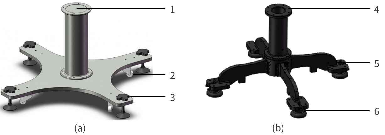
1, 4 - Contact surface between carriage and robot arm; 2 - Universal wheel; 3 - Anchor bolt; 5 - Nut; 6- Torx wheel
5.3.2 Robot Arm Installation
AUBO-iS series robot arm is designed with 360° installation position and posture adaption function, and thus supports various installation methods including carriage installation, suspension installation and wall installation, as shown in Figure 5-2. After the robot arm is installed, the teach pendant software will automatically recognize and adjust the working parameters of the robot arm after power-on.
When the robot is to be installed on a carriage, it is recommended to use 4 bolts and install dowel pins into 2 holes with slightly smaller diameters in advance to improve the installation accuracy. For mechanical dimensions, refer to 4.4.4 Top View of Base. 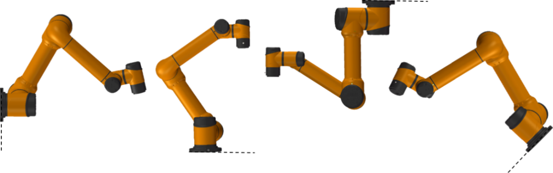
| Sign | Description |
|---|---|
| 1. Ensure that the robot arm is properly and securely installed in place. 2. Do not install the robot arm in water or in a humid environment, except for those rated at IP67 as declared. Otherwise, the robot arm may be damaged after long-term exposure to water. 3. Danger of tip-over: If the robot arm is not placed securely on a solid surface, it may tip over and cause damage. |
| 1. In case of installation on a carriage, keep the robot in close contact with the carriage. 2. It is recommended to use a carriage featuring a contact surface with strong heat dissipation performance, such as contact surface made of all-aluminum materials. When the working temperature exceeds 35 ℃, it is strongly recommended to use materials with strong heat dissipation performance. |
5.3.3 Installation of End-effector
The end-effector flange contains several threaded holes and 1 locating hole for fixing tools such as gripper to the end of the robot arm. For mechanical dimensions of the end effector flange, refer to 4.4.3 Mechanical Dimensions of Tool Flange.
| Sign | Description |
|---|---|
| 1. Ensure that the tool is correctly and securely installed in place. 2. Ensure that the tool safety architecture is such designed that there is no risk of accidental falling of parts. |
5.3.4 Protective Grounding
The power input terminal of the robot arm controller must be connected to a qualified protective grounding wire (PE wire), ensuring a sound electrical connection between the controller enclosure and the ground. It is strictly prohibited to power on the robot arm without connecting the protective grounding wire (PE wire).
Grounding Technical Requirements:
- Cable Specifications: The protective grounding wire (PE) must use a copper-core cable with a cross-sectional area of ≥ 2.5 mm². The insulation layer must be intact. Connection terminals must be crimped securely using professional crimping tools; wrapping connections are strictly prohibited.
- Grounding Resistance: After the grounding installation is completed, the grounding resistance must be measured between the robot arm's PE terminal and the ground using a grounding resistance tester. A resistance value of ≤ 4Ω is considered qualified.
- Record Keeping: Grounding test records must be retained for filing, serving as critical evidence for safety compliance. Safety Inspection and Maintenance:
- Routine Inspection: Operators shall regularly inspect the connection status of the PE wire to ensure there is no loosening, breakage, or corrosion.
- Maintenance Requirements: The grounding resistance must be retested after equipment maintenance, relocation, or reinstallation to ensure the continuous effectiveness of the grounding system.
- Training Requirements: All operators must receive grounding safety training to understand the risks of not being grounded and the correct grounding methods.
| Sign | Description |
|---|---|
| 1. It is strictly prohibited to power on the robot arm without connecting the protective grounding wire (PE wire). Failure to provide proper grounding may result in electric shock, abnormal electromagnetic interference, or permanent damage to the equipment. 2. When the robot arm is not connected to the PE wire, the enclosure may carry an induced voltage of 15V~105V. Contact with the enclosure may cause discomfort such as tingling or numbness, which could lead to panic-induced incorrect operation, secondary hazards including collision with the robot arm, or accidental emergency stop activation. |
5.3.5 Cable connection
After the robot arm is installed, the controller must be connected correctly before it can be powered on for normal use. For the cable connection method, please refer to the Controller User Manual.
5.4 Installation Precautions for Heavy-Load Robotic Arms
For robotic arms with a rated payload of 20kg or above, loss of motion control may cause irreversible severe injury or death. The following safety requirements must be strictly observed during the installation phase.
5.4.1 Pre-installation Preparation
- A comprehensive risk assessment of the installation scenario must be completed prior to installation. Identify potential hazards in hoisting, fixing, and electrical connection stages (e.g., mechanical crushing, falling objects, electric shock).
- All personnel involved in the installation must undergo specific training or provide proof of experience demonstrating their safety competence in handling heavy-load servo systems.
- For heavy-load robots, it is recommended to provide means of limiting their workspace (mechanical stops, electromechanical devices, or certified safety software).
- It is recommended to install safety guarding devices such as safety fences or light curtains. The height must be above 2000 mm (minimum no less than 1400 mm), and the ground clearance must not exceed 180 mm. Protective panel fasteners must use "captive bolts" to ensure panels are reliably reset after maintenance. The minimum safety distance (S) must be determined based on the approach speed of personnel (K), the stopping time of the robotic arm (T), and the intrusion distance (C), calculated using the formula: S = K × T + C
5.4.2 Handling and Hoisting Safety Standards
For robotic arms with a rated payload of 20kg or above, manual handling is strictly prohibited. Manual handling poses significant safety risks, including personal injury, falling objects, and equipment damage. Such robotic arms must be handled and hoisted using compliant, specialized equipment in full accordance with safety regulations.
When hoisting, the influence of the end-effector on the center of gravity must be considered; if necessary, it should be removed first.
Hoisting operations must be directed by a designated supervisor. Unauthorized personnel are prohibited from entering the operating radius during hoisting. Hoisting personnel must possess the corresponding safety competence qualifications.
5.4.3 Foundation Engineering Requirements
- Robotic arms with a rated payload of 20kg or above possess immense dynamic inertia. The installation ground must undergo professional structural calculation. To meet the requirements of ISO 10218-2:2025 for foundation stability, the following technical standards are recommended:
- Material Strength:
- The robot installation foundation should use reinforced concrete with a strength grade no less than C30 (equivalent to approximately 4000 psi). This ensures that anchor bolts do not loosen under the massive overturning moments generated during an emergency stop.
- Installation Precision:
- Surface flatness tolerance ≤ 0.5mm to prevent internal stress in the base casting during tightening.
- Surface inclination ≤ 0.5° to ensure the accuracy of the robot's gravity compensation algorithm and prevent joint overload caused by eccentric loads.
- The robotic arm body must utilize equipotential bonding. The grounding resistance must be ≤ 4Ω, with grounding terminals firmly connected and free of looseness. Grounding cable specifications must match the power requirements of the robotic arm.
5.5 Arm-side Interfaces and Buttons
5.5.1 Introduction
In order to meet different requirements of end-effector, the AUBO-iS series robot arm is designed with an 8-pin connector (hereinafter referred to as "tool I/O interface"), a 4-pin connector (hereinafter referred to as "tool RS485 interface") and a "HandGuide" button at the wrist. The tool RS485 interface is an optional configuration. 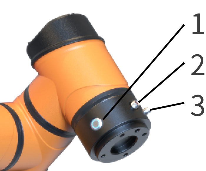
1 - "HandGuide" button; 2 - Tool I/O interface; 3 - Tool RS485 interface
5.5.2 Tool I/O interface
The tool I/O interface integrates power supply and signal transmission capabilities, supports the connection and control of end effectors such as gripper and sensors, and is connected by industrial-grade cable containing 8 function wires (as shown in Figure 5-4 and Table 5-1). The power supply voltage, digital I/O interface mode, I/O interface function, etc. can all be configured in the teach pendant software. For configuration methods and functions, please refer to the AuboStudio User Manual. 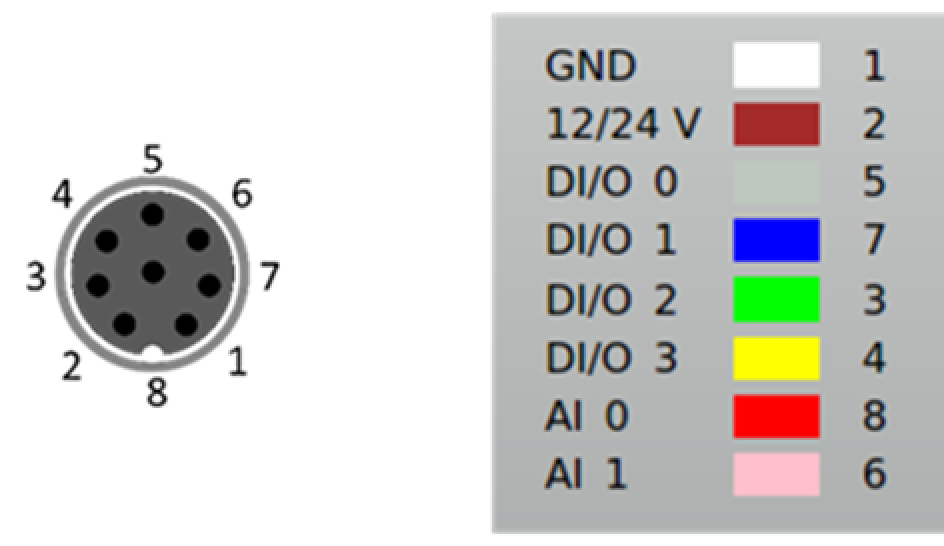
| Color | Signal | Pin | Color | Signal | Pin |
|---|---|---|---|---|---|
| White | GND | 1 | Green | DI/O 2 | 3 |
| Brown | 12/24V | 2 | Yellow | DI/O 3 | 4 |
| Grey | DI/O 0 | 5 | Red | AI 0 | 8 |
| Blue | DI/O 1 | 7 | Pink | AI 1 | 6 |
For the tool I/O interface, the digital I/O interfaces are designed based on the NPN switching scheme:
- Digital input mode: the connector is driven to connect to ground when digital input mode is activated, and is open when the digital input mode is deactivated;
- Digital output mode: the low-voltage pull-down resistor is equipped to ensure the stability and reliability of the signal. For detailed electrical parameters of the tool I/O interface, see Table 5-2 to Table 5-4, with electrical error controlled within ±10%.
| Parameter | Minimum | Typical | Maximum | Unit |
|---|---|---|---|---|
| Power supply voltage in 24 V mode | 23 | 24 | 25 | V |
| Power supply voltage in 12 V mode | 11.5 | 12 | 12.5 | V |
| Power supply current in both 24V and 12V modes | - | 0.8 | 1.0 | A |
| Parameter | Minimum | Typical | Maximum | Unit |
|---|---|---|---|---|
| Input voltage range | 0 | - | 10 | V |
| Voltage resolution | - | 2.5 | - | mV |
| I/O type | Parameter | Minimum | Typical | Maximum | Unit |
|---|---|---|---|---|---|
| DI interface | Input voltage | -0.5 | - | Vout+2 | V |
| Logic low voltage | 0 | 1.5 | 2 | V | |
| Logic high voltage | Vout-4 | Vout | Vout+2 | V | |
| Input resistance | - | 4.3 | - | kΩ | |
| DO interface | Open-circuit voltage | Same as current power supply | |||
| Voltage at 1A input current | 0.35 | 0.4 | 0.85 | V | |
| Input current | 0.35 | 0.4 | 0.5 | A | |
| Current through GND | 0.35 | 0.4 | 0.5 | A | |
| AI interface | AI 0 | 0 | - | +10 | V |
| AI 1 | 0 | - | +10 | V | |
| Sign | Description |
|---|---|
| It is required to ensure that, when a tool or gripper is connected, no danger will occur when the power supply is interrupted, such as the workpiece falling from the tool. |
5.5.3 Tool RS485 Interface (Optional)
The tool RS485 interface provides fieldbus communication capabilities, supports direct communication and data exchange of multiple devices via standard RS485 communication protocol, and is connected by industrial cable containing 4 function wires (as shown in Figure 5-5 and Table 5-5). Its power supply voltage is configured in the same way as that of the tool I/O interface. For configuration methods and functions, please refer to the AuboStudio User Manual. For relevant electrical parameters, please refer to Table 5-2. 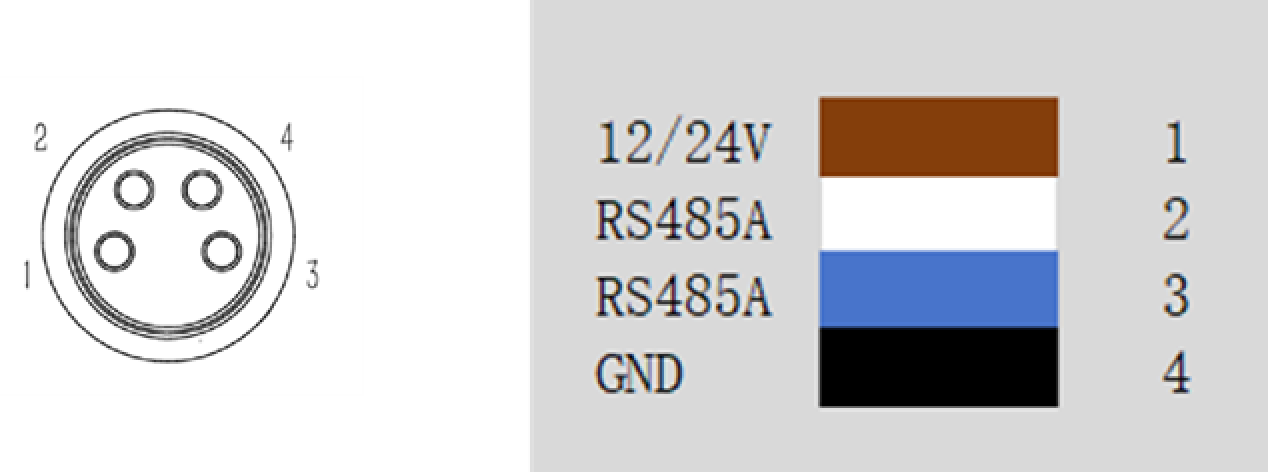
| Color | Signal | Pin |
|---|---|---|
| Brown | 12/24V | 1 |
| White | RS485A | 2 |
| Blue | RS485B | 3 |
| Black | GND | 4 |
5.5.4 HandGuide Button
The "HandGuide" button is a human-computer interaction component provided for the AUBO-iS series robot arm. When it is pressed without release, the HandGuide mode of the robot arm will be enabled, allowing the user to move the robot arm easily; After the button is released, the robot arm maintains the current attitude and the HandGuide mode is disabled. This function can be used in conjunction with the "trajectory recording" function. For details, please refer to AuboStudio User Manual.
6 Handling and Precautions
When hoisting the robot, secure the moving parts by appropriate measures to prevent accidental movement during hoisting and transportation, which will cause unexpected damage. During packaging for transportation, carry out the packaging according to the packaging standard, and make marks on the outside of the packaging box as required.
During transportation, ensure that the robot is stable and fixed in a proper position.
Lift the controller with a handle.
When moving the robot from the robot packaging material to the installation position, hold the robot until all the bolts of the robot base are tightened.
After fixing, power on the robot, and adjust the robot attitude as appropriate using the HandGuide function.
Keep the original packaging after transportation. Store the packaging material in a dry place for future use when the robot needs to be repacked and transferred.
| Sign | Description |
|---|---|
| 1. Make sure that your back or other body parts are not overloaded when lifting the equipment. 2. Follow all regional and national guidelines. AUBO (Beijing) Intelligent Technology Co., Ltd. shall not be responsible for any damage arising from improper transportation. 3. Make sure that the robot is installed in strict accordance with the installation instructions in the manual. |
7 Maintenance
Maintenance operations must be done in strict accordance with all safety instructions herein.
The maintenance, calibration and repair work must be performed according to the latest service manual, which is available on the website: www.aubo-robotics.cn. All dealers of AUBO (Beijing) Intelligent Technology Co., Ltd. are authorized to access this website.
Maintenance must be carried out by an authorized system integrator or AUBO (Beijing) Intelligent Technology Co., Ltd. Parts shall be returned to AUBO (Beijing) Intelligent Technology Co., Ltd. in accordance with the instructions in service manual.
The maintenance must be carried out with the specified safety level secured and according to the currently effective national or regional work safety regulations, and all safety functions shall be tested for normal working.
The maintenance is intended to secure the normal operation of the system or to recover a faulty system to normal. Maintenance includes fault diagnosis and repair.
The following safety procedures and precautions must be followed to operate the robot arm or controller:
| Sign | Description |
|---|---|
| 1. Disconnect the main input cable from the back of the controller to ensure that it is completely powered off. Take necessary measures to prevent authorized personnel from re-connecting the power supply to the system during maintenance. After the power supply is cut off, check the system again to ensure that it is powered off. 2. Check the ground connection before restarting the system. 3. Follow the ESD (electrostatic discharge) regulations when disassembling the robot arm or controller. 4. Avoid disassembling the power supply system of the controller. Pay attention that the power supply system of the controller will remain at high voltage for several hours after the controller is turned off. 5. Prevent water or dust from entering the robot arm or controller. 6. Replace the faulty parts with new parts of the same part number or the equivalent parts approved by AUBO (Beijing) Intelligent Technology Co., Ltd. 7. Enable all disabled safety measures immediately after the maintenance is completed. 8. Record all maintenance operations in writing and keep it in the technical documentation related to the robot system. 9. The controller contains no parts that can be repaired by the end user. If maintenance or repair services are required, please contact your dealer or AUBO (Beijing) Intelligent Technology Co., Ltd. |
8 Disposal
AUBO robot must be disposed of in accordance with applicable national laws and regulations and national standards.
9 Warranty
9.1 Warranty
AUBO robots feature a limited warranty period of 18 months.
If the new equipment or any of its component exhibits defects resulting from poor manufacturing and/or material within 18 months from the start of use, AUBO (Beijing) Intelligent Technology Co., Ltd. shall provide the necessary spare parts for replacement or repair.
AUBO (Beijing) Intelligent Technology Co., Ltd. has the ownership of the equipment or components replaced or returned to the AUBO (Beijing) Intelligent Technology Co., Ltd.
When the warranty expires, AUBO (Beijing) Intelligent Technology Co., Ltd. reserves the right to charge the customer for replacement or repair.
If the equipment is defective outside the warranty period, AUBO (Beijing) Intelligent Technology Co., Ltd. shall not be liable for any damage or loss arising therefrom, such as production loss or damage to other production equipment.
9.2 Disclaimer
The warranty will be invalid if the defect is caused by improper handling or failure to follow the relevant information in the User Manual.
Faults caused by the following conditions are not covered by this warranty:
Purchase of products through channels not approved by AUBO;
Failure to perform installation, wiring and connection of other control device in accordance with industrial standards or the requirements in the User Manual;
Use of this product beyond the nominal specifications or standards;
Use of this product for purposes other than those specified;
Use of this product in environmental conditions out of the nominal settings;
Use of this product in a grinding environment or a special use environment without protection;
Product damage due to improper transportation;
Failure, damage or consequential damage caused by accidents or human factors;
Failure, damage or consequential damage caused by modification;
Use of non-genuine parts and accessories;
Damage caused by modification, commissioning or repair of original parts by a third party other than AUBO (Beijing) Intelligent Technology Co., Ltd. or its designated integrator;
Failure, damage or consequential damage caused by natural disasters or other force majeure;
Faults not related to the responsibility of AUBO (Beijing) Intelligent Technology Co., Ltd., apart from those mentioned above.
Warranty will not be provided in following circumstances:
Failure to identify product traceability number.
Failure to identify the date of manufacture or the warranty start date.
Changes to software or internal data.
Failure to reproduce the fault or failure to identify the fault by AUBO (Beijing) Intelligent Technology Co., Ltd.
Use of this product in radioactive equipment, biological test equipment or in other dangerous applications ascertained by AUBO (Beijing) Intelligent Technology Co., Ltd.
Appearance parts and wearing parts. According to the warranty agreement, AUBO (Beijing) Intelligent Technology Co., Ltd. will only provide warranty services for defects and deficiencies of the products and parts sold to dealers.
AUBO (Beijing) Intelligent Technology Co., Ltd. shall not be liable for any other express or implied warranties or liabilities, including but not limited to any implied warranties for merchantability or fitness for a specific use. In addition, AUBO (Beijing) Intelligent Technology Co., Ltd. shall not be liable for any indirect damage or consequences of any kind arising from the relevant products.
10 Appendix A Glossary
Category 0 stop: Robot motion is stopped by immediate removal of power to the robot. This is an uncontrolled stop, where the robot may deviate from the programmed path because each joint brakes as fast as possible. This protective stop is used if the safety assessment limit is exceeded or in case of a fault in the safety-related parts of the control system. For more information, see EN ISO 13850:2008 or IEC60204-1:2006.
Category 1 stop: Robot motion is stopped with power available to the robot and then the power is removed when the stop is achieved. It is a controlled stop, where the robot will continue moving along the programmed path. Power is removed after one second or as soon as the robot stands still. For more information, see EN ISO 13850:2008 or IEC60204-1:2006.
Category 2 stop: Category 2 stop is a controlled stop with power left available to the robot. The robot stops all motions within one second. The safety-related control system monitors that the robot stays at the stop position. For more information, see IEC60204-1:2006.
Diagnostic coverage (DC): Diagnostic coverage is a measure of the effectiveness of the diagnostics implemented to achieve the rated performance level. For more information, see EN ISO 13849-1:2008.
Integrator: The integrator is the entity that designs the final robot installation, which is responsible for performing final risk assessment and must ensure that the final installation of robot complies with local laws and regulations.
Mean Time to Dangerous Failure (MTTFd): Mean Time to Dangerous Failure (MTTFd) is a value based on calculations and tests used to achieve the rated performance level. For more information, see EN ISO 13849-1:2008.
Risk assessment: A risk assessment is the overall process of identifying all risks and reducing them to an appropriate level. A risk assessment should be documented. For more information, see ISO 12100.
Performance level: Performance level (PL) is a discrete level used to specify the ability of safety-related parts of control system to perform a safety function under foreseeable conditions. PLd is the second highest reliability classification, meaning that the safety function is extremely reliable. For more information, see EN ISO 13849-1:2008.