AUBO-CB-iS Series Control Box User Manual
1 About this Manual
1.1 Version information
v1.2.0
The User Manual will be regularly checked and corrected, and the updates will be incorporated in the new version. The information in this manual is subject to change without notice.
AUBO (Beijing) Intelligent Technology Co., Ltd. shall not be liable for any errors or omissions in this Manual, or for any accidental or consequential injuries arising from the use of this Manual and the products described therein.
Please read this manual before installing and using the product described herein.
Please keep this manual for the convenience of reading or reference when necessary.
All pictures in this manual are for reference only and the product received serves as the standard.
This Manual is the exclusive property of AUBO (Beijing) Intelligent Technology Co., Ltd. and may not be copied, reproduced in whole or in part, or converted into any other form for use without the written permission of AUBO (Beijing) Intelligent Technology Co., Ltd.
Copyright © 2015-2026 AUBO All rights reserved.
This publication is the User Manual of AUBO-CB-iS series control box, and applies to the following products: AUBO-CB-iS and AUBO-CB-iS-H.
Use of this Manual
This Manual is applicable to the installation, commissioning, maintenance, repair and disassembly of AUBO-CB-iS series control box.
Intended readers
This Manual is intended for the following professionals:
Installation personnel;
Maintenance personnel;
Repair personnel.
Preconditions for operation
Readers are required to have the following basic knowledge and qualifications:
Professional training experience by AUBO;
Knowledge about installation, maintenance and repair of mechanical and electronic devices;
Basic awareness of safe operation.
Associated documents
User Manual of AUBO-iH series, AUBO-iS series and AUBO-C5 robot arm
AuboStudio User Manual
Additional information
For more information, please visit our official website at: www.aubo-robotics.cn
2 Revision
| Version / Time | Description |
|---|---|
| v1.2.0*/20251010 | v1.2.0* (Trial) released. |
3 Safety
3.1 Warning Signs
Integrators and users must read this Manual carefully, especially the content with warning signs, which must be mastered and strictly observed. Industrial robot system is complex and potentially dangerous. Users must have a comprehensive safety awareness, deeply understand the possible risks in the operation process, and strictly abide by the industrial robot safety requirements in ISO 10218.
The safety-related content in this Manual are indicated by the following warning signs. The content indicated by warning signs in this Manual represent important reminders for personal safety and equipment safety, and users must fully understand and strictly follow them.
| Sign | Description |
|---|---|
 | It indicates a possibly hazardous situation that, if not avoided, could result in death or serious injury. |
 | It indicates a possibly hazardous situation, if not avoided, could result in injury to personnel or major damage to equipment. |
 | It indicates a possibly hazardous situation, if not avoided, could result in injury to personnel or damage to equipment. Attention shall be paid that the hazards indicated by this sign may sometimes cause more significant consequences, depending on the specific circumstances. |
 | It indicates a situation that, if not avoided, could result in injury to personnel or damage to equipment. Attention shall be paid that the hazards indicated by this sign may sometimes cause more significant consequences, depending on the specific circumstances. |
3.2 Safety Precautions
3.2.1 Instructions for Use
The following basic information needs to be understood and followed when the robot is used for the first time. Also, other safety-related information will be introduced in other parts of this manual. However, it may not cover all don'ts and prohibitions due to the presence of so many possibilities.
| Sign | Description |
|---|---|
| 1. Always install the machine and all electrical equipment in accordance with the requirements and specifications herein. 2. Make sure to perform a preliminary test and inspection of the machine and its protection system before using the robot or putting it into production for the first time. 3. Before starting the robot or robot system for the first time, check whether the robot or robot system is in good condition and safe for operation, without any damage detected; and test, with all safety functions covered, whether the currently effective national or local safety production rules and regulations are satisfied. 4. Always check that all safety parameters and user programs are correct and that all safety functions are working properly, which must be done by personnel qualified to operate the robot. Do not start the robot until it has passed the thorough safety test, proving that it reaches the specified safety level. 5. Always get the installation and commissioning performed by professionals according to the installation standards. 6. When the robot is installed, carry out a comprehensive risk assessment again and keep a record therefor. 7. Always get the setting and modification of safety parameters carried out by authorized personnel, and apply security measures such as password or isolation measure to prevent their unauthorized modification or setting. After the safety factor is modified, be sure to analyze the relevant safety functions. 8. In case of an accident or abnormal operation, press down the emergency stop button to stop the robot if necessary. 9. The controller generates heat during operation. Do not operate or touch the robot when it is working or immediately after it stops. Instead, cut off the power supply and wait for an hour until the robot cools down. 10. Do not put your fingers in the heating part of the controller. |
| 1. Ensure that the machine is correctly and safely installed in place. 2. Stop using the robot when it is damaged. 3. Do not connect safety devices to general-purpose I/O interfaces, and instead, please use safety-related interfaces only. 4. Ensure the correct installation and settings. 5. Since connection of different machines may increase the risk or lead to new dangers, always perform a comprehensive risk assessment for the entire installation. When different safety and emergency shutdown performance levels are required, always select the highest one. Always read and understand the manuals of all equipment used in the installation. 6. Do not modify the robot, as any changes to the robot may cause unpredictable danger to the integrator. Carry out robot restructuring with authorization and according to the latest version of all relevant service manuals. If the robot is changed or altered in any way, AUBO (Beijing) Intelligent Technology Co., Ltd. disclaims all liability. 7. Before transporting the robot, check the insulation and protection measures. 8. Follow the transportation requirements when transporting the robot, and handle it carefully to avoid bumps. |
| 1. When the robot is combined with or working together with other machine that can cause robot damage, it is strongly recommended to check all functions of the robot separately. 2. AUBO (Beijing) Intelligent Technology Co., Ltd. shall not be liable for any robot damage or personal injury caused by improper operation. 3. Do not expose the robot to a permanent magnetic field, as strong magnetic fields can damage the robot. |
3.2.2 Operator Safety
Operator safety is the first consideration that must be secured during the operation of the robot system. The general precautions are listed in the table below, and appropriate measures shall be taken to ensure the safety of operators.
| Sign | Description |
|---|---|
| 1. Each operator using the robot system shall be trained through the training courses hosted by AUBO (Beijing) Intelligent Technology Co., Ltd. Users shall fully grasp the safe and standardized operating procedures with the robot operating qualifications. Please inquire for training details via email support@aubo-robotics.cn. 2. Do not wear loose clothes or jewelry when working with the robot systems, and make sure long hair is combed up at the back of the head. 3. When the robot is running, even if it appears to have stopped, it is possible that the robot is waiting for a start signal and in the state of imminent action, and even in such state, the robot should be considered as being in motion. 4. In emergency and abnormal situations, for example, when an operator is caught in or surrounded by a robot, push or pull the robot arm with force to force the joint to move. Manual movement of the robot arm without electric drive is for emergency use only, and may cause damage to the robot arm joint. |
3.3 Responsibilities and Regulations
The AUBO-CB-iS series controller can be combined with other equipment to form a complete machine and itself is not complete. Therefore, this Manual does not cover the instructions on how to design, install and operate a complete robot, nor does it cover all peripheral equipment that can influence the safety of the complete system. The safety of a complete robot installation depends on its integration. The integrator shall conduct risk assessment on the design and installation of the complete system in accordance with laws, regulations, safety codes and standards where the robot is installed. Risk assessment is one of the most important tasks that an integrator must do. Guidance on the risk assessment process may be found in the following standards.
ISO 12100:2010 Safety of Machinery - General Principles for Design - Risk Assessment and Risk Reduction;
ISO 10218-2:2025 Robots and Robotic Devices - Safety Requirements for Industrial Robots - Part 2: Robot Systems and Integration;
RIA TR R15.306-2014 Technical Report - Industrial Robots and Robot Systems - Safety Requirements - Task-based Risk Assessment Methodology;
ANSI B11.0-2010 Safety of Machinery; General Requirements and Risk Assessment.
The responsibilities to be fulfilled by an integrator include but are not limited to:
comprehensive risk assessment of complete robot system;
confirmation of the correctness of the system's design and installation;
provision of training to users and staff;
development of the operation specification of the complete system with specific operation process defined;
development of appropriate safety measures;
adoption of appropriate methods to eliminate hazards or minimize any hazards to an acceptable level at the time of final installation;
communication of residual risks to end users;
marking of the integrator's logo and contact information on the robot;
archiving of relevant technical documents.
For applicable standards and laws, please visit: www.aubo-robotics.cn.
All safety information contained herein shall not be regarded as a guarantee from AUBO (Beijing) Intelligent Technology Co., Ltd. It should be understood that, even if all safety instructions referred to herein are observed, personal injury or equipment damage is still likely to occur.
AUBO (Beijing) Intelligent Technology Co., Ltd. is committed to continuously improving the reliability and performance of its products, and therefore reserves the right to upgrade products without notice. AUBO (Beijing) Intelligent Technology Co., Ltd. will make every possible effort to ensure the accuracy and reliability of the information in this manual, but shall not be liable for any errors or omissions therein.
3.4 Intended Use
The AUBO-CB-iS series controller can be used in general industrial equipment and general commercial equipment. It is only allowed to be used under the specified environmental conditions. For specific information about the operating environment and operating conditions, please refer to the technical specification table.
The AUBO-CB-iS series controller has special safety level features and can be used in general industrial equipment and general commercial equipment. The use of sharp end effectors or tool connectors may be dangerous;
NOT used in flammable, explosive and other hazardous environments;
NOT used in devices for moving or carrying persons or other animals;
NOT used in medical equipment and other devices involving human life;
NOT used in devices that have a significant impact on society and publicity;
NOT used in vehicles, ships, etc. subject to vibration;
NOT used as climbing tools.
3.5 Emergency Response
3.5.1 Emergency Stop Device
Pressing the emergency stop button will immediately stop all motions of the robot. Emergency stop is not intended as a risk reduction measure, but as a secondary protection device. When multiple emergency stop buttons are to be connected, they must be included in the risk assessment of robot application. The emergency stop button meets the requirements of IEC 60947-5-5.
The controller is also equipped with an external emergency stop button interface (as shown), which can be used by the integrator or user according to the actual situation.
| Sign | Description |
|---|---|
| Tooling or equipment connected to the end of the robot arm must be integrated into the emergency stop circuit of the system if they pose a potential threat. Failure to comply with this warning may result in death, serious personal injury or major property damage. |
3.5.2 Recovery from Emergency Stop State
All emergency stop devices designed in the form of a button feature a "lock", which must be unlocked to end the emergency stop state.
The "lock" can be unlocked by rotating the emergency stop button.
| Sign | Description |
|---|---|
| Recovering from the emergency stop state is a simple but very important step, which can be operated only when the danger of the robot system is confirmed to be completely eliminated. |
4 Description of Control Boxes
4.1 AUBO-CB-iS Series
The AUBO-CB-iS series control box includes two models: AUBO-CB-iS and AUBO-CB-iS-H.
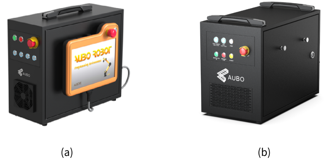
(a) AUBO-CB-iS; (b) AUBO-CB-iS-H
| Sign | Description |
|---|---|
| The AUBO-CB-iS control box is compatible with AUBO-iH series, AUBO-iS series, and AUBO-C series robot arms. The AUBO-CB-iS-H control box is only compatible with AUBO-iS35 robot arm. |
The controller is the control center of the AUBO robot, which contains the control main board, safety interface board, switching power supply, safety protection components, etc. The controller is powered by 100V-240V AC. The internal switching power supply converts 100V-240V AC into 12V, 24V and 48V DC to supply power for the load and robot in the controller. Before use, be sure to check whether the connection between the robot and teach pendant and the controller is reliable.
There are hardware protection and software protection in the controller to ensure the safety during use to the greatest extent. Multiple circuit breakers are used inside the controller, providing reliable short-circuit protection and overload protection on the hardware. There is an emergency stop button on the front panel of the controller, so that the user can cut off the power of the robot in the shortest time to protect the safety of personnel and equipment.
| Sign | Description |
|---|---|
| 1. There are 100V ~ 240V AC and 48V DC dangerous voltage in the controller. Non-professionals must not open the controller with power on. 2. Do not directly touch the fastening screws and other metals inside the controller with the hands, and do not remove the wires with power on. |
| The robot system only supports the upgrade and use of the default software. It is forbidden to install other software such as ROS. If there is a need to install software, it is recommended that users use other platforms to install it. |
4.2 Technical Specifications
4.2.1 AUBO-CB-iS
| Control Box Type | AUBO-CB-iS | |
| Dimensions (length * height * width) | 400mm * 320mm * 160mm | |
| Weight | 12.5kg (27.5lbs) | |
| Operating Temperature | 0℃ ~ 50℃ | |
| Operating Humidity | 90% RH (non-condensing) | |
| Transportation and Storage temperature | -25℃ ~ 55℃ | |
| IP rating | IP43 | |
| Power Supply | 100V ~ 240V AC, 50Hz ~ 60Hz | |
| I/O Power Supply | 24V 3A | |
| I/O Port | Digital input | 16 (general) + 16 (configurable) |
| Digital output | 16 (general) + 16 (configurable) | |
| Analog input | 2 | |
| Analog output | 2 | |
| Incremental encoder | 1 | |
| RS485 | 1 | |
| Wireless Module | Optional | |
| Communication Protocol | Ethernet, Modbus-RTU/TCP, Profinet, Ethernet/IP (optional) | |
| Interface and Openness | SDK (C/C++/C#/Lua/Python/JavaScript Windows + Linux systems), supporting ROS/ROS2 system, API | |
| Connecting Cable | Robot arm connecting cable | 5m (customizable, up to 8m) |
| Teach pendant connecting cable | 4m | |
| Connecting power cable | 5m | |
4.2.2 AUBO-CB-iS-H
| Control Box Type | AUBO-CB-iS-H | |
| Dimensions (length * height * width) | 400mm * 320mm * 240mm | |
| Weight | 18kg (39.7lbs) | |
| Operating Temperature | 0℃ ~ 50℃ | |
| Operating Humidity | 90% RH (non-condensing) | |
| Transportation and Storage temperature | -25℃ ~ 55℃ | |
| IP rating | IP43 | |
| Power Supply | 100V ~ 240V AC, 50Hz ~ 60Hz | |
| I/O Power Supply | 24V 3A | |
| I/O Port | Digital input | 16(general) + 16 (configurable) |
| Digital output | 16 (general) + 16 (configurable) | |
| Analog input | 2 | |
| Analog output | 2 | |
| Incremental encoder | 1 | |
| RS485 | 1 | |
| Wireless Module | Optional | |
| Communication Protocol | Ethernet, Modbus-RTU/TCP, Profinet, Ethernet/IP (optional) | |
| Interface and Openness | SDK (C/C++/C#/Lua/Python/JavaScript Windows + Linux systems), supporting ROS/ROS2 system, API | |
| Connecting Cable | Robot arm connecting cable | 5m (customizable, up to 8m) |
| Teach pendant connecting cable | 4m | |
| Connecting power cable | 5m | |
4.3 Panel Introduction
4.3.1 Front Panel
The controller front panel structure and functions are shown in Figure 4-2 and Table 4-1.
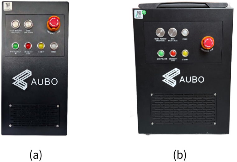
(a) AUBO-CB-iS; (b) AUBO-CB-iS-H
| No. | Description | Function |
|---|---|---|
| 1 | MANIPULATOR ON indicator light | The indicator light comes on when the power supply of the robot body is connected normally. |
| 2 | EMERGENCY STOP indicator light | The indicator light comes on when the robot is in emergency stop state. |
| 3 | STANDBY indicator light | The indicator light comes on when the controller interface board program initialization is completed. |
| 4 | POWER indicator light | The indicator light comes on when the external power supply is connected normally. |
| 5 | TEACH PENDANT ENABLE/DISABLE button | Wired teach pendant enable switch. In the default pop-up state, the wired teach pendant is enabled (teach pendant emergency stop button is valid). If the button is pressed, the teach pendant emergency stop button will be invalid, the wired teach pendant cable can be safely unplugged, and the robot body can be controlled via the interface signal. |
| 6 | MODE MANUAL/LINKAGE button | The robot operating mode can be switched. The robot operates in manual mode by default. If this button is pressed, the robot will enter the linkage mode. |
| 7 | EMERGENCY STOP button | Emergency stop button. Press it to stop the robot immediately. Rotate it in the direction indicated by the button mark to restore the normal operating state. |
4.3.2 Rear Panel
The controller rear panel structure and functions are as shown.
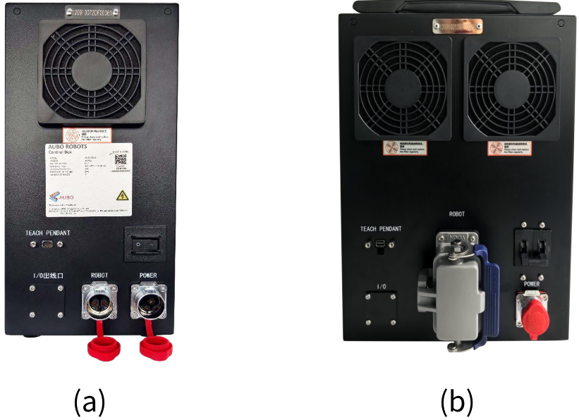
(a) AUBO-CB-iS; (b) AUBO-CB-iS-H
| No. | Description | Function |
|---|---|---|
| 1 | Power switch | Controller power switch. "I" indicates power on, and "O" indicates power off. |
| 2 | POWER interface | Power cable interface, used to connect the power supply. |
| 3 | ROBOT interface | Robot arm cable interface, used to connect the robot arm cable. |
| 4 | TEACH PENDANT interface | Teach pendant cable interface, used to connect the teach pendant cable. |
| 5 | I/O outlet | Controller internal I/O signal outlet. |
4.3.3 Side Panel
Open the controller side panel to view and use the user electrical interface. For detailed interface layout and function description, see Figure 4-4 and Table 4-3.
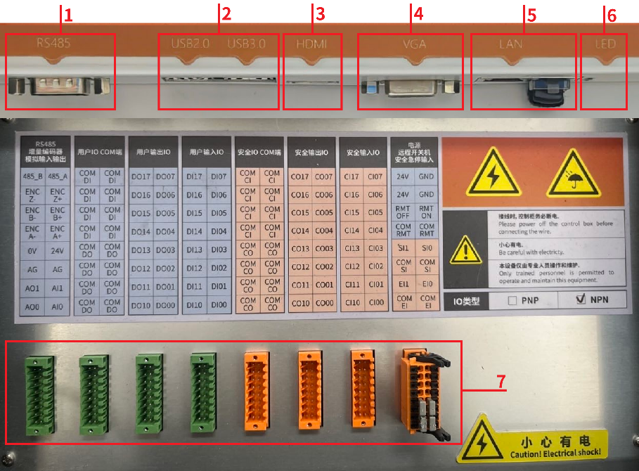
| No. | Description | Function |
|---|---|---|
| 1 | RS485 interface | Supporting Modbus-RTU communication, expanding the number and type of controller I/O interfaces, or adding analog interfaces. |
| 2 | USB2.0, USB3.0 interface | Equipment connection, software upgrade and program file export. |
| 3 | HDMI | Connecting the HDMI of the monitor. |
| 4 | VGA interface | Connecting the VGA interface of the monitor. |
| 5 | LAN outlet | Remote access and control. |
| 6 | LED indicator light | Displaying the operating status of the controller industrial computer. |
| 7 | Terminal interface | External equipment signal connection and system expansion. |
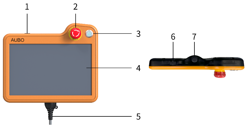
5 Teach Pendant
5.1 Introduction
The AUBO-CB-iS series controller is equipped with the latest ARCS robot operating system independently developed by AUBO, which fully supports both wired and wireless teaching methods. Users can operate the robot arm and controller, execute and create the robot program, and read the robot log information through the dedicated AuboStudio software to meet the requirements of different application scenarios. For specific usage, please refer to the AuboStudio User Manual.
5.2 Wired Teach Pendant
The wired teach pendant is directly connected to the controller through the cable, and the user can use the AuboStudio software on the dedicated equipment for robot control and program development.
| Type | AUBO-TP-iS |
|---|---|
| Dimensions (length * height * width) | 254mm * 213.1mm * 40.8mm |
| Weight | 1.0kg (2.2lbs) (including cable) |
| IP rating | IP54 |
| No. | Description | Function |
|---|---|---|
| 1, 6 | USB interface | Equipment connection, software upgrade and program file export. |
| 2 | Emergency stop button | Quickly stopping the robot in case of emergency. Press and rotate it in the direction indicated on the button to return to normal mode. |
| 3 | System power switch | Controlling the startup and shutdown of the robot system; forced shutdown if necessary. |
| 4 | Touch screen | Displaying the robot operation interface and real-time status information. |
| 5 | Teach pendant cable interface | Connecting the special interface of the controller to ensure the communication between the teach pendant and the control system. |
| 7 | Force control switch | Three-position enable switch, safely controlling the robot teaching operation: OFF (released) => ON => OFF (pressed). When the switch is in the ON state, the robot can be operated safely. |
5.3 Wireless Teaching
If the AUBO-CB-iS series controller is equipped with built-in wireless Wi-Fi, the user can install the AuboStudio Android APP in the tablet to control the robot via the Wi-Fi connection.
6 Installation and Startup
6.1 Robot System Composition
The AUBO robot system is composed of 5 parts: robot arm, controller, carriage, teach pendant, and optional accessories, with a modular design. It meets the diversified application requirements of automation.
Main components and functions of the system:
Robot arm: Execution unit of the system, consisting of multiple joints and links, simulating the kinematic characteristics of the human arm, and realizing precise spatial posture and attitude control.
Controller: Core control body of the system, with built-in robot operating system independently developed by AUBO. A dedicated communication link is established with the robot arm based on real-time CAN bus to coordinate motion control, command execution and system status management.
Carriage: An installation foundation for the robot system to ensure system stability and precise positioning, which can be selected according to the application scenarios.
Teach pendant: A key interface for users to interact with the robot system. It supports both wired (via dedicated cable) and wireless (based on Wi-Fi) teaching methods, providing an intuitive programming, commissioning and system configuration environment to meet different operation requirements.
Optional accessories: Extended function modules such as extended control handle and six-component force sensor to enhance the adaptability and intelligence of the system in specific application scenarios.
The AUBO robot system is highly modular and can be flexibly configured according to user requirements. Figure 6-1 shows a typical system configuration. The actual delivered system may vary slightly depending on the specific application. For the final configuration, please refer to the actual product and technical specification. For the configuration details, consult the AUBO technical support team.
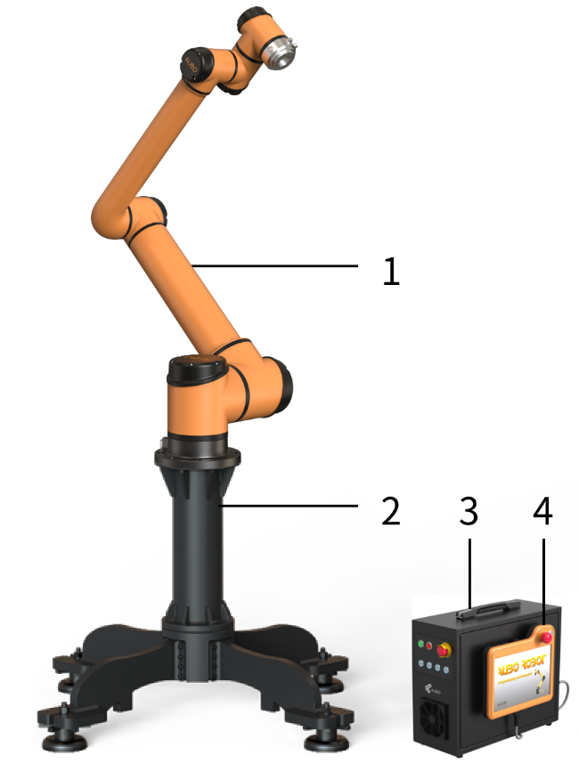
1—Robot arm; 2—Carriage; 3—Control box; 4—Teach pendant
6.2 Important Safety Instructions
| Sign | Description |
|---|---|
| Environmental conditions for installation: 1. No corrosive gas or liquid 2. No oil mist 3. No salt spray 4. No dust or metal powder 5. No mechanical shock or vibration 6. No electromagnetic noise 7. No radioactive materials 8. Low humidity 9. No flammable materials 10. Ambient temperature: 0°C ~ 45°C 11. No direct sunlight (avoiding outdoor use) Instructions for installing additional components: If additional components not covered in the scope of supply of AUBO (Beijing) Intelligent Technology Co., Ltd., such as cables, are integrated into the robot, the user shall ensure that these components have no effect on and will not affect the safety functions. |
| 1. Be sure to carry out a safety assessment after each robot installation, in strict accordance with the instructions in Chapter 3 (Safety). 2. Place the controller horizontally on the ground, and maintain a 50 mm space on each side of the controller to ensure smooth air flow. 3. Hang the teach pendant on the controller if possible, and prevent the cable from being trampled. |
| 1. Make sure that the controller, teach pendant and cable are not exposed to liquids. Do not wet controller, otherwise personal injury or death may be caused. 2. The controller and teach pendant must not be exposed to dusty or humid environment that exceeds the IP rating. Monitor the presence of conductive dust. |
6.3 Cable Connection
The rear panel of the AUBO-CB-iS series controller has 3 interfaces, and the bottom of the robot arm has 1 interface. Before use, the corresponding cables shall be inserted into the interfaces.
| No. | Description | Illustration |
|---|---|---|
| 1 | Robot arm aviation plug cable | 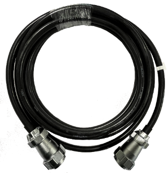 |
| 2 | Power cable | 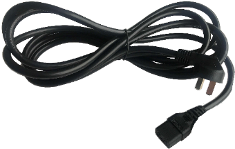 |
| 3 | Connection of controller rear panel interface and cable | 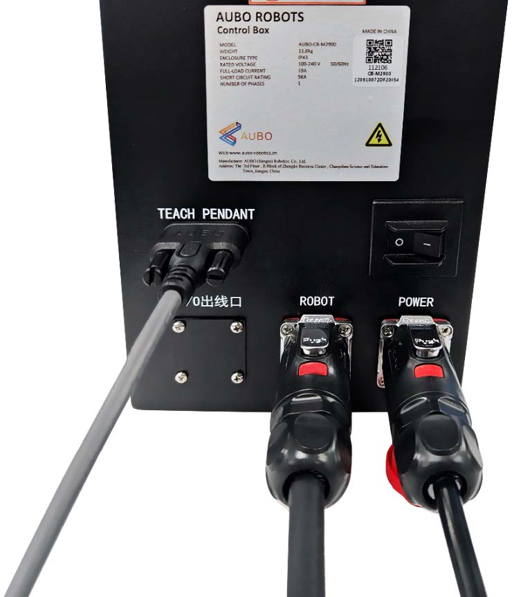 |
| 4 | Connection of robot arm aviation plug cable and robot arm | 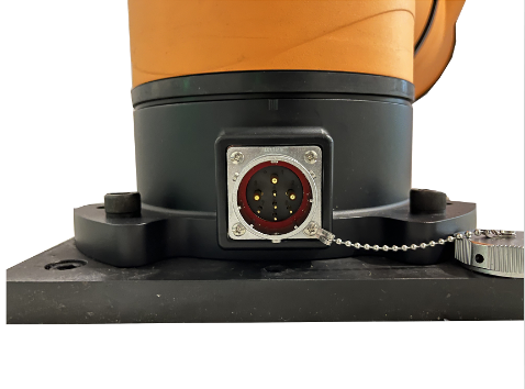 |
| No. | Operation | Description |
|---|---|---|
| 1 | Connection of robot arm aviation plug cable and robot arm | First remove the dust cap of the interface at the bottom of the robot arm. Align the pins of the plug with the socket jack respectively, and align the notch on the socket with the protrusion on the plug. Insert the plug into the socket. Rotate the fastening nut on the plug clockwise (from the plug to the socket) until a "click" sound is heard, indicating successful connection. |
| 2 | Connection of robot arm aviation plug cable and controller | First remove the red dust cap on the controller interface, and then plug the power cable into the ROBOT interface of the controller. Pay attention to the insertion direction, as it will be automatically locked into place. |
| 3 | Connection of wired teach pendant and controller | Insert the cable plug of the wired teach pendant into the TEACH PENDANT interface of the controller, and lock the screws on both sides. |
| 4 | Connection of power cable and controller | First remove the red dust cap on the controller interface, and then plug the power cable into the POWER interface of the controller. Pay attention to the insertion direction, as it will be automatically locked into place. |
| Sign | Description |
|---|---|
| 1. Make sure that the robot is grounded (electrically) in the correct way. The grounded connector shall have a current rating of at least the highest current in the system. 2. Please ensure that all cables are properly connected before the controller is powered on, and use the correct original power cable. |
| 1. Never disconnect the robot power supply when the robot arm is started. 2. Do not extend or modify the original cable. |
6.4 Robot System Power-on
6.4.1 Preparation Before Power-on
Check whether the robot arm is well connected to the controller.
Check whether the wired teach pendant is well connected to the controller.
Check whether the controller power cable is well connected.
The controller power switch is off when the power is not on.
The wired teach pendant emergency stop switch is in the pop-up state.
The MODE MANUAL/LINKAGE button is in the correct position.
Make sure that the robot arm does not collide with surrounding people or equipment.
6.4.2 System Power-on
Power on controller: Press the power switch of the controller from OFF to ON, then the POWER indicator light comes on, and the robot system is powered on.
Power on wired teach pendant and robot arm: Make sure that the MODE MANUAL/LINKAGE button is in the pop-up state. At this time, the robot system is in manual mode, and when the STANDBY indicator light comes on, it indicates that the system enters the standby state. Press and hold the system power switch in the upper right corner of the wired teach pendant for about 1 s, wait for the LED indicator light of the system power switch to light up, then power on the robot and the wired teach pendant together, and the teach pendant screen lights up.
| Sign | Description |
|---|---|
| When the brake of the robot arm is released during power-on, do not intervene in the robot externally, such as assembling/disassembling the tool gripper, shaking the robot, etc. |
6.5 Robot System Shutdown
6.5.1 Normal Shutdown
The normal shutdown methods of AUBO robot system are as follows:
Method 1: Click the [Shutdown] button on the teach pendant software interface.
Method 2: Remote shutdown.
Method 3: Press and hold the system power switch button in the upper right corner of the wired teach pendant for 3 s.
Method 4: Press and hold the on/off button on the control handle for 2 s.
After the normal shutdown of the system, press the power switch of the controller from ON to OFF, and finally unplug the power cable plug connected to the external power supply.
6.5.2 Forced Shutdown
The forced shutdown methods of AUBO robot system are as follows:
Method 1: Press and hold the system power switch button in the upper right corner of the wired teach pendant for 10 s in any state.
Method 2: Press and hold the on/off button on the control handle for 10 s in any state.
Method 3: Cut off the power supply directly.
| Sign | Description |
|---|---|
| 1. The forced shutdown is only allowed under abnormal conditions. 2. Please avoid using forced shutdown. If forced shutdown is required, save the ongoing tasks and files before shutdown if possible, and perform necessary system checks and maintenance afterwards. |
7 Electrical Interfaces
7.1 Introduction
The AUBO-CB-iS series controller provides a variety of electrical interfaces to meet the requirements of different automation application scenarios. The controller integrates video output, communication, and digital/analog signal interfaces, and supports extensive system integration and device interconnection.
For the detailed interface layout, see the side panel in 4.3.3, and for a summary of terminal interfaces, see Table 7-1.
| Interface Type | Classification | Interface Name | Terminal No. | Qty. of interfaces (ways) | Interface specification |
|---|---|---|---|---|---|
| Digital I/O | Fixed function I/O | External safety stop input | SI0, SI1 | 2 | 24VDC |
| Linkage emergency stop input | EI0, EI1 | 2 | 24VDC | ||
| Remote startup | RMT ON | 1 | 24VDC | ||
| Remote shutdown | RMT OFF | 1 | 24VDC | ||
| Configurable I/O (safety) | Digital input | CI00~CI07, CI10~CI17 | 16 | 24VDC | |
| Digital output | CO00~CO07, CO10~CO17 | 16 | 24VDC | ||
| General I/O (user) | Digital input | DI00~DI07, DI10~DI17 | 16 | 24VDC | |
| Digital output | DO00~DO07, DO10~DO17 | 16 | 24VDC | ||
| Analog I/O | General I/O (user) | Analog voltage input | AI0, AI1 | 2 | 0~+10V |
| Analog voltage output | AO0, AO1 | 2 | 0~+10V, 0~20mA | ||
| Communication interface | - | RS485 | 485_A, 485_B | 2 | - |
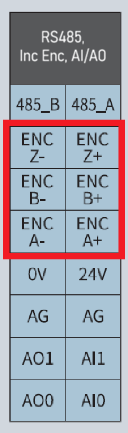
| Encoder interface | - | Incremental encoder | ENC A+, ENC A-, ENC B+, ENC B-, ENC Z+, ENC Z- | 6 | Differential signal |
7.2 Electrical Warnings and Cautions
When designing and installing the robot and AUBO-CB-iS series control boxes applications, as well as performing the maintenance work, be sure to follow the following warnings and cautions.
| Sign | Description |
|---|---|
| 1. Please ensure that all equipment that shall not be exposed to water is kept dry. If water enters the product, cut off the power supply and contact your supplier. 2. Only use the original cable of the robot. Do not use the robot in applications where the cable needs to be bent. If longer cable or flexible cable is required, contact your supplier. 3. All GND connectors mentioned in this document are only applicable to power supply and signal transmission. For protective earthing (PE), use the screw connector marked with the earthing mark in the controller. The grounded connector shall have a current rating of at least the highest current in the system. 4. Be careful when installing the robot I/O interface cable. |
| 1. Never connect safety signals to a non-safety PLC with an inappropriate safety level. Failure to observe this warning may result in serious injury or even death due to the failure of a safety stop function. 2. During the wiring of the controller electrical interfaces, the controller must be powered off. |
 | 1. Interference signals above the level specified in the IEC standard will cause abnormal behavior of the robot. High or excessive exposure to this signal level will cause permanent damage to the robot. EMC problems usually occur during welding and are usually indicated by error messages in the log. AUBO (Beijing) Intelligent Technology Co., Ltd. shall not be liable for any loss caused by EMC problems. 2. The length of I/O cable used to connect the controller to other machinery and equipment shall not exceed 30 m, unless extended testing demonstrates feasibility. |
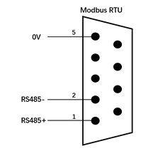
7.3 Communication Interface
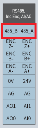
7.3.1 RS485 Interface
The AUBO-CB-iS series control box has a standard RS485 interface, which can be used to connect Modbus devices. The pin description is as shown.
7.3.2 USB Interface
The AUBO-CB-iS series controller provides two standard interfaces of USB2.0 and USB3.0, which can be used for equipment connection, software upgrade and program file export.
7.3.3 LAN Interface
The AUBO-CB-iS series controller is equipped with industrial-grade wired Ethernet interface as standard, providing efficient and stable network communication capabilities for robot system, and supporting remote access and control.
7.4 I/O Control Mode
7.4.1 Signal Level Control
The AUBO-CB-iS series control box provides NPN and PNP level control modes, which are preset and marked at the factory, as shown in Figure 7-2.
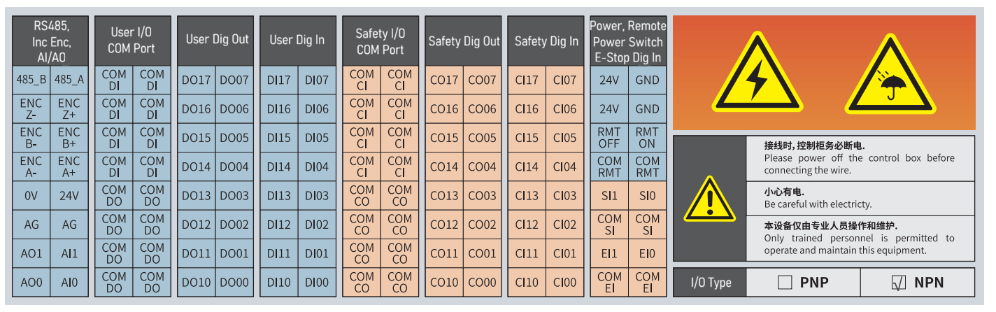
| Sign | Description |
|---|---|
| The level control mode of the controller is professionally configured at the factory. Users must not modify it without authorization to ensure the stability and safety of the system. |
7.4.2 COM Port
The AUBO-CB-iS(CE) and AUBO-CB-iS-H controllers adopt modular COM port architecture and provide refined signal management solutions, as shown in Figure 7-3. The COM port can be divided into two types: input and output types according to signal direction and function attributes. Detailed functions and instructions are as shown in Table 7-2.
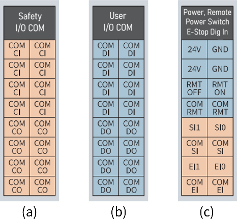
| COM Port | Function | Qty. | Instructions | |
|---|---|---|---|---|
| Input COM | COM SI | External safety stop input common port | 2 | Used in conjunction with external safety stop input |
| COM EI | Linkage emergency stop input common port | 2 | Used in conjunction with linkage emergency stop input | |
| COM RMT | Remote power-on/off input common port | 2 | Used in conjunction with remote power-on/off input | |
| COM CI | Configurable I/O input common port | 8 | Used in conjunction with configurable I/O input | |
| COM DI | General I/O input common port | 8 | Used in conjunction with common I/O input | |
| Output COM | COM CO | Configurable I/O output common port | 8 | Used in conjunction with configurable I/O output |
| COM DO | General I/O output common port | 8 | Used in conjunction with general I/O output | |
| Sign | Description |
|---|---|
| 1. The I/O valid level mode is pre-configured at the factory, and the user shall carefully check the I/O type mark inside the controller. 2. Whether NPN or PNP signal level control is used, the valid level of the input and output shall follow the factory preset configuration. 3. Under both NPN and PNP signal level control, the COM port shall be consistent with I/O wiring principles. |
7.5 I/O Power Supply
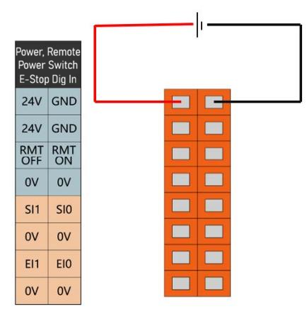
7.5.1 Internal Power Supply
The controller panel I/O defaults to internal power supply mode, as shown in Figure 7-4.
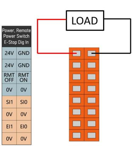
7.5.2 External Power Supply
If the user needs to use an external power supply, please refer to the methods shown in Figure 7-5.
7.6 Fixed Function I/O
7.6.1 Fixed Safety Stop Input
The AUBO-CB-iS series controller provides two fixed safety stop inputs:
External safety stop input (SI0, SI1): For safety-type protection devices.
Linkage emergency stop input (EI0, EI1): Only for emergency stop devices, realizing multi-machine linkage emergency stop.
The function differences between these two are as shown in Table 7-3.
| External safety stop input | Linkage emergency stop input | |
|---|---|---|
| Robot motion stop | Yes | Yes |
| Program execution | Pause | Stop |
| Robot power supply | ON | OFF |
| Reset | Automatic or manual | Manual |
| Operating frequency | Not more than once per operating cycle | Infrequently used |
| Re-initialization required | No | Release brake only |
| Stop category | 2 | 1 |
| Safety input function | Extreme case | ||
|---|---|---|---|
| Detection time | Power-off time | Response time | |
| External safety stop input | 100ms | 1200ms | 1300ms |
| Linkage emergency stop input | 100ms | - | 1200ms |
7.6.2 Remote Startup/Shutdown
When the system is in manual mode, the robot system can be powered on or off by using the remote power-on/off control I/O interface.
| Input | Function definition |
|---|---|
| RMT ON | Remote power-on signal input interface |
| RMT OFF | Remote power-off signal input interface |
7.7 Controller Configurable I/O
The AUBO-CB-iS series controller provides 16 configurable DI interfaces and 16 configurable DO interfaces. It adopts a dual-circuit safety channel design, which can ensure that the system maintains safety functions in case of a single fault.
The configurable I/O can only be used as safety I/O after it is configured in teach pendant software. If it is not configured, the default is general digital I/O. Safety I/O always has the highest priority. When the same I/O port is configured with both safety I/O and general I/O functions, the system will give priority to the safety I/O function. For detailed functions and instructions on the safety I/O, please refer to the AuboStudio User Manual.
When configurable I/O is used as safety I/O, strict safety guidelines must be followed. Before use, all safety devices and related equipment must be installed in accordance with professional safety instructions and undergo a comprehensive risk assessment.
| Input/output | Function definition |
|---|---|
| CI00~CI07 | Set the specific functions on the software interface |
| CI10~CI17 | |
| CO00~CO07 | |
| CO10~CO17 |
7.8 Controller General I/O
7.8.1 Function Definition
The AUBO-CB-iS series controller provides 16(+16) DI interfaces, 16(+16) DO interfaces, 2 analog voltage input interfaces and 2 analog voltage output interfaces.
The specific functions of the general I/O need to be configured in the teach pendant software. For detailed function description and configuration methods, please refer to the AuboStudio User Manual.
| Input/output | Function definition |
|---|---|
| DI00~DI07 | Set the specific functions on the software interface |
| DI10~DI17 | |
| DO00~DO07 | |
| DO10~DO17 | |
| AI0, AI1 | |
| AO0, AO1 |
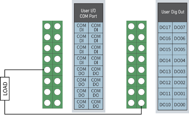
7.8.2 General Digital I/O Interface
The AUBO-CB-iS series control boxes provides flexible I/O signal level control scheme.
| Input/Output | Parameter | Parameter |
|---|---|---|
| DI | Input signal form | Input signal form |
| Input mode | Input mode | |
| Electrical specifications | Electrical specifications | |
| DO | Output signal form | Output signal form |
| Electrical specifications | Electrical specifications |
Example
- DI interface button switch
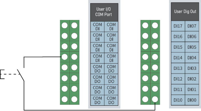
- DO interface load
7.8.3 General Analog I/O Interface
The analog I/O interface is located in the leftmost row of terminal interfaces on the controller side panel. It has 2 analog voltage inputs and 2 analog voltage outputs, which are represented by AI and AO respectively, as shown in Figure 7-8.
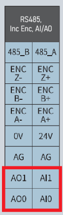
| Type | Voltage |
|---|---|
| Input | 0 ~ +10V |
| Output | 0 ~ +10V |
| Accuracy | ±1% |
| Parameter | Minimum | Maximum | Unit |
|---|---|---|---|
| Input voltage | 0 | +10 | V |
| Input resistance | 100K | Ω | |
| AI sampling resolution | 12 | BITS | |
| AI sampling accuracy | 10 | BITS | |
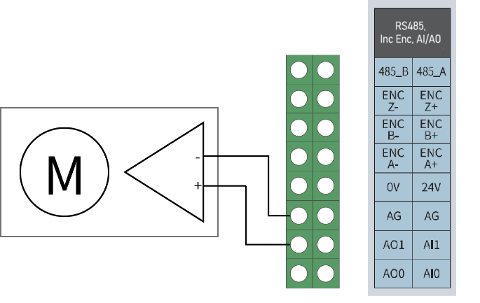
Example
- Wiring methods for analog voltage input
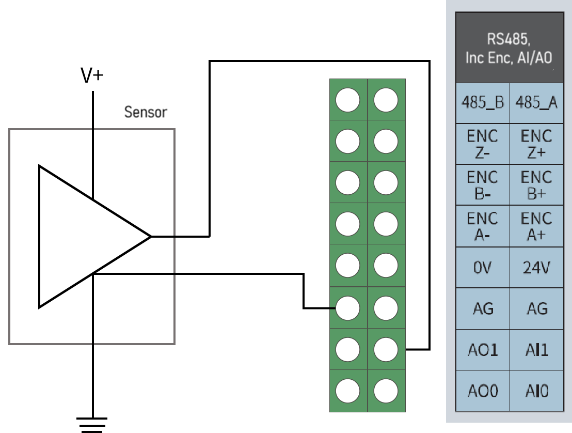
- Wiring method for analog voltage output
7.9 Terminal Block RS485 Interface
The RS485 interface in the terminal block is as shown in Figure 7-11 and can be used for Modbus RTU communication.
7.10 Incremental Encoder Interface
The incremental encoder interface is as shown in Figure 7-12, and some peripherals can be connected.
8 Handling and Precautions
When hoisting the robot, secure the moving parts by appropriate measures to prevent accidental movement during hoisting and transportation, which will cause unexpected damage. During packaging for transportation, carry out the packaging according to the packaging standard, and make marks on the outside of the packaging box as required.
During transportation, ensure that the robot is stable and fixed in a proper position.
Lift the controller with a handle.
When moving the robot from the robot packaging material to the installation position, hold the robot until all the bolts of the robot base are tightened.
After fixing, power on the robot, and adjust the robot attitude as appropriate using the HandGuide function.
Keep the original packaging after transportation. Store the packaging material in a dry place for future use when the robot needs to be repacked and transferred.
| Sign | Description |
|---|---|
| 1. Make sure that your back or other body parts are not overloaded when lifting the equipment. 2. Follow all regional and national guidelines. AUBO (Beijing) Intelligent Technology Co., Ltd. shall not be responsible for any damage arising from improper transportation. 3. Make sure that the robot is installed in strict accordance with the installation instructions in the manual. |
9 Maintenance
Maintenance operations must be done in strict accordance with all safety instructions herein.
The maintenance, calibration and repair work must be performed according to the latest service manual, which is available on the website: www.aubo-robotics.cn. All dealers of AUBO (Beijing) Intelligent Technology Co., Ltd. are authorized to access this website.
Maintenance must be carried out by an authorized system integrator or AUBO (Beijing) Intelligent Technology Co., Ltd. Parts shall be returned to AUBO (Beijing) Intelligent Technology Co., Ltd. in accordance with the instructions in service manual.
The maintenance must be carried out with the specified safety level secured and according to the currently effective national or regional work safety regulations, and all safety functions shall be tested for normal working.
The maintenance is intended to secure the normal operation of the system or to recover a faulty system to normal. Maintenance includes fault diagnosis and repair.
The following safety procedures and precautions must be followed to operate the robot arm or controller:
| Sign | Description |
|---|---|
| 1. Disconnect the main input cable from the back of the controller to ensure that it is completely powered off. Take necessary measures to prevent authorized personnel from re-connecting the power supply to the system during maintenance. After the power supply is cut off, check the system again to ensure that it is powered off. 2. Check the ground connection before restarting the system. 3. Follow the ESD (electrostatic discharge) regulations when disassembling the robot arm or controller. 4. Avoid disassembling the power supply system of the controller. Pay attention that the power supply system of the controller will remain at high voltage for several hours after the controller is turned off. 5. Prevent water or dust from entering the robot arm or controller. |
10 Disposal
AUBO robot must be disposed of in accordance with applicable national laws and regulations and national standards.
11 Warranty
11.1 Warranty
AUBO robots feature a limited warranty period of 18 months.
If the new equipment or any of its component exhibits defects resulting from poor manufacturing and/or material within 18 months from the start of use, AUBO (Beijing) Intelligent Technology Co., Ltd. shall provide the necessary spare parts for replacement or repair.
AUBO (Beijing) Intelligent Technology Co., Ltd. has the ownership of the equipment or components replaced or returned to the AUBO (Beijing) Intelligent Technology Co., Ltd.
When the warranty expires, AUBO (Beijing) Intelligent Technology Co., Ltd. reserves the right to charge the customer for replacement or repair.
If the equipment is defective outside the warranty period, AUBO (Beijing) Intelligent Technology Co., Ltd. shall not be liable for any damage or loss arising therefrom, such as production loss or damage to other production equipment.
11.2 Disclaimer
The warranty will be invalid if the defect is caused by improper handling or failure to follow the relevant information in the User Manual.
Faults caused by the following conditions are not covered by this warranty:
Purchase of products through channels not approved by AUBO;
Failure to perform installation, wiring and connection of other control device in accordance with industrial standards or the requirements in the User Manual;
Use of this product beyond the nominal specifications or standards;
Use of this product for purposes other than those specified;
Use of this product in environmental conditions out of the nominal settings;
Use of this product in a grinding environment or a special use environment without protection;
Product damage due to improper transportation;
Failure, damage or consequential damage caused by accidents or human factors;
Failure, damage or consequential damage caused by modification;
Use of non-genuine parts and accessories;
Damage caused by modification, commissioning or repair of original parts by a third party other than AUBO (Beijing) Intelligent Technology Co., Ltd. or its designated integrator;
Failure, damage or consequential damage caused by natural disasters or other force majeure;
Faults not related to the responsibility of AUBO (Beijing) Intelligent Technology Co., Ltd., apart from those mentioned above.
Warranty will not be provided in following circumstances:
Failure to identify product traceability number.
Failure to identify the date of manufacture or the warranty start date.
Changes to software or internal data.
Failure to reproduce the fault or failure to identify the fault by AUBO (Beijing) Intelligent Technology Co., Ltd.
Use of this product in radioactive equipment, biological test equipment or in other dangerous applications ascertained by AUBO (Beijing) Intelligent Technology Co., Ltd.
Appearance parts and wearing parts.
According to the warranty agreement, AUBO (Beijing) Intelligent Technology Co., Ltd. will only provide warranty services for defects and deficiencies of the products and parts sold to dealers.
AUBO (Beijing) Intelligent Technology Co., Ltd. shall not be liable for any other express or implied warranties or liabilities, including but not limited to any implied warranties for merchantability or fitness for a specific use. In addition, AUBO (Beijing) Intelligent Technology Co., Ltd. shall not be liable for any indirect damage or consequences of any kind arising from the relevant products.
12 Appendix A Glossary
Category 0 stop: Robot motion is stopped by immediate removal of power to the robot. This is an uncontrolled stop, where the robot may deviate from the programmed path because each joint brakes as fast as possible. This protective stop is used if the safety assessment limit is exceeded or in case of a fault in the safety-related parts of the control system. For more information, see EN ISO 13850:2008 or IEC60204-1:2006.
Category 1 stop: Robot motion is stopped with power available to the robot and then the power is removed when the stop is achieved. It is a controlled stop, where the robot will continue moving along the programmed path. Power is removed after one second or as soon as the robot stands still. For more information, see EN ISO 13850:2008 or IEC60204-1:2006.
Category 2 stop: Category 2 stop is a controlled stop with power left available to the robot. The robot stops all motions within one second. The safety-related control system monitors that the robot stays at the stop position. For more information, see IEC60204-1:2006.
Diagnostic coverage (DC): Diagnostic coverage is a measure of the effectiveness of the diagnostics implemented to achieve the rated performance level. For more information, see EN ISO 13849-1:2008.
Integrator: The integrator is the entity that designs the final robot installation, which is responsible for performing final risk assessment and must ensure that the final installation of robot complies with local laws and regulations.
Mean Time to Dangerous Failure (MTTFd): Mean Time to Dangerous Failure (MTTFd) is a value based on calculations and tests used to achieve the rated performance level. For more information, see EN ISO 13849-1:2008.
Risk assessment: A risk assessment is the overall process of identifying all risks and reducing them to an appropriate level. A risk assessment should be documented. For more information, see ISO 12100.
Performance level: Performance level (PL) is a discrete level used to specify the ability of safety-related parts of control system to perform a safety function under foreseeable conditions. PLd is the second highest reliability classification, meaning that the safety function is extremely reliable. For more information, see EN ISO 13849-1:2008.