CB-G40-Mini Series Control Box User Manual
1 About this Manual
1.1 Version information
V1.0.0
The User Manual will be regularly checked and corrected, and the updates will be incorporated in the new version. The information in this manual is subject to change without notice.
AUBO (Beijing) Intelligent Technology Co., Ltd. shall not be liable for any errors or omissions in this Manual, or for any accidental or consequential injuries arising from the use of this Manual and the products described therein.
Please read this manual before installing and using the product described herein.
Please keep this manual for the convenience of reading or reference when necessary.
All pictures in this manual are for reference only and the product received serves as the standard.
This Manual is the exclusive property of AUBO (Beijing) Intelligent Technology Co., Ltd. and may not be copied, reproduced in whole or in part, or converted into any other form for use without the written permission of AUBO (Beijing) Intelligent Technology Co., Ltd.
Copyright © 2015-2026 AUBO All rights reserved.
2 Revision
| Version / Time | Description |
|---|---|
| v1.0.0* / 20260626 | v1.0.0* (Trial) released. |
3 Safety
3.1 Introduction
Integrators and users must read this Manual carefully, especially the content with warning signs, which must be mastered and strictly observed. Industrial robot system is complex and potentially dangerous. Users must have a comprehensive safety awareness, deeply understand the possible risks in the operation process, and strictly abide by the industrial robot safety requirements in ISO 10218.
3.2 Warning Signs
The safety-related content in this Manual are indicated by the following warning signs. The content indicated by warning signs in this Manual represent important reminders for personal safety and equipment safety, and users must fully understand and strictly follow them.
| Sign | Description |
|---|---|
 | It indicates a possibly hazardous situation that, if not avoided, could result in death or serious injury. |
 | It indicates a possibly hazardous situation, if not avoided, could result in injury to personnel or major damage to equipment. |
 | It indicates a possibly hazardous situation, if not avoided, could result in injury to personnel or damage to equipment. Attention shall be paid that the hazards indicated by this sign may sometimes cause more significant consequences, depending on the specific circumstances. |
 | It indicates a situation that, if not avoided, could result in injury to personnel or damage to equipment. Attention shall be paid that the hazards indicated by this sign may sometimes cause more significant consequences, depending on the specific circumstances. |
3.3 Safety Precautions
3.3.1 Instructions for Use
When starting the device for the first time, be sure to read and follow the basic safety information in this manual. Other detailed safety instructions are provided in subsequent sections of the manual. However, as a wide range of scenarios may arise during actual operation, this manual cannot cover all prohibited or inadvisable operations.
| Sign | Description |
|---|---|
| 1. Always install the machine and all electrical equipment in accordance with the requirements and specifications herein. 2. Make sure to perform a preliminary test and inspection of the machine and its protection system before using the robot or putting it into production for the first time. 3. Before starting the robot or robot system for the first time, check whether the robot or robot system is in good condition and safe for operation, without any damage detected; and test, with all safety functions covered, whether the currently effective national or local safety production rules and regulations are satisfied. 4. Always check that all safety parameters and user programs are correct and that all safety functions are working properly, which must be done by personnel qualified to operate the robot. Do not start the robot until it has passed the thorough safety test, proving that it reaches the specified safety level. 5. Always get the installation and commissioning performed by professionals according to the installation standards. 6. When the robot is installed, carry out a comprehensive risk assessment again and keep a record therefor. 7. Always get the setting and modification of safety parameters carried out by authorized personnel, and apply security measures such as password or isolation measure to prevent their unauthorized modification or setting. After the safety factor is modified, be sure to analyze the relevant safety functions. 8. In case of an accident or abnormal operation, press down the emergency stop button to stop the robot if necessary. 9. Each joint module of the AUBO series robot is equipped with a brake to maintain the robot posture during power failure. Do not manually switch the power supply system on and off frequently. It is recommended that the time interval between each power-on and power-off operation be more than 10 seconds. 10. The AUBO series robot is equipped with a collision detection function. When an external force applied to the powered-on robot exceeds the normal force range set by the user for safety, the robot will stop automatically to prevent collision injuries to the robot itself or operators. This function is specially designed to ensure safety during human-robot collaborative work for AUBO series robots, provided that the robot system operates within its normal working range and uses an original AUBO series controller. If users develop their own custom controllers, the robot will not support the above function, and users shall bear all hazardous consequences arising therefrom. 11. The controller generates heat during operation. Do not operate or touch the robot when it is working or immediately after it stops. Instead, cut off the power supply and wait for an hour until the robot cools down. 12. Do not put your fingers in the heating part of the controller. |
| 1. Ensure that the machine is correctly and safely installed in place. 2. Ensure sufficient clearance space for free movement of the robot arm. 3. Stop using the robot when it is damaged. 4. Do not connect safety devices to general-purpose I/O interfaces, and instead, please use safety-related interfaces only. 5. Ensure correct installation setup (such as mounting angle of robot body, payload weight in TCP, TCP offset, and safety configuration). Save the installation file and load it into the program. 6. Tools and obstacles shall be free of sharp corners or jagged edges. Ensure that the heads and faces of all personnel stay outside the robot's reachable workspace. 7. Ensure the correct installation and settings. 8. Unregulated movements will release substantial kinetic energy, which can easily generate impact forces when interacting with high-speed payloads. 9. Since connection of different machines may increase the risk or lead to new dangers, always perform a comprehensive risk assessment for the entire installation. When different safety and emergency shutdown performance levels are required, always select the highest one. Always read and understand the manuals of all equipment used in the installation. 10. Do not modify the robot, as any changes to the robot may cause unpredictable danger to the integrator. Carry out robot restructuring with authorization and according to the latest version of all relevant service manuals. If the robot is changed or altered in any way, AUBO (Beijing) Intelligent Technology Co., Ltd. disclaims all liability. 11. Before transporting the robot, check the insulation and protection measures. 12. Follow the transportation requirements when transporting the robot, and handle it carefully to avoid bumps. |
| 1. When the robot is combined with or working together with other machine that can cause robot damage, it is strongly recommended to check all functions of the robot separately. 2. AUBO (Beijing) Intelligent Technology Co., Ltd. shall not be liable for any robot damage or personal injury caused by improper operation. 3. Do not expose the robot to a permanent magnetic field, as strong magnetic fields can damage the robot. |
3.3.2 Operator Safety
Operator safety is the first consideration that must be secured during the operation of the robot system. The general precautions are listed in the table below, and appropriate measures shall be taken to ensure the safety of operators.
| Sign | Description |
|---|---|
| 1. Each operator using the robot system shall be trained through the training courses hosted by AUBO (Beijing) Intelligent Technology Co., Ltd. Users shall fully grasp the safe and standardized operating procedures with the robot operating qualifications. Please inquire for training details via email support@aubo-robotics.cn. 2. Do not wear loose clothes or jewelry when working with the robot systems, and make sure long hair is combed up at the back of the head. 3. When the robot is running, even if it appears to have stopped, it is possible that the robot is waiting for a start signal and in the state of imminent action, and even in such state, the robot should be considered as being in motion. 4. In emergency and abnormal situations, for example, when an operator is caught in or surrounded by a robot, push or pull the robot arm with force to force the joint to move. Manual movement of the robot arm without electric drive is for emergency use only, and may cause damage to the robot arm joint. |
3.4 Responsibilities and Regulations
The AUBO-G40 series controller can be combined with other equipment to form a complete machine and itself is not complete. Therefore, this Manual does not cover the instructions on how to design, install and operate a complete robot, nor does it cover all peripheral equipment that can influence the safety of the complete system. The safety of a complete robot installation depends on its integration. The integrator shall conduct risk assessment on the design and installation of the complete system in accordance with laws, regulations, safety codes and standards where the robot is installed. Risk assessment is one of the most important tasks that an integrator must be done. Guidance on the risk assessment process may be found in the following standards.
ISO 12100:2010 Safety of Machinery - General Principles for Design - Risk Assessment and Risk Reduction;
ISO 10218-2:2025 Robots and Robotic Devices - Safety Requirements for Industrial Robots - Part 2: Robot Systems and Integration;
RIA TR R15.306-2014 Technical Report - Industrial Robots and Robot Systems - Safety Requirements - Task-based Risk Assessment Methodology;
ANSI B11.0-2010 Safety of Machinery; General Requirements and Risk Assessment;
The responsibilities to be fulfilled by an integrator include but are not limited to:
comprehensive risk assessment of complete robot system;
confirmation of the correctness of the system's design and installation;
provision of training to users and staff;
development of the operation specification of the complete system with specific operation process defined;
development of appropriate safety measures;
adoption of appropriate methods to eliminate hazards or minimize any hazards to an acceptable level at the time of final installation;
communication of residual risks to end users;
marking of the integrator's logo and contact information on the robot;
archiving of relevant technical documents.
For applicable standards and laws, please visit: www.aubo-robotics.cn.
All safety information contained herein shall not be regarded as a guarantee from AUBO (Beijing) Intelligent Technology Co., Ltd. It should be understood that, even if all safety instructions referred to herein are observed, personal injury or equipment damage is still likely to occur.
AUBO (Beijing) Intelligent Technology Co., Ltd. is committed to continuously improving the reliability and performance of its products, and therefore reserves the right to upgrade products without notice. AUBO (Beijing) Intelligent Technology Co., Ltd. will make every possible effort to ensure the accuracy and reliability of the information in this manual, but shall not be liable for any errors or omissions therein.
3.5 Hazard Identification
Risk assessment shall account for all potential contact scenarios between operators and the robot during normal operation, along with foreseeable misoperations. The operator's neck, face and head shall be kept covered to avoid impact contact. If the robot is to be operated without peripheral safety guarding devices, a risk assessment must first be performed to judge whether relevant hazards will lead to unacceptable risks, such as:
The use of sharp end effectors or tool connectors may present hazards;
Handling toxic or other harmful substances may present hazards;
Operators' fingers face pinching risks from the robot base or joints;
Hazards caused by collisions with the robot;
Hazards stemming from insufficient fixation of the robot or end-mounted tools;
Hazards generated by impacts between the robot payload and rigid surfaces.
The integrator shall evaluate such hazards and their corresponding risk grades through risk assessment, then define and implement matching countermeasures to reduce risks down to an acceptable level. Please note that individual robot units may have other significant unlisted hazards.
By combining the inherent safety design measures built into AUBO robots with safety protocols and risk assessments executed by integrators and end users, risks linked to collaborative operation of AUBO series robots shall be minimized to the lowest reasonably practicable extent. This document relays all residual risks of the robot (prior to installation) to integrators and end users. If an integrator's risk assessment identifies hazards within a specific application that would expose users to unacceptable risks, the integrator must deploy suitable risk-reduction measures to eliminate or greatly mitigate those hazards until risks reach an acceptable threshold. Operation is unsafe until adequate risk-reduction measures (where applicable) are put in place.
For non-collaborative robot installations (for instance, when hazardous tools are deployed), risk assessment may determine that the integrator must wire in extra safety hardware (such as safe-start devices) during programming to safeguard personnel and equipment.
3.6 Emergency Response
3.6.1 Emergency Stop Device
Pressing the emergency stop button will immediately stop all motions of the robot. Emergency stop is not intended as a risk reduction measure, but as a secondary protection device. When multiple emergency stop buttons are to be connected, they must be included in the risk assessment of robot application. The emergency stop button meets the requirements of IEC 60947-5-5.
The controller is also equipped with an external emergency stop button interface (as shown), which can be used by the integrator or user according to the actual situation.
| Sign | Description |
|---|---|
| Tooling or equipment connected to the end of the robot arm must be integrated into the emergency stop circuit of the system if they pose a potential threat. Failure to comply with this warning may result in death, serious personal injury or major property damage. |
3.6.2 Recovery from Emergency Stop State
All emergency stop devices designed in the form of a button feature a "lock", which must be unlocked to end the emergency stop state.
The "lock" can be unlocked by rotating the emergency stop button.
| Sign | Description |
|---|---|
| Recovering from the emergency stop state is a simple but very important step, which can be operated only when the danger of the robot system is confirmed to be completely eliminated. |
4 Handling and Precautions
When packaging for transportation, package the robot in compliance with packaging standards and make required markings on the outer side of the packaging box. During transportation, ensure the robot stays stable and firmly fixed in a proper position.
Lift the controller by its handle. When hoisting the robot, adopt proper measures to secure moving parts, so as to prevent unexpected movement during hoisting and transportation that may cause damage.
Transfer the robot from packaging materials to the installation position. Power on the robot after complete fixation and verify its normal operating status.
Keep the original packaging intact after transportation. Store packaging materials in a dry area for future repacking and robot relocation as needed.
| Sign | Description |
|---|---|
| 1. Make sure that your back or other body parts are not overloaded when lifting the equipment. 2. Follow all regional and national guidelines. AUBO (Beijing) Intelligent Technology Co., Ltd. shall not be responsible for any damage arising from improper transportation. 3. Make sure that the robot is installed in strict accordance with the installation instructions in the manual. |
5 Maintenance And Disposal
5.1 Maintenance
Maintenance operations must be done in strict accordance with all safety instructions herein.
The maintenance, calibration and repair work must be performed according to the latest service manual, which is available on the website: www.aubo-robotics.cn. All dealers of AUBO (Beijing) Intelligent Technology Co., Ltd. are authorized to access this website.
Maintenance must be carried out by an authorized system integrator or AUBO (Beijing) Intelligent Technology Co., Ltd. Parts shall be returned to AUBO (Beijing) Intelligent Technology Co., Ltd. in accordance with the instructions in service manual.
The maintenance must be carried out with the specified safety level secured and according to the currently effective national or regional work safety regulations, and all safety functions shall be tested for normal working.
The maintenance is intended to secure the normal operation of the system or to recover a faulty system to normal. Maintenance includes fault diagnosis and repair.
The following safety procedures and precautions must be followed to operate the robot arm or controller:
| Sign | Description |
|---|---|
| 1. Disconnect the main input cable from the back of the controller to ensure that it is completely powered off. Take necessary measures to prevent authorized personnel from re-connecting the power supply to the system during maintenance. After the power supply is cut off, check the system again to ensure that it is powered off. 2. Check the ground connection before restarting the system. 3. Follow the ESD (electrostatic discharge) regulations when disassembling the robot arm or controller. 4. Avoid disassembling the power supply system of the controller. Pay attention that the power supply system of the controller will remain at high voltage for several hours after the controller is turned off. 5. Prevent water or dust from entering the robot arm or controller. |
5.2 Disposal
AUBO robot must be disposed of in accordance with applicable national laws and regulations and national standards.
6 Warranty
6.1 Warranty
CB-G40-Mini Controller features a limited warranty period of 18 months.
If the new equipment or any of its component exhibits defects resulting from poor manufacturing and/or material within 18 months from the start of use, AUBO (Beijing) Intelligent Technology Co., Ltd. shall provide the necessary spare parts for replacement or repair.
AUBO (Beijing) Intelligent Technology Co., Ltd. has the ownership of the equipment or components replaced or returned to the AUBO (Beijing) Intelligent Technology Co., Ltd.
When the warranty expires, AUBO (Beijing) Intelligent Technology Co., Ltd. reserves the right to charge the customer for replacement or repair.
If the equipment is defective outside the warranty period, AUBO (Beijing) Intelligent Technology Co., Ltd. shall not be liable for any damage or loss arising therefrom, such as production loss or damage to other production equipment.
6.2 Disclaimer
The warranty will be invalid if the defect is caused by improper handling or failure to follow the relevant information in the User Manual.
Faults caused by the following conditions are not covered by this warranty:
Purchase of products through channels not approved by AUBO;
Failure to perform installation, wiring and connection of other control device in accordance with industrial standards or the requirements in the User Manual;
Use of this product beyond the nominal specifications or standards;
Use of this product for purposes other than those specified;
Use of this product in environmental conditions out of the nominal settings;
Use of this product in a grinding environment or a special use environment without protection;
Product damage due to improper transportation;
Failure, damage or consequential damage caused by accidents or human factors;
Failure, damage or consequential damage caused by modification;
Use of non-genuine parts and accessories;
Damage caused by modification, commissioning or repair of original parts by a third party other than AUBO (Beijing) Intelligent Technology Co., Ltd. or its designated integrator;
Failure, damage or consequential damage caused by natural disasters or other force majeure;
Faults not related to the responsibility of AUBO (Beijing) Intelligent Technology Co., Ltd., apart from those mentioned above.
Warranty will not be provided in following circumstances:
Failure to identify product traceability number.
Failure to identify the date of manufacture or the warranty start date.
Changes to software or internal data.
Failure to reproduce the fault or failure to identify the fault by AUBO (Beijing) Intelligent Technology Co., Ltd.
Use of this product in radioactive equipment, biological test equipment or in other dangerous applications ascertained by AUBO (Beijing) Intelligent Technology Co., Ltd.
Appearance parts and wearing parts.
According to the warranty agreement, AUBO (Beijing) Intelligent Technology Co., Ltd. will only provide warranty services for defects and deficiencies of the products and parts sold to dealers.
AUBO (Beijing) Intelligent Technology Co., Ltd. shall not be liable for any other express or implied warranties or liabilities, including but not limited to any implied warranties for merchantability or fitness for a specific use. In addition, AUBO (Beijing) Intelligent Technology Co., Ltd. shall not be liable for any indirect damage or consequences of any kind arising from the relevant products.
7 Use of the Controller
7.1 Introduction
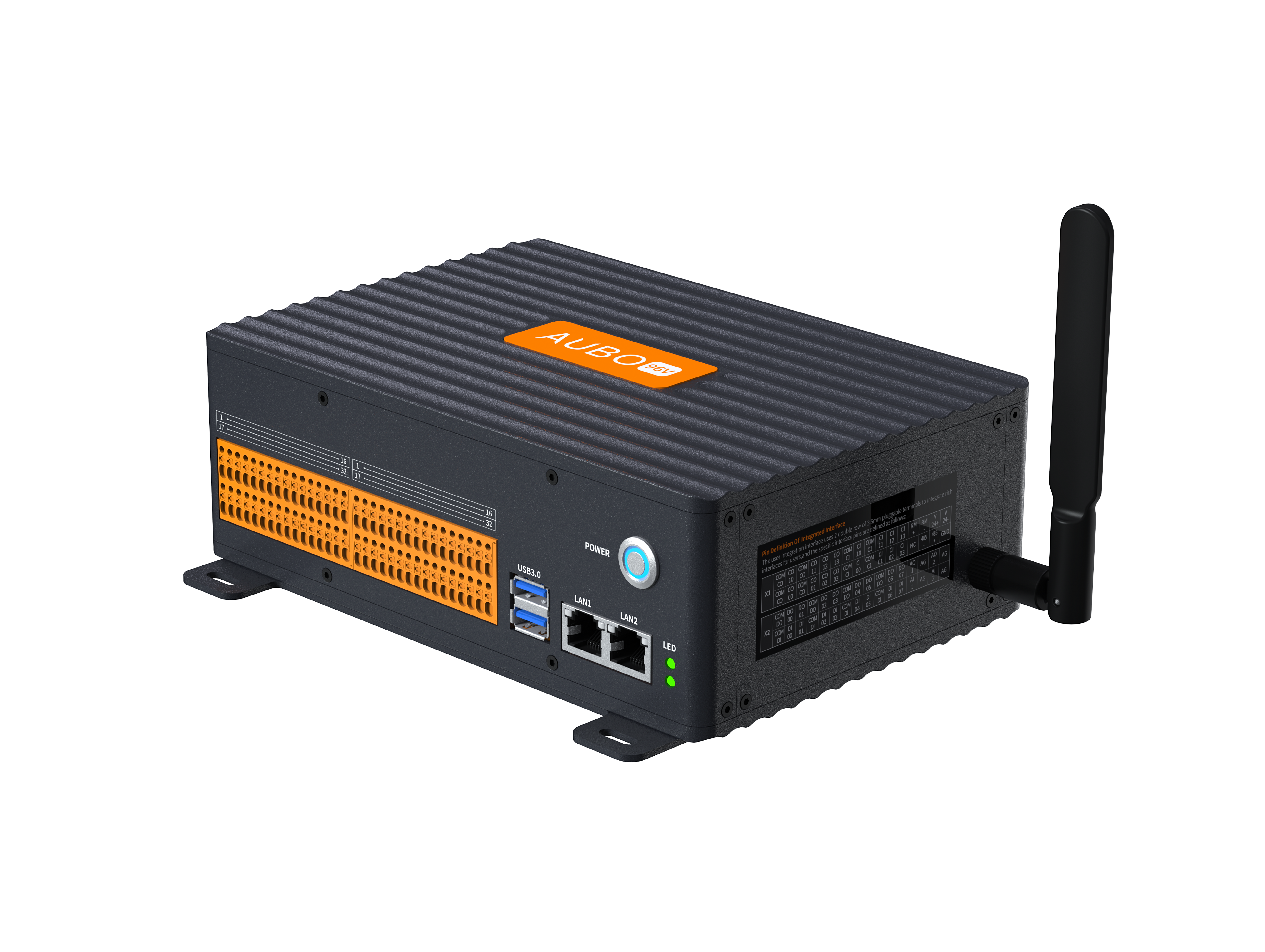
The CB-G40-Mini, a compact controller of the G series, is a tailor-made product developed by Aubo for lightweight, mobile operation, space-limited and embedded integration scenarios. Featuring an ultra-small footprint, the complete unit measures merely 234×169×69.9 mm and weighs 8 kg. Despite its compact size, it can drive high-load robotic arms. It supports matching with the self-developed G-STICK handle kit.
7.2 Safety Instructions
| Sign | Description |
|---|---|
| 1. The cabinet contains hazardous 220V AC and 96V DC voltages. Only qualified professionals are allowed to open the cabinet while power is on. 2. Do not directly touch the fastening screws and other metals inside the controller with the hands, and do not remove the wires with power on. |
| Pre-operation Precautions: 1. Verify that the power cable of the controller is properly connected. 2. Check the connection integrity between the controller and the robot. 3. Ensure the controller support is firmly fixed, level and free of wobble. 4. Hazardous voltage exists inside the cabinet. Non-professional personnel must not open the cabinet while powered on. |
| The software of this robot system only supports upgrade and operation of the default official software. Installation of third-party software such as ROS system is prohibited. If you need to install other software, please deploy it on an external platform instead. |
7.3 Controller Panel Introduction
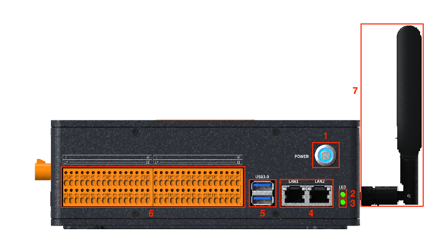
7.3.1 Controller Front Panel
The structure of the controller front panel is shown in the figure below:
| No. | Name | Function |
|---|---|---|
| 1 | Power button | Power On: When the device is powered off, press and hold the power key for 2 seconds then release it. Power Off: When the device is running normally, press and hold the power key for 2 seconds then release it. Forced Shutdown: Under any working state of the device, press and hold the power key for 10 seconds, and the device will cut off power and shut down immediately. Power Indicator Light: Remains off when power is disconnected, and stays lit when power is connected. |
| 2 | Connection Indicator Light | Off or constantly off during startup; after power-on, slow flashing at 0.5Hz while waiting for the teach pendant to start; steady light when the teach pendant is connected. |
| 3 | Power indicator light | Slow flashing at 0.5Hz when powered on, and steady off when powered off. |
| 4 | Ethernet port | Gigabit Ethernet port for remote access and control. |
| 5 | USB 3.0 port | For device connection, software upgrade and project file export. |
| 6 | I/O Interface | Realize signal connection of external devices and system expansion. |
| 7 | WiFi antenna | Wirelessly connected wireless handheld tablet |
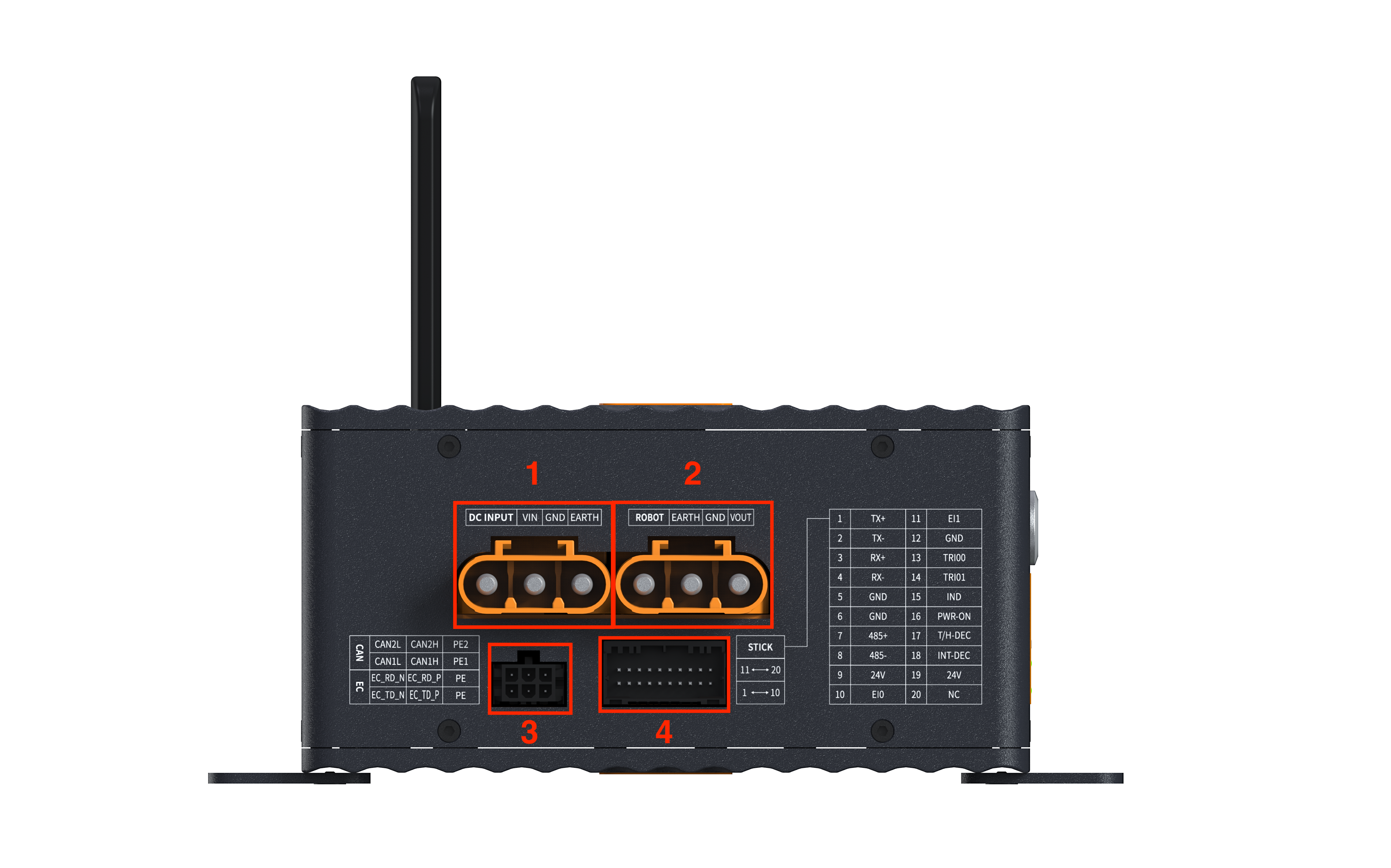
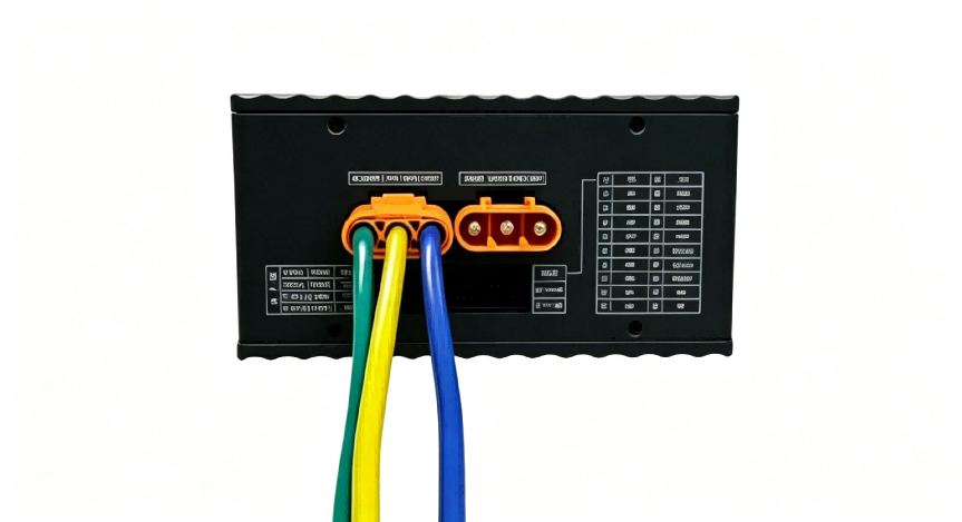
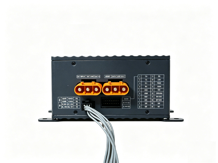
7.3.2 Controller Rear Panel
The structure of the rear panel of the controller is shown in the figure below:
| No. | Name | Function |
|---|---|---|
| 1 | DC power input | DC 96V DC power input for powering the control box. |
| 2 | Robot Power Output (ROBOT Interface) | Robot power input, used to supply power to the robot body. |
| 3 | CAN/EtherCAT | Robot communication input, used for communication between the control box and the robot body. |
| 4 | Controller interface | Connect the control handle to the interface of the control box. |
7.4 Wiring Instructions
7.4.1 Robot Cable Wiring
First, insert the aviation plug of the robot body cable into the ROBOT port of the controller, then fasten the buckles on both sides. The detailed operation is shown in Figure 7-4.
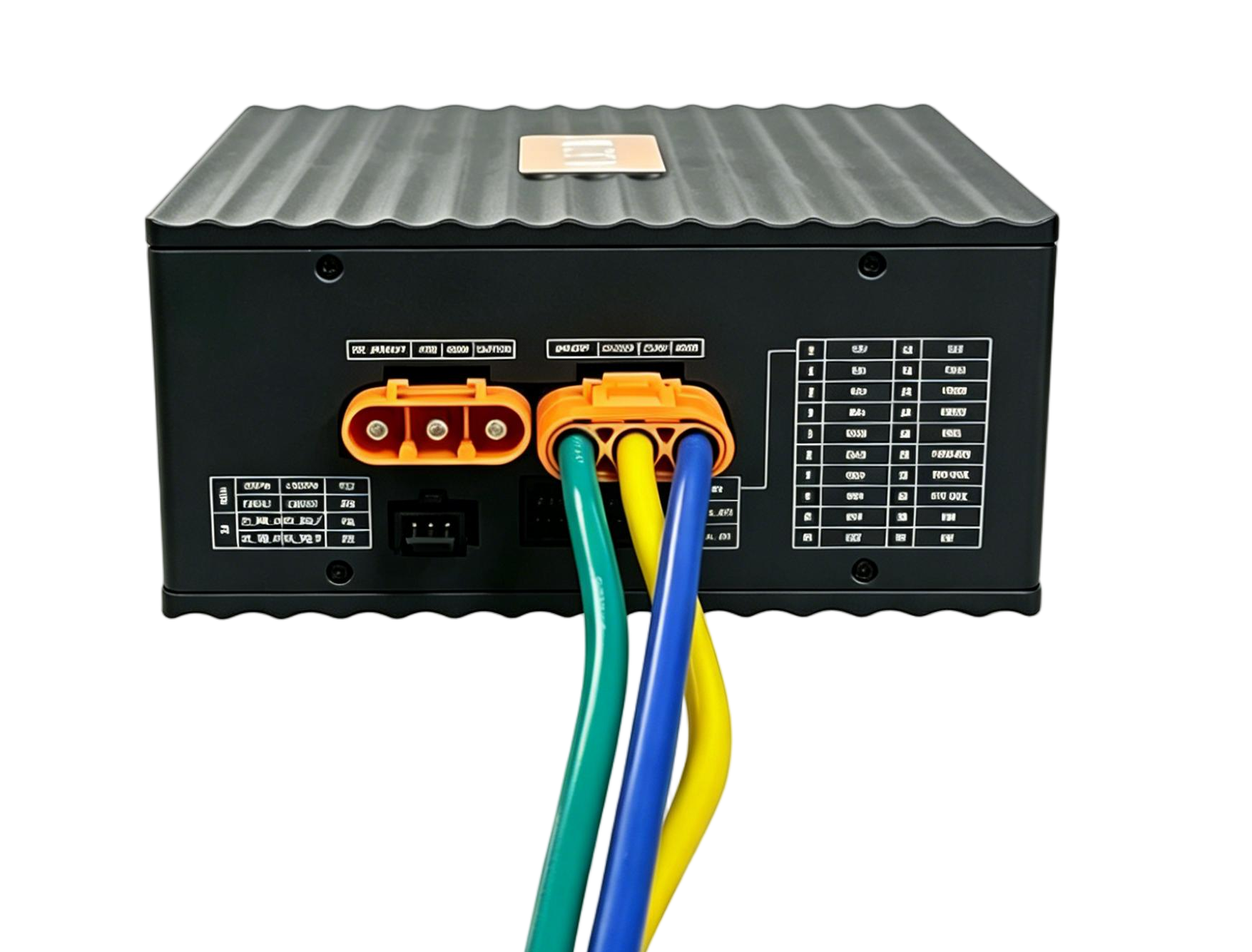
7.4.2 Power Wiring
The rated input voltage of the control box is DC 96V. The DC power cable must be connected to the DC power input port of the control box when the power is cut off, and the wiring is shown in Figure 7-5.
7.4.3 Wiring of Robot Communication Input Interface
The robot communication input interface is used for communication between the controller and the robot body. The wiring is shown in Figure 7-6.
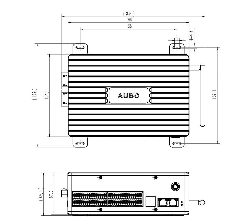
7.5 Installation Instructions
The control box supports two installation methods: front mounting and vertical mounting. During installation, a gap of at least 50 mm must be reserved on the installation side to provide sufficient heat dissipation space for the control box.
After mounting the front-mount brackets to the bottom of both sides of the control box, place the control box on a flat and stable mounting surface and fasten it to the surface with 4 M3*8mm screws as shown in Figure 7-7. Its mechanical dimensions are illustrated in Figure 7-8.
7.6 Power-On
Place the controller in an appropriate position.
Complete cable connections for the controller following the instructions in the preceding chapters.
Verify that all controller cables are securely connected, including the power cable, robot arm communication interface, control handle, etc.
Connect the power cable and turn on the power switch; the power indicator on the front panel of the controller will flash slowly.
After the teach pendant starts up and connects successfully, the connection indicator lights up. You can then power on and operate the robot arm normally.
7.7 Power-Off
Normal Power-Off Methods
Method 1: Press and hold the controller power button for 2 seconds, toggle off the power switch, then disconnect the power cord.
Method 2: Click the [Shutdown] button on the teach software interface, toggle off the power switch, then disconnect the power cord.
Method 3: Press and hold the power button on the control handle, toggle off the power switch, then disconnect the power cord.
Forced Power-Off
Method 1: Press and hold the controller power button for 10 seconds.
Method 2: Press and hold the power button on the control handle for 10 seconds.
Method 3: Unplug the power cord directly or turn off the power switch immediately.
| Sign | Description |
|---|---|
| 1. Do not shut down the system by unplugging the power cord directly from the socket; this may corrupt the robot's file system and cause malfunctions. |
8 Electrical Interfaces
8.1 Overview
The CB-G40-MINI controller is equipped with a variety of electrical interfaces to meet the requirements of diverse automated application scenarios. It integrates functions including robot motion control, safety logic processing and communication with external devices. See Table 8-1 for a summary of terminal interfaces.
| Interface Type | Category | Interface Name |
|---|---|---|
| User I/O | Safety Output | COM-CO / CO00~CO03 (MCU side), CO10~CO13 (3576 side) |
| Safety Input | COM-CI / CI00~CI03 (MCU side), CI10~CI13 (3576 side) | |
| RS485 Communication | 485- (RS485-B) / 485+ (RS485-A) / GND (RS485-GND) | |
| DC24V Output | V24+ (24V output positive) / V24- (GND) | |
| Remote Control | RM+ / RM- (user remote power on/off control) | |
| Power Detection | NC (power failure detection, ≤DC24V) | |
| Digital Input (DI) | COM-DI / DI00~DI07 (MCU-side general input) | |
| Digital Output (DO) | COM-DO / DO00~DO07 (MCU-side general output) | |
| Analog Output (AO) | AO1 / AO2 (digital-to-analog conversion signal 0/1, 0~5V) / AG (AGND) | |
| Analog Input (AI) | AI1 / AI2 (analog-to-digital conversion signal 0/1, 0~5V) / AG (AGND) | |
| Power Interface | Main Power | DC96V (96V version) / DC48V (48V version) / GND / PE (protective earth) |
| Communication Interface | CAN (multiplexed with EtherCAT) | GND_CAN1 / CAN1_H (CAN1/+) / CAN1_L (CAN1/-) / GND_CAN7 / CAN7_H (CAN7/+) / CAN7_L (CAN7/-); multiplexed with ENET_TD_P (EtherCAT/TX+) / ENET_TD_N (EtherCAT/TX-) / ENET_RD_P (EtherCAT/RX+) / ENET_RD_N (EtherCAT/RX-) |
| Handle Interface | Ethernet Communication | TX+ / TX- / RX+ / RX- |
| RS485 Communication | 485+ (RS485+) / 485- (RS485-) | |
| Emergency Stop | EI0 (emergency stop/NC) / EI1 (emergency stop NC1) | |
| Three-Position Switch | TRI00 (three-position switch/NO1) / TRI01 (three-position switch/NO) | |
| Power | 24V (24V+ power supply) / GND | |
| Control / Detection | PWR-ON (power on/off/NO) / IND (power-on indicator/+) / T/H-DEC (handle detection signal) / INT-DEC (aviation plug insertion signal) | |
| Reserved | NC |
8.2 Electrical Warnings and Precautions
When designing, installing, and deploying applications of the robot and G40-Mini controller, you must strictly abide by the following warnings and precautions. These warnings and precautions shall also be observed during all maintenance work.
| Sign | Description |
|---|---|
| 1. Please ensure that all equipment that shall not be exposed to water is kept dry. If water enters the product, cut off the power supply and contact your supplier. 2. Only use the original cable of the robot. Do not use the robot in applications where the cable needs to be bent. If longer cable or flexible cable is required, contact your supplier. 3. All GND connectors mentioned in this document are only applicable to power supply and signal transmission. For protective earthing (PE), use the screw connector marked with the earthing mark in the controller. The grounded connector shall have a current rating of at least the highest current in the system. 4. Be careful when installing the robot I/O interface cable. |
| 1. Never connect safety signals to a non-safety PLC with an inappropriate safety level. Failure to observe this warning may result in serious injury or even death due to the failure of a safety stop function. 2. During the wiring of the controller electrical interfaces, the controller must be powered off. |
| 1. Interference signals above the level specified in the IEC standard will cause abnormal behavior of the robot. High or excessive exposure to this signal level will cause permanent damage to the robot. EMC problems usually occur during welding and are usually indicated by error messages in the log. AUBO (Beijing) Intelligent Technology Co., Ltd. shall not be liable for any loss caused by EMC problems. 2. The length of I/O cable used to connect the controller to other machinery and equipment shall not exceed 30 m, unless extended testing demonstrates feasibility. |
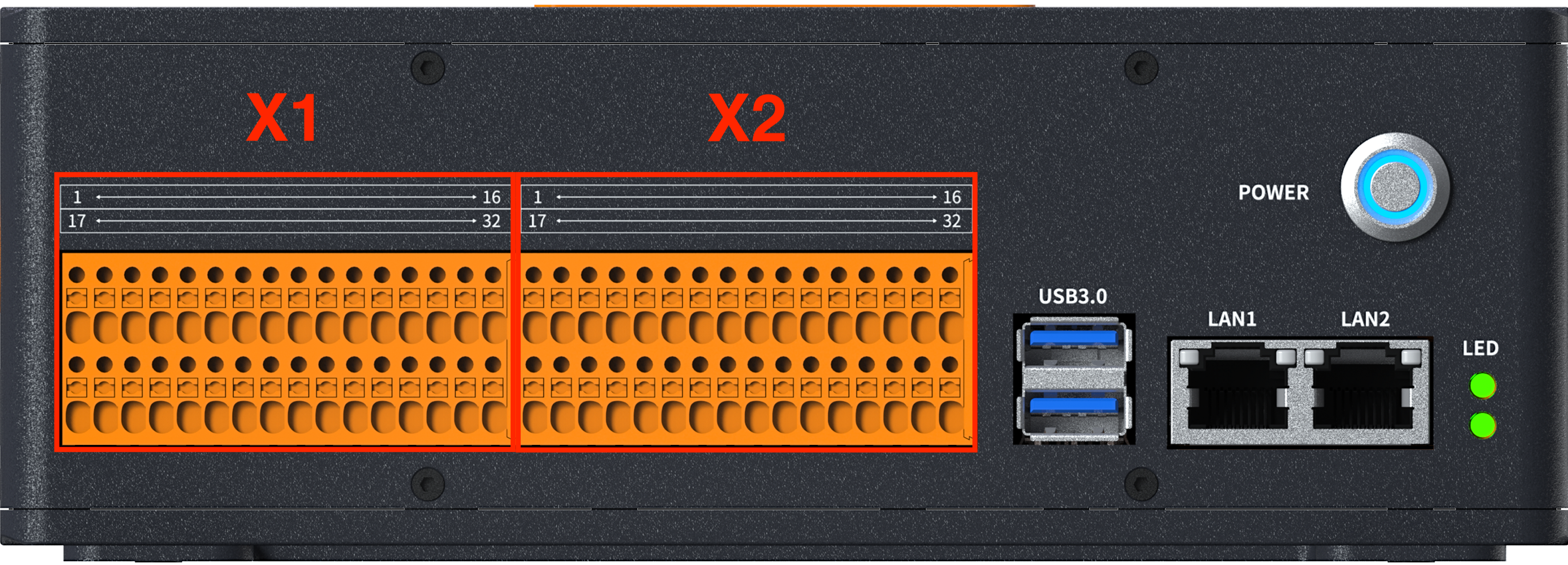
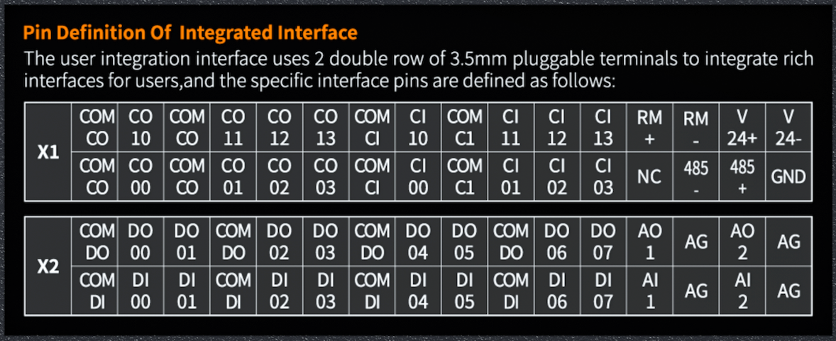
8.3 User I/O Interface
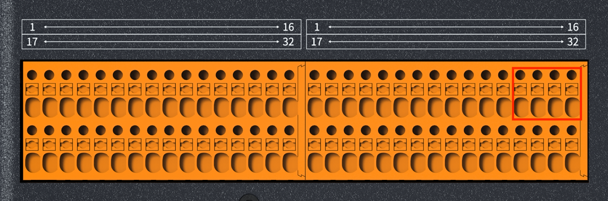
The CB-G40-MINI controller is equipped with two user I/O ports on the left and right sides, each adopting a 32-pin high-density connector as shown in Figure 8-1. The X1 port on the left side of the controller mainly supports safety I/O, RS485 communication, DC24V power output and remote control functions; the X2 port on the right side of the controller mainly provides general digital I/O and analog I/O functions. These two ports are hereinafter referred to as the "Left I/O Port" and "Right I/O Port".
8.3.1 RS485 Interface
Pins 30, 31 and 32 of the left I/O interface correspond to RS485-, RS485+ and GND respectively, as shown in Figure 8-2. They can be used for Modbus RTU communication.
| Pin Number | Name | Function |
|---|---|---|
| 30 | 485- | RS485-B |
| 31 | 485+ | RS485-A |
| 32 | GND | RS485-GND |
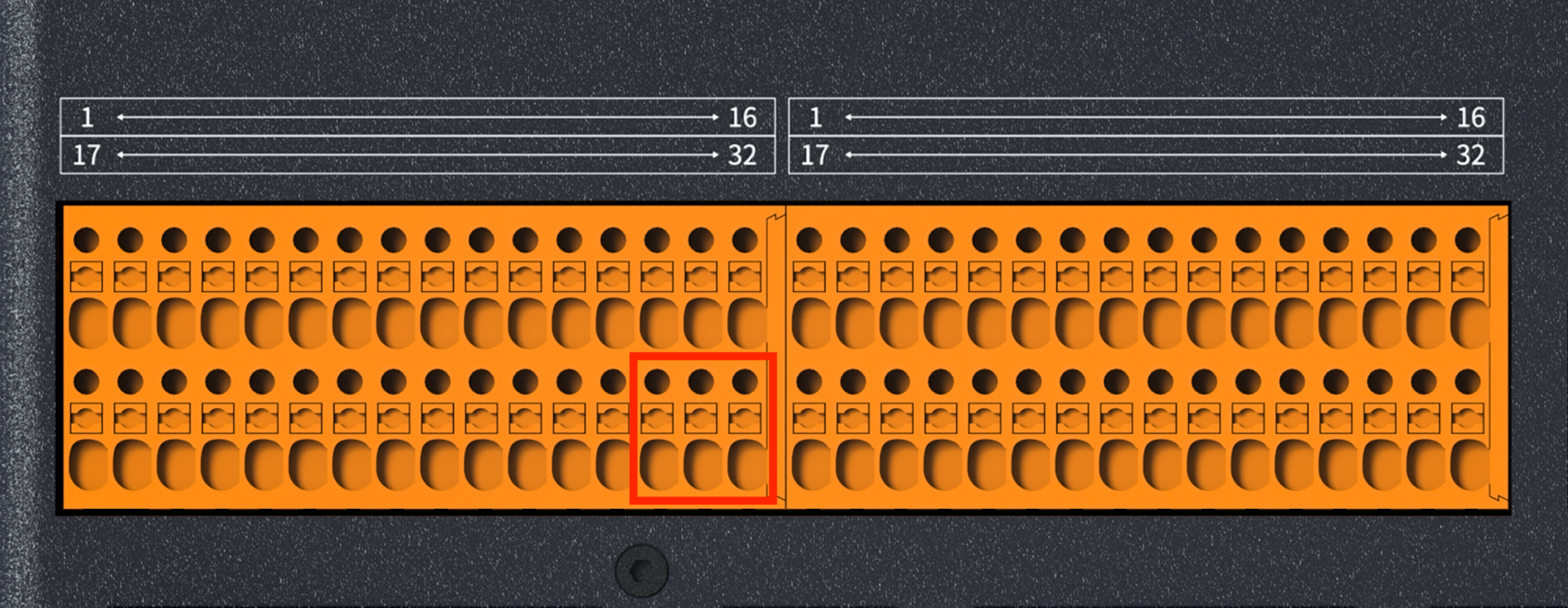
8.3.2 DC24V Output Power Supply
Pins 15 and 16 of the left I/O interface correspond to the V24+ and V24- output terminals respectively, as shown in Figure 8-3.
| Pin Number | Name | Function |
|---|---|---|
| 15 | V24+ | 24V |
| 16 | V24- | GND |
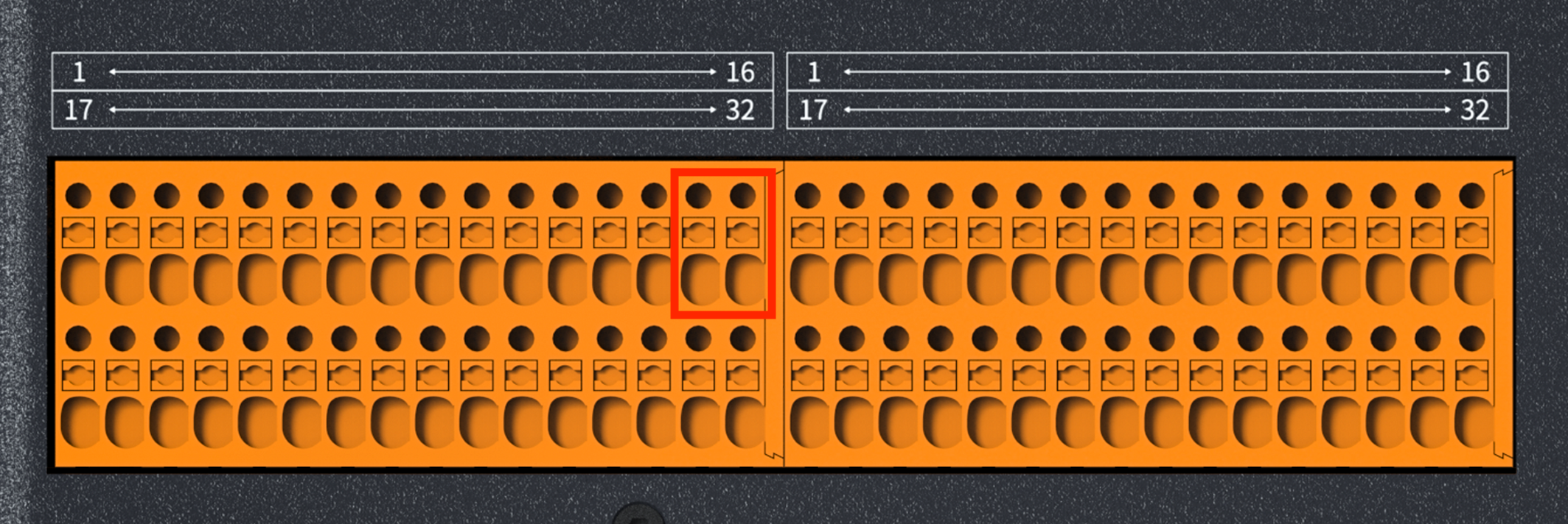
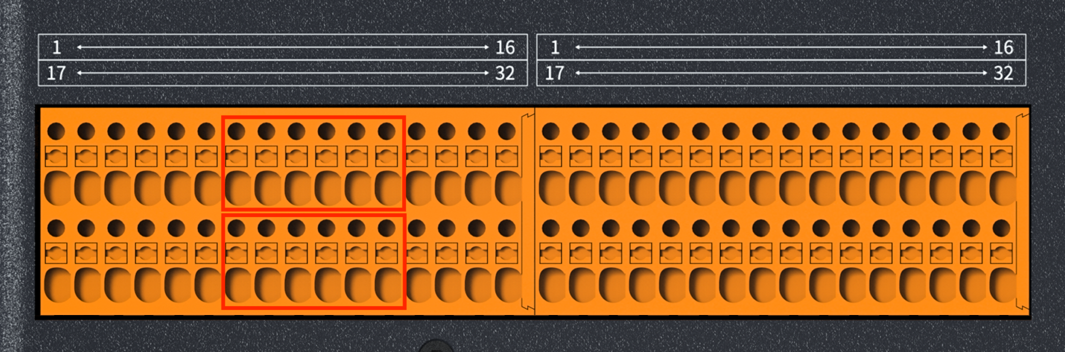
8.3.3 Safety Output
Pins 1-6 and 17-22 of the left-side I/O interface are safety outputs, as shown in Figure 8-4.
| Pin Number | Name | Pin Number | Name |
|---|---|---|---|
| 1 | COM-CO | 17 | COM-CO |
| 2 | CO10 | 18 | CO00 |
| 3 | COM-CO | 19 | COM-CO |
| 4 | CO11 | 20 | CO01 |
| 5 | CO12 | 21 | CO02 |
| 6 | CO13 | 22 | CO03 |
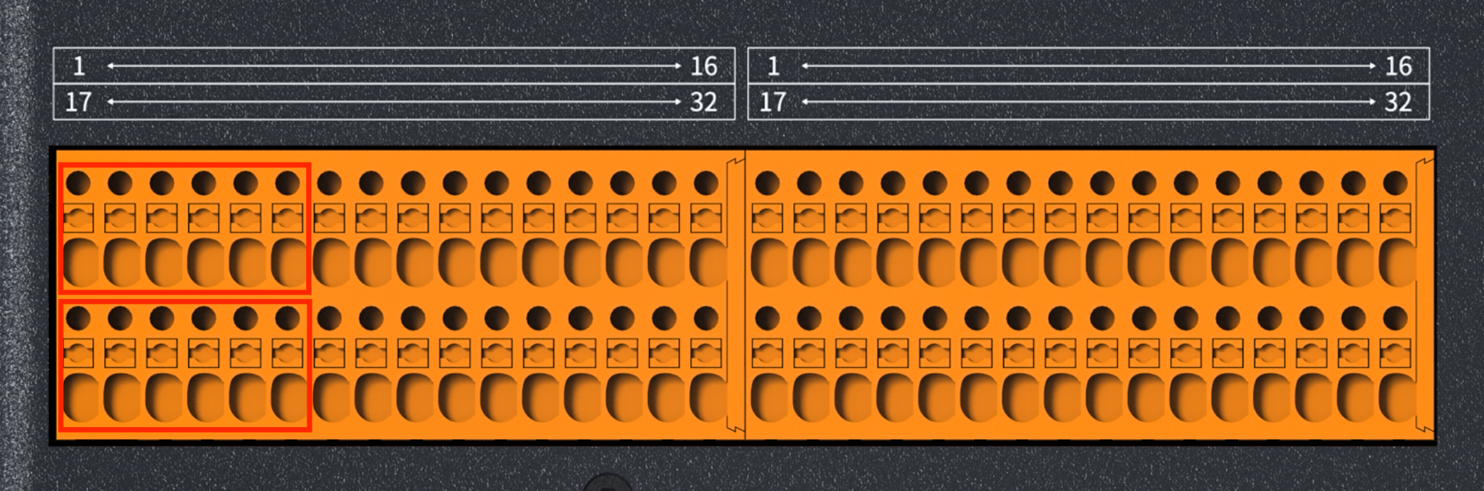
8.3.4 Safety Input
Pins 7-12 and 23-28 of the left I/O interface are safety inputs, as shown in Figure 8-5.
| Pin Number | Name | Pin Number | Name |
|---|---|---|---|
| 7 | COM-CI | 23 | COM-CI |
| 8 | CI10 | 24 | CI00 |
| 9 | COM-CI | 25 | COM-CI |
| 10 | CI11 | 26 | CI01 |
| 11 | CI12 | 27 | CI02 |
| 12 | CI13 | 28 | CI03 |
8.3.5 Remote control power on/off
Pins 13 and 14 of the left-side I/O interface serve as the remote power on/off control interface, as shown in Figure 8-6. The remote power switch interface can be used to turn the controller on or off.
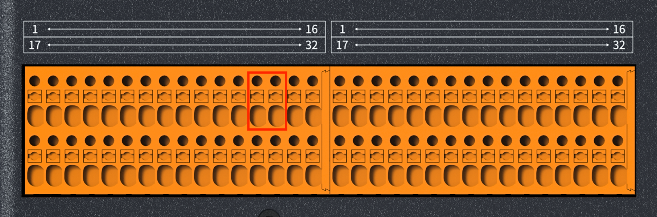
| Pin Number | Name | Function |
|---|---|---|
| 13 | RM+ | Users remotely control power supply on/off |
| 14 | RM- | Users remotely control power supply on/off |
8.3.6 Power-on detection of power supply
Pin 29 of the left I/O port is the power-on detection interface, and the voltage applied to this interface shall not exceed DC 24V, as shown in Figure 8-7.
| Pin Number | Name | Function |
|---|---|---|
| 29 | NC | Power-on detection of power supply |
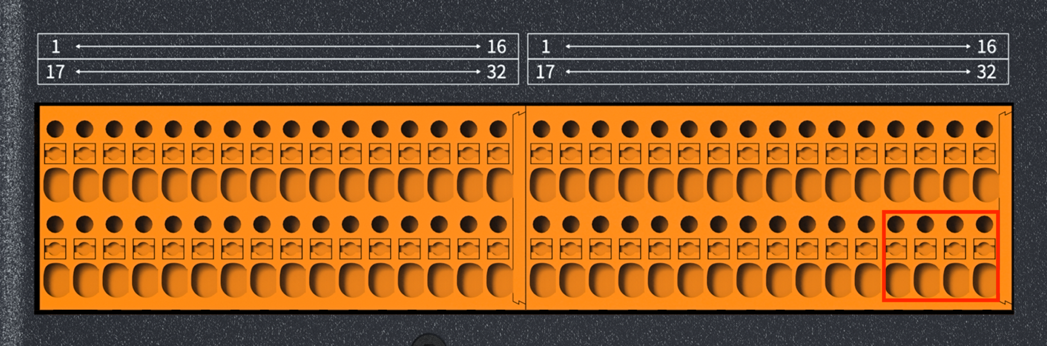
8.3.7 General Digital I/O Input Interface
Pins 17 to 28 of the right-side I/O interface are general-purpose digital I/O input ports, as shown in Figure 8-8.
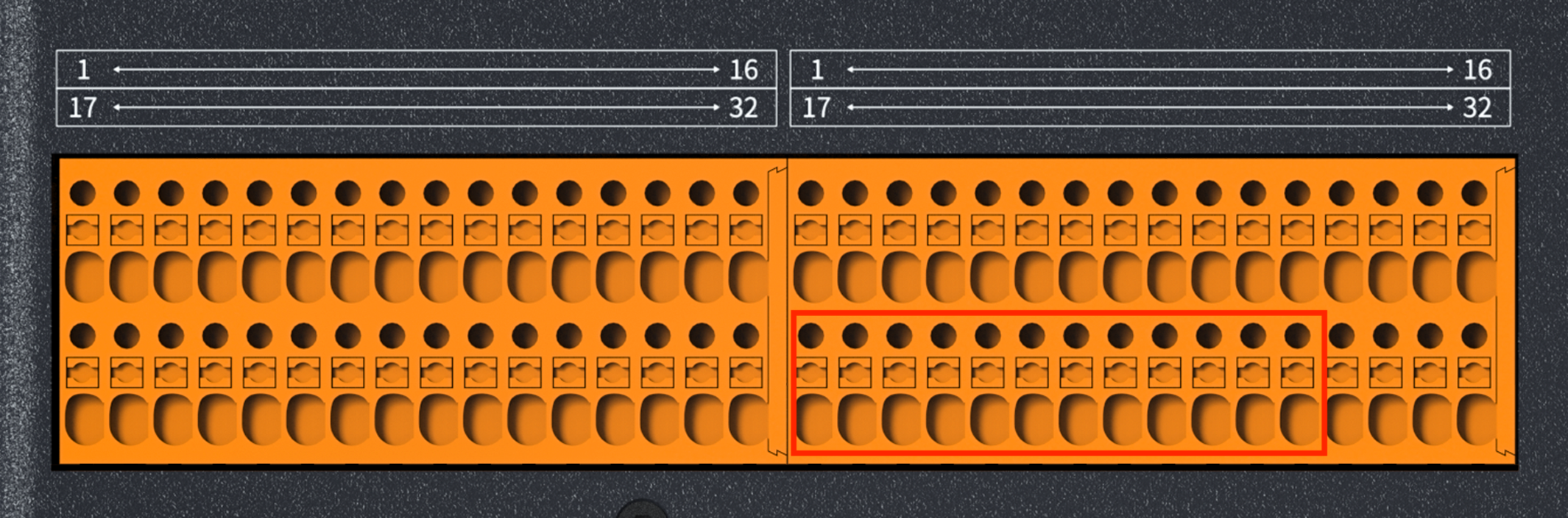
| Pin Number | Name |
|---|---|
| 17 | COM-DI |
| 18 | DI00 |
| 19 | DI01 |
| 20 | COM-DI |
| 21 | DI02 |
| 22 | DI03 |
| 23 | COM-DI |
| 24 | DI04 |
| 25 | DI05 |
| 26 | COM-DI |
| 27 | DI06 |
| 28 | DI07 |
8.3.8 General Digital I/O Output Interface
Pins 1 to 12 of the right-side I/O interface serve as general-purpose digital I/O output ports, as shown in Figure 8-9.
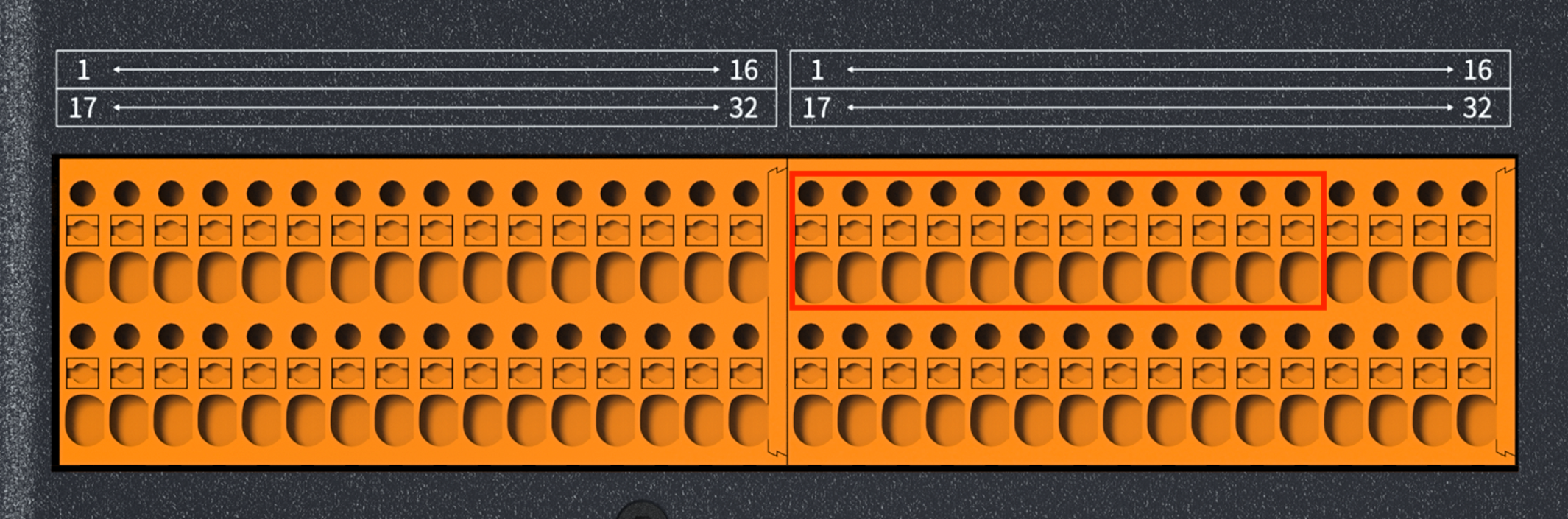
| Pin Number | Name |
|---|---|
| 1 | COM-DO |
| 2 | DO00 |
| 3 | DO01 |
| 4 | COM-DO |
| 5 | DO02 |
| 6 | DO03 |
| 7 | COM-DO |
| 8 | DO04 |
| 9 | DO05 |
| 10 | COM-DO |
| 11 | DO06 |
| 12 | DO07 |
8.3.9 Analog Output Interface
Pins 13 to 16 of the right-side I/O interface are analog output ports, which support a maximum analog output of 0-5V, as shown in Figure 8-10.
| Pin Number | Name | Function |
|---|---|---|
| 13 | AO1 | Digital-to-Analog Conversion Signal 0 |
| 14 | AG | AGND |
| 15 | AO2 | Digital-to-Analog Conversion Signal 1 |
| 16 | AG | AGND |
8.3.10 Analog Input Interface
Pins 29 to 32 of the right-side I/O interface are analog input ports, which support a maximum analog input voltage range of 0 to 5V, as shown in Figure 8-11.
| Pin Number | Name | Function |
|---|---|---|
| 29 | AI1 | Analog-to-Digital Conversion Signal 0 |
| 30 | AG | AGND |
| 31 | AI2 | Analog-to-Digital Conversion Signal 1 |
| 32 | AG | AGND |
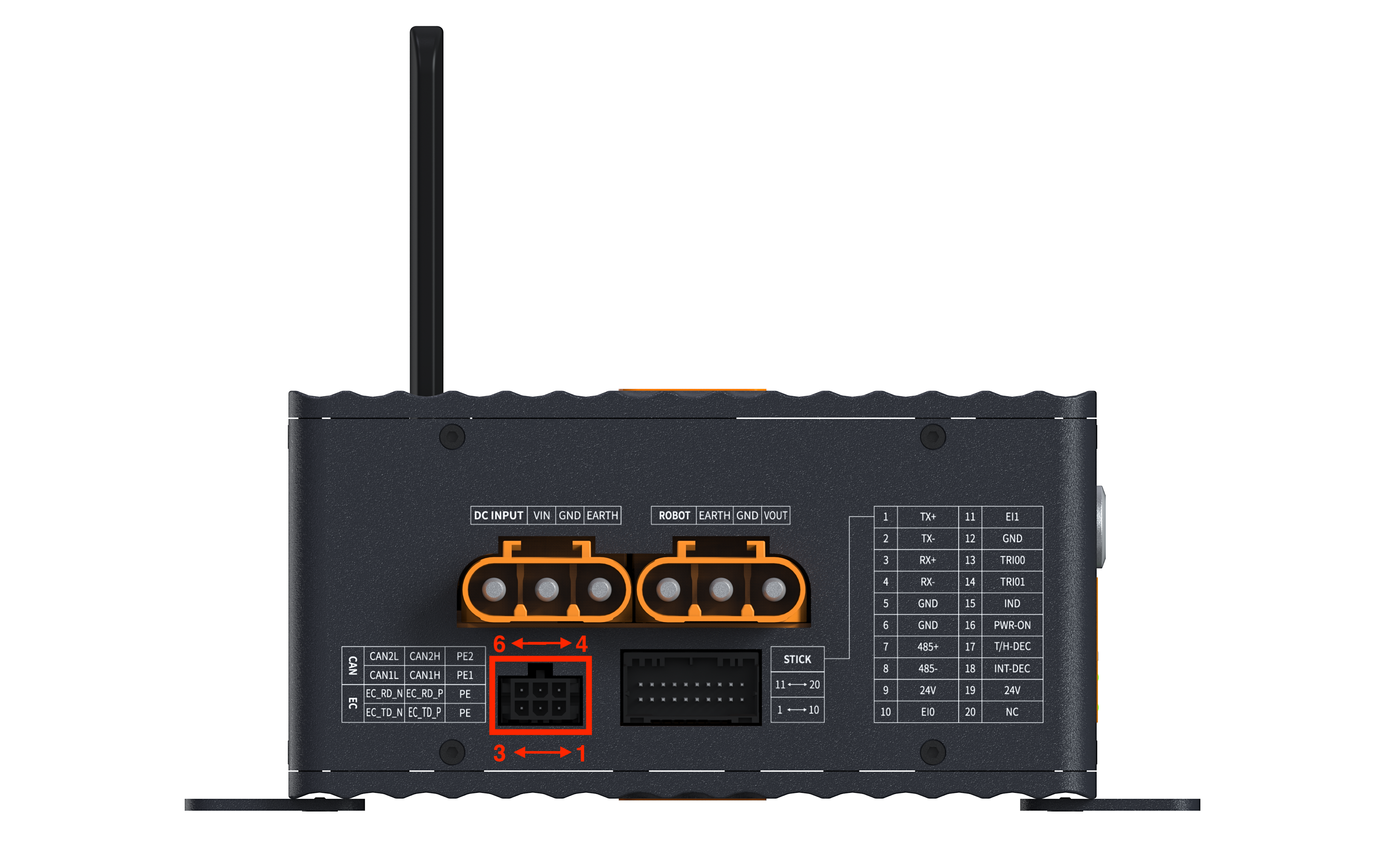
8.4 Power Interface
The controller power supply voltage is available in two versions: 96V and 48V. The power interface is shown in Figure 8-12.

| Plug position | Voltage Version | Pin Order from Left to Right |
|---|---|---|
| Plug on the left | 96V | DC96V → GND → PE |
| 48V | DC48V → GND → PE | |
| Plug on the right | 96V | PE → GND → DC96V |
| 48V | PE → GND → DC48V |
8.5 Communication Interface of Robotic Arm
The pin layout of the communication interface for the robotic arm is shown in Figure 8-13.
| CAN Interface Definition (Multiplexed with EtherCAT) | ||||
|---|---|---|---|---|
| Pin | Function 1 | Function 2 | ||
| 1 | GND_CAN1 | CAN1-GND | ||
| 2 | CAN1_H | CAN1/+ | ENET_TD_P | EtherCAT/TX+ |
| 3 | CAN1_L | CAN1/- | ENET_TD_N | EtherCAT/TX- |
| 4 | GND_CAN7 | CAN7-GND | ||
| 5 | CAN7_H | CAN7/+ | ENET_RD_P | EtherCAT/RX+ |
| 6 | CAN7_L | CAN7/- | ENET_RD_N | EtherCAT/RX- |
8.6 Controller Interface
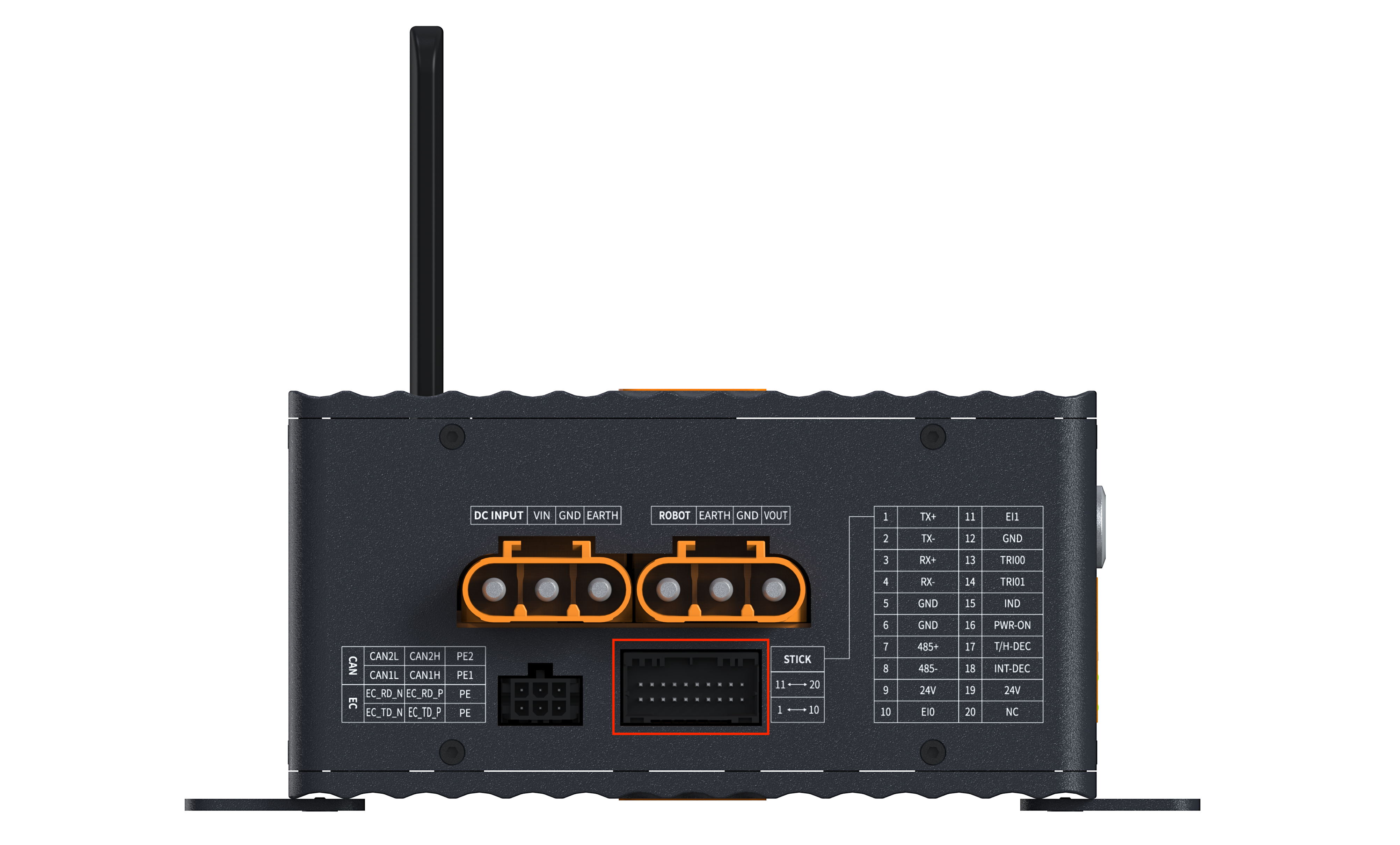
| Pin Number | Name | Function | Pin Number | Name | Function |
|---|---|---|---|---|---|
| 1 | TX+ | Ethernet/TX+ | 11 | EI1 | Emergency Stop NC1 |
| 2 | TX- | Ethernet/TX- | 12 | GND | GND |
| 3 | RX+ | Ethernet/RX+ | 13 | TRI00 | Tri-state Switch / NO1 |
| 4 | RX- | Ethernet/RX- | 14 | TRI01 | Tri-state switch / NO |
| 5 | GND | GND | 15 | IND | Power indicator light / + |
| 6 | GND | GND | 16 | PWR-ON | Power On/Off / NO |
| 7 | 485+ | RS485+ | 17 | T/H-DEC | Controller detection signal |
| 8 | 485- | RS485- | 18 | INT-DEC | Aviation plug insertion signal |
| 9 | 24V | 24V Power Positive | 19 | 24V | 24V power supply positive terminal |
| 10 | EI0 | Emergency Stop / Normally Closed | 20 | NC |
9 Usage of the Control Handheld
9.1 Introduction
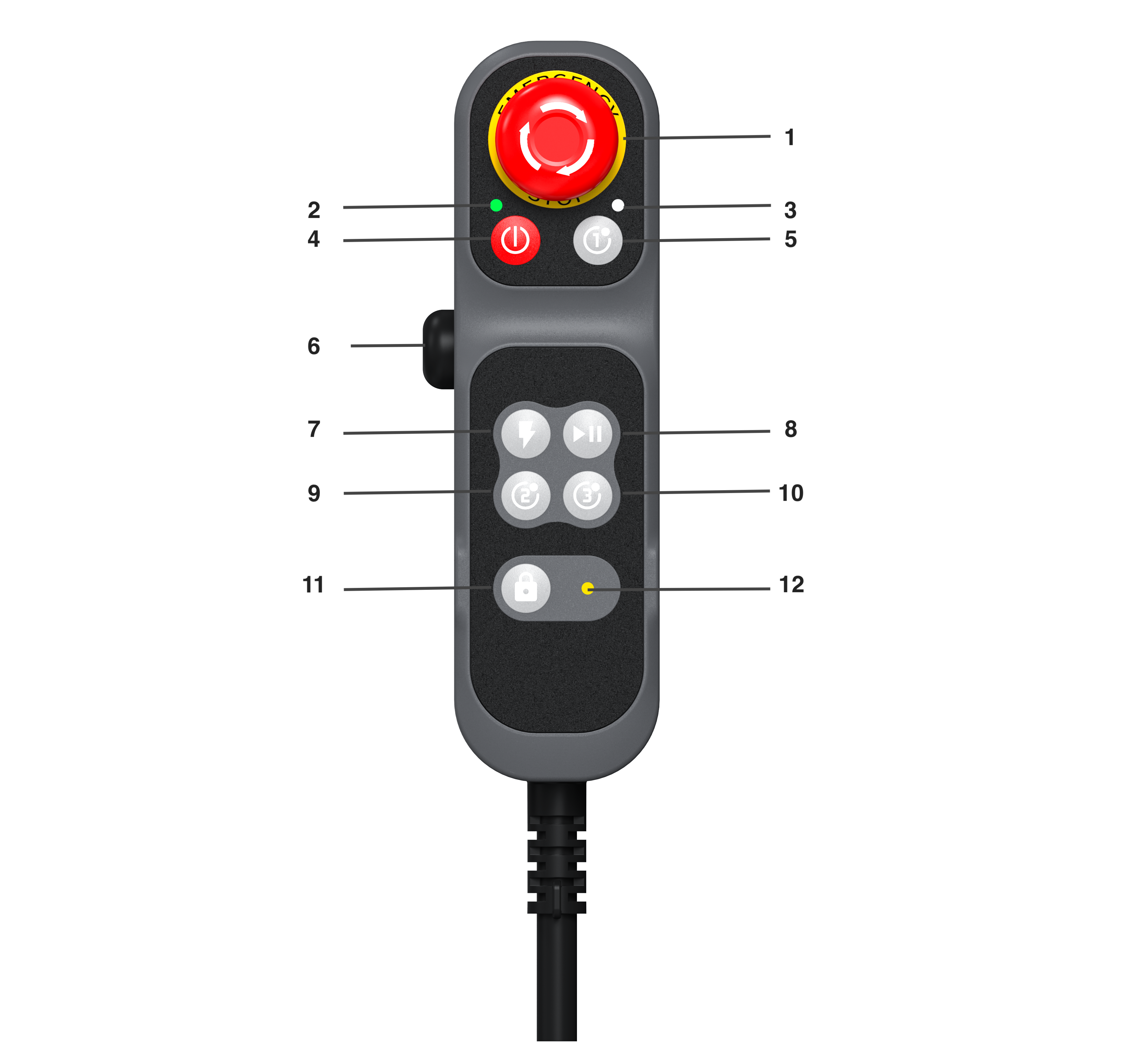
The control handheld enables quick operations for the robot system. You may enable or disable the control handheld function via the AUBO STUDIO teach pendant software; this function is enabled by default upon factory delivery. Magnets are fitted on the rear side of the control handheld for magnetic mounting. Its structure is shown in Figure 9-1.
| No. | Name | Function |
|---|---|---|
| 1 | Emergency Stop Button | Press down to activate emergency stop for the robot. Rotate the button following the marked direction to restore normal status. |
| 2 | Power Indicator Light | Shows the power-on/power-off state of the controller: Steady off: Controller powered off Slow flash (1 Hz): Controller booting up Fast flash (4 Hz): Waiting for teach pendant startup Steady on: Teach pendant started, available for APP scan & connection; robot arm unpowered standby Breathing flash: Robot arm powered on standby Fast flash (4 Hz, lasts 3s): Searching for robot (teach pendant control mode) Slow flash (1 Hz): Shutting down |
| 3 | Key Indicator Light | Displays trigger status of buttons: 1. Flashes once each time a handheld button is tapped. 2. Steady on when long-pressed; turns off once released. |
| 4 | Power On/Off Button | 1. Power On: Press and hold for 2s then release. A "beep" tone sounds to start controller bootup. After approx. 20s, a second "beep" plays, the handheld power indicator flashes, and bootup completes. 2. Power Off: Press and hold for 2s then release. Power indicator goes out, and a double "beep-beep" tone confirms shutdown. 3. Forced Shutdown: Press and hold for 10s under any operating state for forced shutdown; power indicator turns off with double "beep-beep" confirmation tone. |
| 5, 9, 10 | Custom Buttons | Users may customize and configure the functions of these buttons in the AUBO STUDIO teach software. |
| 6 | 3-Position Enable Switch | This 3-position enable switch has three travel stages: 1. Released – OFF (initial state) 2. Half-pressed – ON 3. Fully pressed – OFF 4. Default Mode: It acts as a drag teach button by default. Drag teaching is available under the ON state; OFF state triggers safe stop (power remains on). 5. Manual Mode: Switchable to Manual Mode via the software interface. In Manual Mode, the robot arm supports normal manual control under the ON state; OFF state activates robot safe stop. |
| 7 | Robot Power On/Off Button | Controls power supply and enable status of the robot arm: 1. Robot Arm Power On: When the arm is powered off, short-press the button; the buzzer emits one "beep" and the arm starts powering up. After around 20 seconds, a second "beep" sounds, the power indicator changes from flashing to steady on, and power-up completes. 2. Robot Arm Enable (Brake Release Operation): When the arm is powered on but not enabled, short-press the button. The arm vibrates, and each of the six joints clicks sequentially to release the braking system; normal operation of the arm is available afterward. 3. Robot Arm Power Off: When the arm is powered and enabled, press and hold the button for 2 seconds then release. The arm deactivates and powers down; the power indicator switches from steady on to flashing, and a double "beep-beep" tone confirms power-off completion. |
| 8 | Program Start/Stop Button | This button controls the start, stop, pause and resume of robot arm programs. It enables quick operation without the teach pendant, meeting demands for on-site operation, unit deployment, maintenance and debugging. 1. Program Start: Press and hold the start/stop button on the control handheld for 2 seconds then release to start the program. A single "beep" from the buzzer indicates program execution. If no default program is set, the robot arm will not move and the buzzer gives no alert tone. 2. Program Pause/Resume: While the program is running, short-press the button to pause or resume the program; a single "beep" signals pause/resume status. 3. Program Termination: Press and hold for 2 seconds then release to fully stop the program (it cannot be resumed afterward and must be restarted manually). A double "beep-beep" tone confirms program abort. |
| 11 | Lock/Unlock | Handheld lock button: Enables locking and unlocking of the handheld to prevent accidental key presses during program operation. 1. Lock: When the handheld is unlocked, press and hold the button for 2 seconds then release. A single beep sounds, the lock indicator light stays steadily on, and all buttons except the emergency stop are disabled. 2. Unlock: When the handheld is locked, press and hold the button for 2 seconds then release. A double beep sounds, the lock indicator light turns off, and all handheld buttons return to normal operation. |
| 12 | Handheld Lock Indicator Light | Shows the lock status of the handheld: 1. Steady On: Handheld locked; operations of other buttons are invalid. 2. Steady Off: Handheld unlocked; all other buttons function normally. |
9.2 Other Instructions for the Handle
Combined indicator lamp: Emergency stop fault alert for the handheld
If the Power Indicator Light and Key Indicator Light flash rapidly simultaneously, it indicates an abnormal connection of the handheld emergency stop circuit. This light alarm has the highest priority; once triggered, it forcibly overrides the original status of all indicator lights, and this flashing state remains unchanged until the fault is cleared.
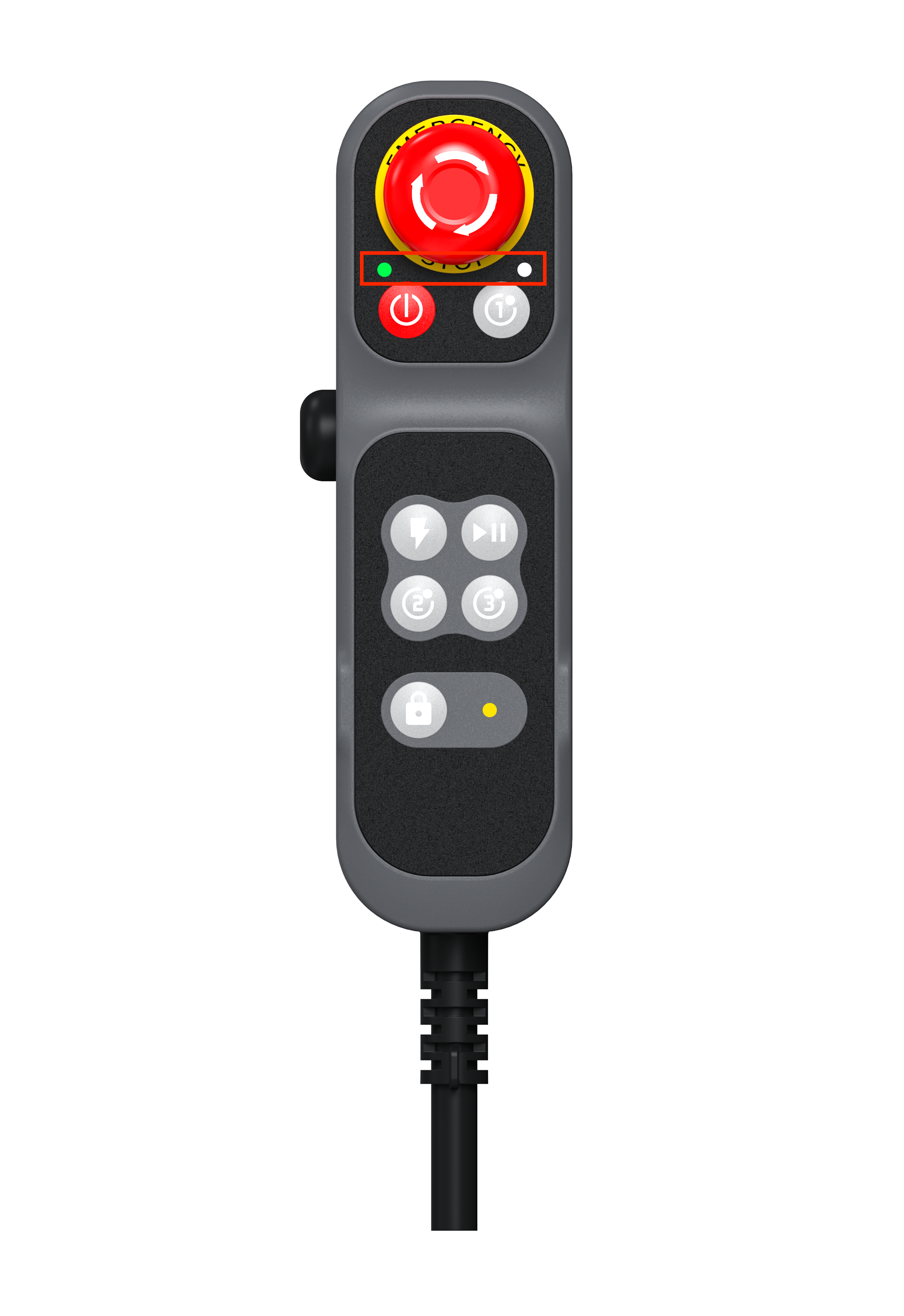 Figure 9-2 Handheld Emergency Stop Fault Indicator Light
Custom Functions
Users may configure functions for custom buttons within the teach software. Available configurable functions are listed in the table below. Refer to the AUBO STUDIO Software Manual for detailed operation steps.
Table 9-2 Custom Button Function ListButton Function Definition Custom Button Return to Home Position, triggered by long press Drag Teach, triggered by long press Record Feature Point, triggered by short press Trajectory Playback, triggered by short press
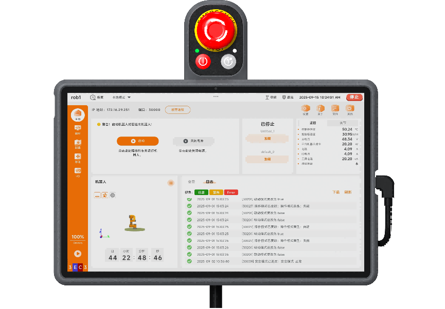
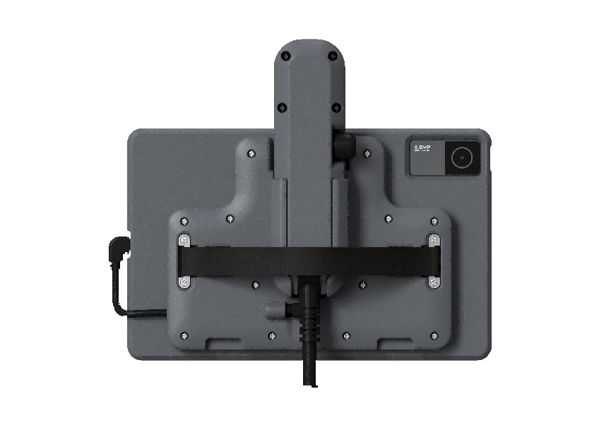
9.3 G-STICK Handheld Kit
The G-series handheld is supplied with a tablet back clip kit as shown in the figure. This accessory enables assembly connection between the handheld and tablet to optimize operation experience.
10 Appendix A Glossary
Technical Specifications
| Controller Model | CB-G40-Mini | |
| Controller Dimensions (LWH) | 234mm x 169mm x 69.9mm | |
| Controller Weight | Approx. 8kg | |
| IP Rating | IP20 (IP43 customizable) | |
| Power Supply | 96VDC | |
| I/O Ports | Digital Input | 8 (configurable) |
| Digital Output | 8 (configurable) | |
| RS485 | 1 | |
| I/O Power | Output Voltage: 24V Output Current: Max 3A | |
| Operating Temperature | -10℃~55℃ | |
| Transport & Storage Temperature | -40℃~60℃ | |
| Humidity | 95% Relative Humidity (Non-condensing) | |
| Cooling Method | Air Cooling | |
| Cable Length | Robot Arm Cable | 5m |
| Teach Pendant Cable | 4m | |