
AUBO-CB-AGV-V2 Controller User Manual
1 About This Manual
1.1 Version Information
| Item | Content |
|---|---|
| Manual Name | AUBO-CB-AGV-V2 Controller User Manual |
| Manual Version | v1.0.2* |
| Release Date | 2026-09-22 |
| Applicable Product | AUBO-CB-AGV-V2 Controller |
This manual is regularly reviewed and revised. Updates will be released as new versions. The contents and information in this manual are subject to change without prior notice.
Before installing or using the product, read this manual thoroughly and keep it for future reference.
All images in this manual are for illustration only. Refer to the actual product delivered.
1.2 Copyright and Disclaimer
This manual is the proprietary property of AUBO (Beijing) Intelligent Technology Co., Ltd. Without the written permission of AUBO (Beijing) Intelligent Technology Co., Ltd., it may not be photocopied, reproduced in whole or in part, or converted into any other form.
AUBO (Beijing) Intelligent Technology Co., Ltd. shall not be liable for any errors or omissions that may appear in this manual, or for any incidental or indirect damages caused by the use of this manual and the products described herein.
Copyright © 2015-2026 AUBO. All rights reserved.
1.3 Purpose of This Manual
This manual provides instructions for installation, commissioning, pre-operation inspection, maintenance, repair, handling, storage, and disposal of the AUBO-CB-AGV-V2 controller.
This manual does not replace the system integrator's risk assessment, on-site safety design, operating instructions, or applicable laws, regulations, and safety standards of the country/region where the system is used.
1.4 Intended Use of the Controller
The AUBO-CB-AGV-V2 controller may be used for general industrial equipment and general commercial equipment only under the specified environmental conditions. For details about the operating environment and operating conditions, refer to the technical specifications table.
The AUBO-CB-AGV-V2 controller has special safety-level characteristics. The use of sharp end effectors or tool connectors may be hazardous.
Prohibited uses include, but are not limited to, the following:
- Use in hazardous environments such as flammable or explosive environments.
- Use in devices for moving or transporting people or other animals.
- Use in devices such as medical equipment involving human life.
- Use in devices that have significant social or public impact.
- Use in vibration environments such as vehicles or ships.
- Use as a climbing tool.
1.5 Intended Readers
This manual is intended for the following professionals:
- Installation personnel
- Commissioning and operating personnel
- Maintenance and repair personnel
- Safety management personnel
1.6 Operating Prerequisites
Personnel who read and use this manual shall meet the following requirements:
- Have received relevant training provided by AUBO or an AUBO-authorized distributor.
- Have basic knowledge required for installation and maintenance of mechanical, electrical, and automation equipment.
- Be familiar with on-site safety management requirements and have basic risk identification and safe operation awareness.
- Have read and understood the safety instructions in this manual and related documents.
1.7 Related Documents
When using this manual, it is recommended to also read the following document:
1.8 More Information
For more information about products, services, training, or technical support, visit https://www.aubo-robotics.cn.
2 Safety
2.1 Safety Instructions
This chapter introduces the basic safety principles that must be followed when operating the controller or robot system. Integrators, users, and operators must read this chapter carefully and strictly follow the instructions marked with safety warning signs.
Because robot systems are complex and potentially hazardous, this manual cannot cover every possible hazard scenario. Users and integrators shall perform risk assessments based on the actual application, end tools, peripheral equipment, working environment, and personnel activity range, and shall take appropriate risk reduction measures.
2.2 Safety Warning Signs
This manual uses the following safety warning signs to indicate important safety information. When you see these signs, read and follow the corresponding instructions carefully.
| Sign | Level | Description |
|---|---|---|
 | DANGER | Indicates a potentially hazardous situation which, if not avoided, can result in death or serious injury. |
 | WARNING | Indicates a potentially hazardous situation which, if not avoided, can result in personal injury or serious equipment damage. |
 | CAUTION | Indicates a potentially hazardous situation which, if not avoided, can result in minor personal injury or equipment damage. Items marked with this symbol may sometimes lead to serious consequences depending on the specific circumstances. |
 | NOTICE | Indicates a situation which, if not avoided, can result in personal injury or equipment damage. Items marked with this symbol may sometimes lead to serious consequences depending on the specific circumstances. |
2.3 General Safety Rules
When operating the controller and its related equipment, the following basic safety guidelines must always be observed. This section lists general safety requirements. Safety instructions for specific scenarios are described in the relevant chapters of this manual.
Install the robot and all electrical equipment according to the requirements and specifications in this manual.
Before using the robot and putting it into production for the first time, perform preliminary tests and inspections on the robot and its protective system.
Before starting the robot and system for the first time, check that the robot and system are complete, verify that operation is safe, and confirm that no damage is present. During this inspection, check compliance with applicable national or regional work safety regulations, and test all safety functions.
The user must check and ensure that all safety parameters and user programs are correct and that all safety functions work properly. Each safety function must be checked by personnel qualified to operate the robot. The robot may be started only after comprehensive and careful safety testing and after the required safety level has been reached.
The robot must be installed and commissioned by professional personnel according to installation standards.
After the robot is installed and constructed, a comprehensive risk assessment must be performed again and documented.
Safety parameters shall be set and changed only by authorized personnel. Passwords or isolation measures shall be used to prevent unauthorized personnel from changing or setting safety parameters. After safety parameters are changed, the related safety functions must be analyzed.
In case of an accident or abnormal robot operation, use the emergency stop switch to stop robot motion.
The robot arm has a collision detection function. During powered operation, if an external force exceeds the normal force range set by the user's safety parameters, the robot stops automatically to prevent machine damage or collision injury to operators.
This function requires the robot system to operate within its normal operating range and to use an AUBO series controller. If users develop their own controller, the robot will not have the above function. Users are responsible for any resulting hazards or consequences.
Connecting different machines together may increase hazards or introduce new hazards. Always perform a comprehensive risk assessment of the entire installation. When different safety and emergency stop performance levels are required, always select the highest performance level.
AUBO (Beijing) Intelligent Technology Co., Ltd. shall not be liable for machine damage or personal injury caused by improper operation of the machine.
Strictly Prohibited:
| Sign | Description |
|---|---|
| 1. It is strictly prohibited to start the robot system before safety inspection and risk assessment are completed. Before first startup, system integrity inspection, testing of all safety functions, verification of safety parameter correctness, and review of risk assessment documents must be completed. 2. It is strictly prohibited to power on the controller without connecting the protective earth wire (PE wire). Poor grounding may cause electric shock, equipment damage, or electromagnetic interference. 3. It is strictly prohibited to use the controller in humid environments or environments with conductive dust, which may result in injury or death. 4. It is strictly prohibited to manually switch the power supply system on and off frequently. Brake devices are installed inside the robot arm joint modules. They maintain robot posture when power is off. Do not manually switch the power supply system on and off frequently. It is recommended that the interval between each power-on and power-off be greater than 10s. 5. It is strictly prohibited to touch hot components while the equipment is running. Do not operate or touch the equipment while the robot is working or immediately after it stops working. Disconnect the power supply and wait one hour for the equipment to cool down. 6. It is strictly prohibited to modify safety parameters or bypass safety functions without authorization. |
Operating Rules:
| Sign | Description |
|---|---|
| 1. Ensure that the controller and related equipment are securely installed. Unstable installation may cause equipment to fall off or operate abnormally. 2. Ensure that the robot system has sufficient workspace without obstacles, sharp corners, or pinch points. The operator's head and face shall be outside the reachable range of the robot arm. 3. Do not connect safety equipment to general I/O interfaces. Use only dedicated safety interfaces. 4. Configure installation parameters correctly, including installation angle, TCP weight and offset, safety parameters, etc. 5. If the controller or robot system is damaged, do not continue using it. Stop the machine immediately and contact AUBO or an authorized service provider. 6. A safety assessment must be performed after each installation to confirm that all safety functions work properly. |
| 1. Check insulation and protective measures before transporting the controller. Handle it carefully during transportation to avoid impact. 2. Do not expose the controller to a strong magnetic field for a long time. Strong magnetic fields may damage the equipment. 3. Do not modify the controller without authorization. Any unauthorized modification will void the warranty, and AUBO shall not be liable for any resulting consequences. |
2.4 Personnel Safety
When operating the robot system, personnel safety shall take priority. Users and integrators shall take at least the following measures:
- Ensure that all related personnel have received training through AUBO official channels or AUBO-authorized distributors and fully understand safe, standardized operating procedures. For training inquiries: support@aubo-robotics.cn.
- During operation, tie up long hair, do not wear loose clothing, and do not wear jewelry. The robot may be ready to start even when stationary and shall be regarded as continuously running. Do not approach it unnecessarily.
- In an emergency where a person is trapped or confined, the joints may be forced to move by pushing or pulling the robot arm firmly. Manual movement of the robot arm without power drive is allowed only in emergencies and may damage the robot arm joints.
- Personnel shall not place the head, face, neck, fingers, or other body parts in areas where they may be hit, pinched, or entangled.
2.5 Responsibilities and Specifications
The controller is part of a complete robot system and does not constitute a complete machine by itself. Therefore, this manual does not cover the complete set of design, installation, and operating solutions for a complete robot, nor does it list all risk conditions that may affect the safety of peripheral equipment in the integrated system. The installation safety performance of complete robot equipment depends on the design and construction method of the complete integration solution. The equipment integrator shall perform risk assessment for the design and installation process of the complete integrated system according to applicable local laws, regulations, safety specifications, and industry standards.
All safety information contained in this manual shall not be regarded as a guarantee by AUBO (Beijing) Intelligent Technology Co., Ltd. Even if operators strictly follow all safety instructions in this manual, there is still a potential risk of personal injury or equipment damage.
AUBO (Beijing) Intelligent Technology Co., Ltd. continuously optimizes product performance and reliability and reserves the right to upgrade products without prior notice. We have made every effort to ensure that the contents of this manual are accurate and reliable, but we shall not be liable for omissions or errors in the document.
2.5.1 Integrator Responsibilities
The integrator assumes the following key responsibilities:
- Perform a comprehensive risk assessment of the complete robot system.
- Ensure that the design, installation, and commissioning of the entire system meet safety requirements.
- Provide necessary training for users and related operators.
- Develop complete system operating rules and emergency plans.
- Establish and maintain appropriate safety protection measures.
- Use appropriate methods during final installation to eliminate hazards or minimize all hazards to an acceptable level.
- Inform the end user of residual risks.
- Mark the integrator information on the robot.
- Archive all related technical documents and risk assessment reports.
2.5.2 Reference Standards
The integrator may refer to the following international standards when performing the risk assessment process:
| Standard No. | Name | Description |
|---|---|---|
| ISO 12100:2010 | Safety of machinery — General principles for design — Risk assessment and risk reduction | Basic framework for risk assessment |
| ISO 10218-2:2025 | Robots and robotic devices — Safety requirements — Part 2: Industrial robot systems and robot applications | Safety requirements for industrial robot integration |
| RIA TR R15.306-2014 | Technical report on industrial robots and robot systems — Safety requirements and task-based risk assessment method | Task-based risk assessment guide |
| ANSI B11.0-2010 | Safety of machinery — General requirements and risk assessment | U.S. machinery safety standard |
For applicable standards and regulatory guidance, visit the AUBO official website www.aubo-robotics.cn or consult local regulatory authorities.
2.6 Hazard Identification
Risk assessment shall consider potential hazards during normal use, commissioning, maintenance, cleaning, abnormal recovery, and foreseeable misuse. When collaborative robot arms are used without peripheral safety protection devices, the following potential hazards may be involved:
- Puncture or cutting risks caused by sharp end effectors or tool connectors.
- Exposure risks when handling toxic, corrosive, or other harmful substances.
- Risk of operator fingers or limbs being pinched by robot arm joints or the base.
- Risk of collision between the robot arm and personnel during motion.
- Risk of objects falling due to improper fixation of end tools.
- Hazards caused by impact between the robot payload and a solid surface. The integrator must evaluate such hazards and their associated risk levels through risk assessment, and determine and implement corresponding measures to reduce risks to an acceptable level. Note that specific robot equipment may have other significant hazards.
Combined with the inherent safety design of AUBO robots and the safety rules and risk assessment developed by the integrator and end user, risks related to collaborative operation of the robot arm can be reduced to a reasonably practicable range. This document is intended to communicate the residual risks existing before robot installation to the integrator and end user. If, after risk assessment, the integrator determines that a corresponding application scenario contains hazards that pose unacceptable risks to operators, the integrator must take appropriate risk reduction measures to eliminate or minimize these hazards until the risk level reaches an acceptable standard. Use of the robot is prohibited before necessary risk reduction measures are completed.
If the robot is deployed in a non-collaborative operation mode, such as with hazardous working tools, the risk assessment may require the integrator to add safety equipment during program development, such as safety startup equipment, to protect personnel and equipment operation safety.
2.7 Emergency Handling
2.7.1 Emergency Stop Device
Pressing the emergency stop button stops all robot motion. The emergency stop device shall not be used as a risk reduction measure, but it may be used as a secondary protective device. If multiple emergency stop buttons must be connected, they must be included in the risk assessment of the robot application. The emergency stop button complies with IEC 60947-5-5.
| Sign | Description |
|---|---|
| 1. Pressing the emergency stop button triggers a Category 1 stop. For descriptions of stop categories, see Appendix. 2. Tools or equipment connected to the robot end that pose potential threats must be integrated into the system emergency stop circuit. Failure to observe this warning may result in death, serious personal injury, or major property damage. |
2.7.2 Recovery from Emergency State
All button-type emergency stop devices have a “lock” function. This “lock” must be released before the equipment can exit the emergency stop state.
Rotate the emergency stop button to release the “lock”.
| Sign | Description |
|---|---|
| Recovery from an emergency stop state is a simple but very important step. This step may be performed only after confirming that all hazards in the machine system have been completely eliminated. |
3 Handling and Precautions
During packaging and transportation, follow the packaging standards and apply the required marks to the outside of the package.
During transportation, ensure that the equipment is stable and fixed in an appropriate position.
Lift the controller using the handle. During handling, take appropriate measures to secure moving parts so that they do not move unexpectedly and cause hazards during handling or transportation.
When moving the AUBO-CB-AGV-V2 controller from the packaging material to the installation position, hold the equipment securely and avoid collisions.
After securing it, power on the equipment and check whether it operates normally.
Keep the original packaging after transportation. Store the packaging materials in a dry place for future repackaging and movement of the equipment.
| Sign | Description |
|---|---|
| 1. Avoid overloading your back or other body parts when lifting the equipment. 2. Follow all regional and national guidelines. AUBO (Beijing) Intelligent Technology Co., Ltd. shall not be liable for damage caused during equipment transportation. 3. Ensure that the equipment is installed in strict accordance with the installation instructions in the manual. |
4 Maintenance, Repair, and Disposal
4.1 Maintenance and Repair
When performing any maintenance or repair work, strictly observe all safety rules in this manual.
Equipment maintenance, calibration, and repair shall be performed according to the latest service manual. This manual can be obtained from the official technical support website www.aubo-robotics.cn, which is accessible to all authorized distributors of AUBO (Beijing) Intelligent Technology Co., Ltd.
Equipment repair work may be performed only by authorized system integrators or AUBO personnel. If parts need to be returned to AUBO (Beijing) Intelligent Technology Co., Ltd., operate strictly according to the relevant process in the service manual.
During maintenance and repair work, the corresponding safety level requirements must be met, current local work safety regulations must be observed, and all safety functions must be tested individually after the work is completed to confirm that they operate normally.
Maintenance and repair work is intended to ensure stable equipment operation or restore normal operating conditions after equipment failure. It includes fault diagnosis and physical repair.
When operating the controller or robot system, strictly follow the following safety procedures and warning requirements:
| Sign | Description |
|---|---|
| 1. Remove the main input cable from the back of the controller to ensure that it is completely powered off. Necessary precautions must be taken to prevent others from re-energizing the system during maintenance. After power-off, recheck the system to ensure that it is powered off. 2. Check the grounding connection before restarting the system. 3. Observe ESD (electrostatic discharge) regulations when disassembling the robot arm or controller. 4. Avoid disassembling the controller power supply system. The power supply system may retain high voltage for several hours after the controller is turned off. 5. Prevent water or dust from entering the robot arm or controller. |
| 1. Replace faulty parts with new parts with the same part number or corresponding parts approved by AUBO (Beijing) Intelligent Technology Co., Ltd. 2. Reactivate all disabled safety measures immediately after this work is completed. 3. Record all repair operations in writing and keep them in the technical documents related to the entire robot system. 4. The controller has no parts that can be repaired by end users themselves. If maintenance or repair service is required, contact your distributor or AUBO (Beijing) Intelligent Technology Co., Ltd. |
4.2 Disposal
The AUBO-CB-AGV-V2 controller must be disposed of according to applicable national laws, regulations, and national standards.
5 Quality Assurance
5.1 Product Warranty
The AUBO-CB-AGV-V2 controller has a 12-month limited warranty period.
If the new equipment and its components have defects caused by poor manufacturing or materials within 12 months after being put into use, AUBO (Beijing) Intelligent Technology Co., Ltd. shall provide necessary spare parts to replace or repair the relevant parts.
Ownership of equipment or components replaced or returned to AUBO (Beijing) Intelligent Technology Co., Ltd. shall belong to AUBO (Beijing) Intelligent Technology Co., Ltd.
If the product is outside the warranty period, AUBO (Beijing) Intelligent Technology Co., Ltd. reserves the right to charge the customer for replacement or repair costs.
Outside the warranty period, if the equipment shows defects, AUBO (Beijing) Intelligent Technology Co., Ltd. shall not be liable for any resulting damage or loss, such as production loss or damage to other production equipment.
5.2 Disclaimer
If equipment defects are caused by improper handling or failure to follow the related information described in the user manual, the “Product Warranty” shall become invalid.
Failures caused by the following situations are not covered by this warranty:
- Products purchased through channels not recognized by AUBO.
- Installation, wiring, or connection of other control equipment that does not comply with industrial standards or the requirements of the user manual.
- Use beyond the specified product specifications or standards.
- Use of this product for purposes other than those specified.
- Use environment conditions exceeding the nominal conditions of the product.
- Use in grinding environments or special use environments without product protection.
- Product damage caused by improper transportation.
- Failures, damage, or indirect damage caused by accidents or human factors.
- Failures, damage, or indirect damage caused by modification.
- Installation of non-original parts and accessories.
- Damage caused by modification, commissioning, or repair of original parts by third parties other than AUBO (Beijing) Intelligent Technology Co., Ltd. or its designated integrators.
- Failures, damage, or indirect damage caused by natural disasters or other force majeure events.
- Failures caused by reasons other than the responsibility of AUBO (Beijing) Intelligent Technology Co., Ltd. beyond the above situations.
The following situations are not covered by the warranty:
- The product traceability number cannot be identified.
- The production date or warranty start date cannot be identified.
- Changes to software or internal data.
- Failures that cannot be reproduced or identified by AUBO (Beijing) Intelligent Technology Co., Ltd.
- Use of this product in radioactive equipment, biological test equipment, or applications deemed dangerous by AUBO (Beijing) Intelligent Technology Co., Ltd.
- Appearance parts and wear parts. According to the product quality assurance agreement, AUBO (Beijing) Intelligent Technology Co., Ltd. only provides warranty commitments for flaws and defects in products and parts sold to distributors.
AUBO (Beijing) Intelligent Technology Co., Ltd. assumes no other express or implied warranties or liabilities, including but not limited to any implied warranties of merchantability or fitness for a particular purpose. In addition, AUBO (Beijing) Intelligent Technology Co., Ltd. shall not be liable for any form of indirect damage or consequence arising from related products.
5.3 List of Wear Parts
| No. | Wear Parts List |
|---|---|
| 1 | Nameplate |
| 2 | Controller aviation plug cover |
| 3 | Controller foot |
6 Controller Description
6.1 Introduction
The AUBO-CB-AGV-V2 controller is the control center of the AUBO robot. It contains a control mainboard, safety interface board, switching power supply, safety protection components, etc. The controller is powered by 48V DC and supplies power to the internal controller load and the robot. Before use, check that the cables between the robot, teach pendant, and controller are secure.
The controller has hardware protection and software protection to maximize safety during use. Multiple circuit breakers are used inside the controller to provide reliable short-circuit protection and overload protection in hardware. The controller front panel has an emergency stop button, allowing users to cut off robot power in the shortest time to protect personnel and equipment safety. 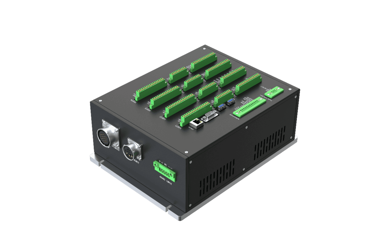
6.2 Important Safety Instructions
| Sign | Description |
|---|---|
| 1. Ensure that the controller, teach pendant, and cables do not contact liquids. A wet controller may result in injury or death. 2. The controller and teach pendant must not be placed in dusty environments or places where humidity exceeds the equipment IP protection requirements. If conductive dust exists on site, pay special attention to protection. 3. There is dangerous voltage inside the cabinet. Non-professionals must not open the cabinet while it is energized. 4. Do not directly touch screws or other metal parts inside the controller with your hands, and never remove wiring while energized. |
| 1. A safety assessment must be performed after each robot installation, and the instructions in the safety chapter must be strictly followed. 2. The controller shall be placed horizontally on the floor. A clearance of 50mm shall be reserved on each side of the controller to ensure ventilation and heat dissipation. 3. The teach pendant may be hung on the controller. Ensure that cables do not trip personnel. 4. If non-AUBO original matching components, such as cables, are added to the robot, the user must ensure that such components do not interfere with or damage equipment safety functions. 5. The software in the robot system supports only upgrades and use of the default software. Installing other software systems, such as ROS, is prohibited. Check before use: 1. Check that the controller power cable is connected properly. 2. Check that the controller and robot are connected properly. 3. Check that the controller support is stable and that the whole machine is placed horizontally without shaking or displacement. |
6.3 Introduction to Controller Panels
6.3.1 Front Panel of the Controller
The structure of the controller front panel is shown below: 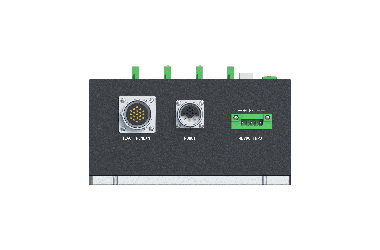
| No. | Name | Function |
|---|---|---|
| 1 | TEACH PENDANT | Teach pendant cable socket, used to connect the teach pendant cable. |
| 2 | ROBOT | Robot arm cable socket, used to connect the robot body cable. |
| 3 | 48VDC INPUT | DC48V power port. |
6.3.2 Top Panel of the Controller
The controller panel has ports for connecting external equipment, as shown below: 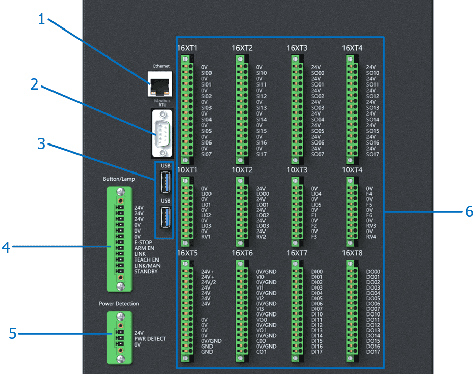
| No. | Interface | Function |
|---|---|---|
| 1 | Ethernet Interface | Ethernet interface, used for remote access and control. |
| 2 | Modbus RTU Interface | Can be connected to Modbus devices. |
| 3 | USB Interface | Can be used to update software and import/export project files. |
| 4 | Button/Lamp Interface | E-STOP emergency stop indicator, ARM EN arm enable indicator, LINK linkage indicator, TEACH EN teach pendant enable button, LINK/MAN linkage/manual working mode selection button, and STANDBY standby indicator. |
| 5 | Power Detection Interface | Interface for connecting the power failure detection module. |
| 6 | External Electrical Interface | Provides external I/O interfaces. |
6.4 Robot Cable Connection
First unscrew the dust cap from the socket on the controller interface, and then insert the robot cable plug into the controller. Pay attention to the insertion direction, and tighten the locking ring after the plug is fully inserted. 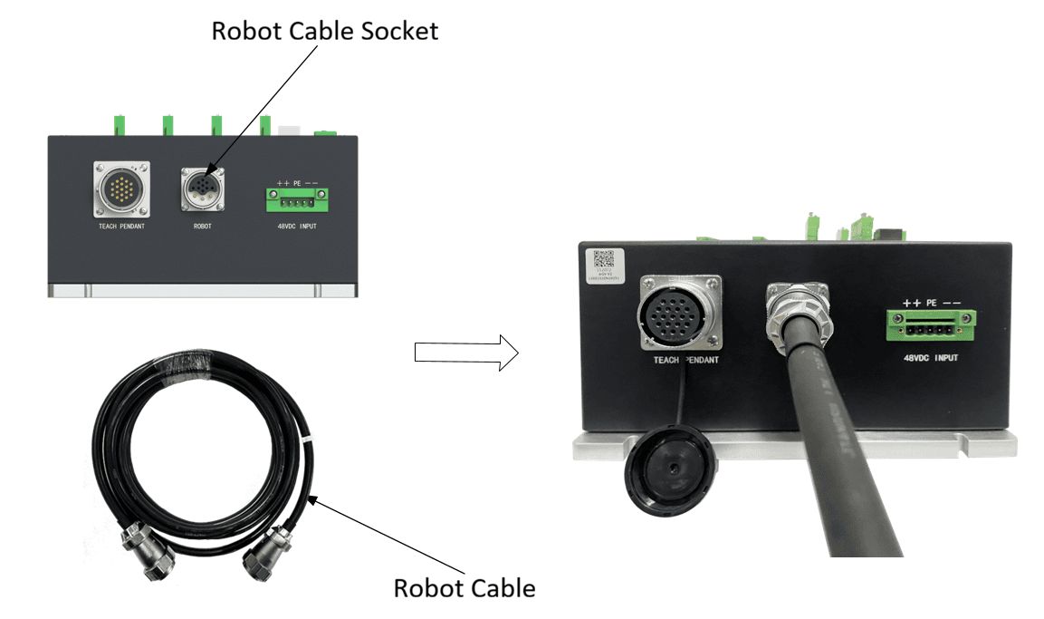
Insert the teach pendant cable plug into the teach pendant aviation socket, as shown below. Pay attention to the insertion direction, and tighten the locking ring after inserting it firmly. 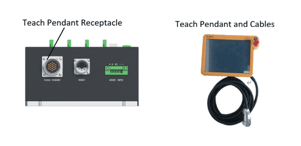
6.5 Button/Lamp Port Connection: Button/Lamp
The example configuration uses self-locking illuminated buttons. You can configure buttons and indicators according to the example, or configure independent buttons and indicators by yourself. Be sure to ensure correct wiring. 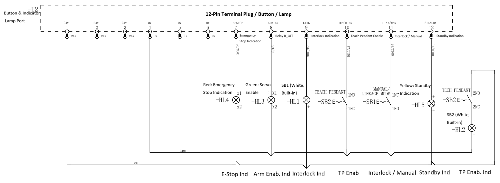
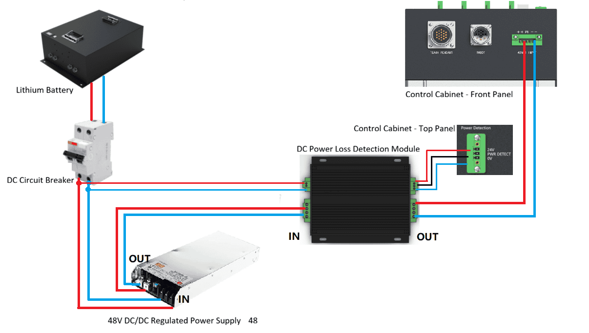
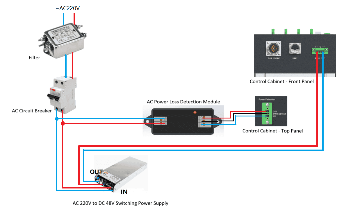
6.6 Power Supply Wiring and Power Failure Detection
- The wiring example for DC48V power supply is as follows (Note: Please wire according to the actual components):
- The wiring example for AC220V power supply is as follows (Note: Please wire according to the actual components):
6.7 Power-On
- Place the controller in a suitable position.
- Connect the controller cables as described in the above sections.
- Check that all controller cables are connected properly, including the teach pendant, terminal block, robot arm cable, etc.
- Connect the power cable.
- Press the power-on button on the teach pendant or enable the remote power-on signal, wait for the system to start, and then the robot arm can be powered on and operated normally.
6.8 Power-Off
- Press and hold the power-on button on the teach pendant or enable the remote power-off signal for 3 seconds, then disconnect the signal. The controller performs power-off operation. Power-off is prohibited while the robot is running.
- Disconnect the power cable.
| Sign | Description |
|---|---|
| Pulling the power cable directly from the socket to shut down the system may damage the machine file system and cause machine function faults. |
7 Electrical Interfaces
7.1 Electrical Warnings and Cautions
When designing and installing robot and AUBO-CB-AGV-V2 controller applications, the following warnings and cautions must be followed. These warnings and cautions must also be followed during maintenance operations.
| Sign | Description |
|---|---|
| 1. Do not connect safety signals to non-safety PLCs with unsuitable safety levels. Failure to follow this warning may result in serious injury or death due to failure of a safety stop function. 2. The controller must be powered off when wiring the controller electrical interfaces. 3. All safety signals have dual-circuit safety channels (redundant design). Keeping the two channels independent ensures that the safety function is not lost in the event of a single fault. |
| 1. Ensure that all equipment that must not get wet remains dry. If water enters the product, cut off the power supply and contact your supplier. 2. Use only the original cables of this robot. Do not use the robot in applications where those cables need to be bent. If longer cables or flexible cables are required, contact your supplier. 3. All GND terminals mentioned in this document apply only to power supply and signal transmission. For protective earth (PE), use the screw terminal marked with the grounding symbol in the controller. The grounding connector shall have at least the rated current of the highest current in the system. 4. Be careful when installing I/O interface cables for the robot. |
| 1. This robot has passed the tests specified in the international IEC standard for electromagnetic compatibility (EMC). Interference signals higher than the levels specified in the IEC standard may cause abnormal robot behavior. Extremely high signal levels or excessive exposure may cause permanent damage to the robot. EMC problems usually occur during welding and are usually indicated by error messages in the log. AUBO (Beijing) Intelligent Technology Co., Ltd. shall not be liable for any losses caused by EMC problems. 2. I/O cables used to connect the controller with other machinery and factory equipment shall not exceed 30 meters unless extension testing shows feasibility. |
- Controller communication interfaces The AUBO robot controller provides multiple electrical interfaces for connecting external devices. Users can conveniently use these interfaces.
The controller top panel provides Ethernet interface, Modbus RTU interface, USB interface, and some electrical interfaces. See 6.3.2 Top Panel of the Controller.
Ethernet Interface
The Ethernet interface can be used for remote access and control.
Modbus Device Interface
The Modbus device interface is located on the controller top panel (see 6.3.2 Top Panel of the Controller). Modbus devices can be connected through the USB interface and Modbus RTU interface.
The pin description of the Modbus RTU interface is shown below: 
USB Interface
The USB interface is located on the controller top panel (see 6.3 Introduction to Controller Panels) and can be used for device connection, software upgrade, and project file export.
- Controller I/O power supply
- Internal power supply The controller panel I/O selects internal power supply by default, as shown below:

- External power supply If users need to use an external power supply, use the following wiring method.
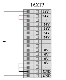
| Sign | Description |
|---|---|
| The controller must be powered off when wiring the controller electrical interfaces. |
7.2 Controller Fixed Function I/O
7.2.1 Function Definition
The AUBO-CB-AGV-V2 controller provides 6 fixed-function digital input interfaces and 4 fixed-function digital output interfaces. For details about the fixed functions, refer to the software user manual.
| Input | Interface Type | Function Definition |
|---|---|---|
| LI00 | NPN | Start program |
| LI01 | NPN | Stop program |
| LI02 | NPN | Pause program |
| LI03 | NPN | No function |
| LI04 | NPN | Remote power-on |
| LI05 | NPN | Remote power-off |
| F6 | NPN | Clear alarm signal |
| Output | Interface Type | Function Definition |
| LO00 | NPN | Low when program stops. In linkage mode, it is set to logic low when program execution is completed or terminated. |
| LO01 | NPN | High when program stops. In linkage mode, it is set to logic high when program execution is completed or terminated. |
| LO02 | NPN | Program paused. In linkage mode, it is set to logic high when the program is paused. |
| LO03 | NPN | Function 1: Reached home position. In linkage mode, it is set to logic high when the robot arm joint-space position reaches the home position. Function 2: Handle function - green indicator. Note: Function 1 is the default. After the handle control function is enabled, it switches to Function 2. |
7.2.2 Remote Power-On
Using the remote power-on/off control I/O interface, the teach pendant and robot body can be turned on or off without using the teach pendant.
This example describes how to connect the remote power-on interface. As shown in the figure, after the switch is closed for 1s, the teach pendant powers on. After entering the system, the robot arm can be controlled normally. 
7.2.3 Remote Power-Off
This example describes how to connect the remote power-off interface. As shown in the figure, after the switch is closed for 3s, the robot arm powers off and the teach pendant shuts down. 
7.3 Controller Configurable I/O
The AUBO-CB-AGV-V2 controller provides 16 configurable digital input interfaces and 16 configurable digital output interfaces. Configurable I/O has dual-circuit safety channels, which ensures that the safety function is not lost in the event of a single fault. During use, safety devices and equipment must be installed according to safety instructions and may be used only after a comprehensive risk assessment.
Configurable I/O can be used as safety I/O only after being configured in the teach pendant software. If not configured, it is used as general digital I/O of the controller. Safety I/O has higher priority than general I/O. That is, when the same I/O is configured as both safety I/O and general I/O, only the safety I/O function is retained. For specific functions and descriptions of safety I/O, refer to the software user manual.
| Input/Output | Interface Type | Function Definition |
|---|---|---|
| SI00-SI07 | NPN | Set specific functions through the software interface |
| SI10-SI17 | NPN | |
| SO00-SO07 | NPN | Set specific functions through the software interface |
| SO10-SO17 | NPN | |
7.4 Controller General I/O
7.4.1 Function Definition
The AUBO-CB-AGV-V2 controller provides 4 general analog input interfaces, 2 general analog voltage output interfaces, 2 general analog current output interfaces, 16 general digital input interfaces, and 16 general digital output interfaces, with electrical error within ±1%. The functions of general I/O must be configured in the teach pendant software. For specific functions and descriptions, refer to the software user manual.
| Input/Output | Interface Type | Function Definition |
|---|---|---|
| DI00-DI07 | NPN | Set specific functions through the software interface |
| DI10-DI17 | NPN | |
| DO00-DO07 | NPN | |
| DO10-DO17 | NPN | |
| VI0-VI3 | NPN | Set specific functions through the software interface |
| VO0-VO1 | NPN | |
| CO0-CO1 | NPN |
| Sign | Description |
|---|---|
| When connecting external equipment, all external equipment must share ground with the controller. |
7.4.2 Digital I/O Interface
The general digital input terminals (DI terminals) on the AUBO-CB-AGV-V2 controller all operate in NPN mode. That is, a DI terminal is triggered when it conducts to ground, and it is not triggered when it is disconnected from ground.
DI terminals can read action signals from switch buttons, sensors, PLCs, or other AUBO robots.
The general digital output terminals (DO terminals) on the AUBO-CB-AGV-V2 controller all operate in NPN mode. Figure 7-6 shows the working process of the DO terminal. When logic “1” is given, the DO terminal and GND conduct. When logic “0” is given, the DO terminal and GND are disconnected. 
DO terminals can be directly connected to loads, or communicate with PLCs or other robots.
| DI/DO | Parameter | Specification |
|---|---|---|
| DI | Input signal form | Sink input Voltage-free contact input NPN open-collector transistor |
| Input method | Input signal current | |
| Electrical specification | 5mA/DC24V | |
| DO | Output form | Transistor (sink type) |
| Electrical specification | 300mA/DC24V |
| Parameter Item | Minimum | Maximum |
|---|---|---|
| Input voltage of a single DI terminal | 0V | 24V |
Examples
The following lists some common wiring examples.
- DI terminal connected to a button switch As shown in Figure 7-7, a DI terminal can be connected to ground (G) through a normally open button. When the button is pressed, the DI terminal and GND conduct and trigger an action. When the button is not pressed, the DI terminal and GND are disconnected and no action is triggered. This is the simplest wiring example.

- DI terminal connected to a two-terminal sensor As shown in Figure 7-8, a sensor is connected between the DI terminal and GND. If the voltage difference between the OUT terminal and GND terminal is very small when the sensor is operating, an action can also be triggered. When the sensor is not operating, the circuit is open and no action is triggered.
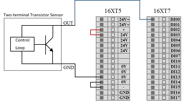
- DO terminal connected to load

7.4.3 Analog I/O Interface
The analog I/O interface is located on the rear interface board of the controller. It has 4 pairs of analog voltage input interfaces, represented by VI terminals, 2 analog voltage output terminals, and 2 analog current output terminals, represented by VO and CO respectively, as shown below.

| Type | Voltage | Current |
|---|---|---|
| Input | 0~+10V | - |
| Output | 0~+10V | 0~20mA |
| Accuracy | ±1% | ±1% |
| Parameter Item | Minimum | Maximum | Unit |
|---|---|---|---|
| Input voltage | 0 | +10 | V |
| Input resistance | 100K | Ω | |
| VI sampling resolution | 12 | BITS | |
| VI sampling accuracy | 10 | BITS | |
| Parameter Item | Minimum | Maximum | Unit |
|---|---|---|---|
| Output voltage of a single VO terminal | 0 | +10 | V |
| Output current of a single CO terminal | 0 | 20 | mA |
Examples
- Analog voltage input wiring method For analog voltage input, refer to the following external sensor wiring example.

- Analog voltage output wiring method For analog voltage output, refer to the wiring method shown below.

- Analog current output wiring method For analog current output, use the wiring method shown below.

7.5 Control Handle I/O
The AUBO-CB-AGV-V2 controller reserves 6 digital interfaces for connecting a control handle. When connecting a control handle, connect the controller to the handle adapter plate first, and then connect the control handle through the adapter plate.
7.5.1 Reserved Controller I/O Function Definition
| Input/Output | Interface Type | Function Definition |
|---|---|---|
| F1 | NPN | Handle function - power button |
| F2 | NPN | Handle function - enable button |
| F3 | NPN | Handle function - start/stop button |
| F4 | NPN | Handle function - custom button |
| F5 | NPN | Handle function - emergency stop button |
| LO03 | NPN | Handle function - green indicator, valid only when the control handle function is enabled |
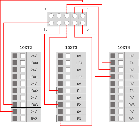
7.5.2 Handle Adapter Plate Connection
The AUBO-CB-AGV-V2 controller must be connected to the control handle through the control handle adapter plate. The pin description and wiring diagram of the control handle adapter plate are shown below. 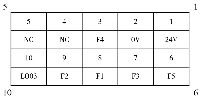
8 Appendix
8.1 Glossary
Category 0 stop: Uncontrolled stop, the power is cut off immediately and the joint brakes are applied without controlled deceleration, so the robot may deviate from the programmed path. It applies only to extreme cases such as exceeding the safety-rated limit or a failure in the safety-rated part of the control system. For the definitions of stop categories and the requirement to remove power immediately, refer to IEC 60204-1:2016 (9.2.2 Stop categories); for the design requirements of the emergency stop function, refer to EN ISO 13850:2015.
Category 1 stop: Controlled stop with power removed afterwards, the robot stops along the programmed path and the power is removed once the stop is achieved, balancing safety and path stability. For the definitions of stop categories and the requirement to remove power after the stop, refer to IEC 60204-1:2016 (9.2.2 Stop categories); for the design requirements of the emergency stop function, refer to EN ISO 13850:2015.
Category 2 stop: Controlled stop with power maintained, the robot remains powered after it stops, and the safety-rated control system holds it in the stopped position so that work can be resumed quickly. For the definitions of stop categories and the requirement to maintain power, refer to IEC 60204-1:2016 (9.2.2 Stop categories). A category 2 stop must not be used as an emergency stop, and is therefore not covered by EN ISO 13850:2015.
8.2 Technical Specifications
| Controller Model | AUBO-CB-AGV-V2 | |
|---|---|---|
| IP Protection Rating | IP43 | |
| Controller Dimensions (L*H*W) | 310 mm * 230 mm * 125.5 mm | |
| Controller Weight | 8.5 kg | |
| I/O Ports | Digital input | 16 (general) / 16 (configurable) |
| Digital output | 16 (general) / 16 (configurable) | |
| Analog input | 4 | |
| Analog output | 4 | |
| I/O Power Supply | 24V 3A | |
| Communication Protocols | Ethernet, Modbus-RTU/TCP, Profinet (optional) | |
| Interfaces and Openness | SDK (supports C/C++/C#/Lua/Python development), supports ROS system, API | |
| Operating Temperature | 0°C~50°C | |
| Transportation and Storage Temperature | -25°C~55°C | |
| Humidity | 90% relative humidity (non-condensing) | |
| Power Supply | DC48V | |
| Cables | Cable connecting robot arm and controller (5m) Cable connecting teach pendant and controller (4m) | |
8.3 Revision Records
| Version//Date | Description |
|---|---|
| v1.0.0*//20251209 | Released v1.0.0* trial version. |
| v1.0.1*//20260827 | 1. Released v1.0.1* trial version. 2. Unified manual structure, safety instructions, chapter names, and warning signs. |
| v1.0.2*//20260922 | 1. Released v1.0.2* trial version. 2. Added descriptions of stop categories in the appendix, and added the stop category description with a link to the appendix in [2.7.1 Emergency Stop Device]. |