
iS Series Pro Robot Arm User Manual
1 About This Manual
1.1 Version Information
| Item | Description |
|---|---|
| Manual name | iS Series Pro Robot Arm User Manual |
| Manual version | v1.0.3* |
| Release date | 2026-10-13 |
| Applicable products | iS3 Pro robot arm, iS7 Pro robot arm, iS10 Pro robot arm, iS16 Pro robot arm, iS20 Pro robot arm, iS20L Pro robot arm, iS25 Pro robot arm |
| Applicable controller | The iS Series Pro robot arm is compatible with the AUBO-CB-iS controller. |
This user manual is reviewed and revised periodically. Updates will be released with new versions. The content or information in this manual is subject to change without prior notice.
Before installing or using the product, read this manual thoroughly and keep it available for future reference.
All images in this manual are for illustrative reference only. The actual product shall prevail.
1.2 Copyright and Disclaimer
This manual is proprietary to AUBO (Beijing) Intelligent Technology Co., Ltd. Without the written permission of AUBO (Beijing) Intelligent Technology Co., Ltd., it may not be photocopied, reproduced in whole or in part, or converted into any other format.
AUBO (Beijing) Intelligent Technology Co., Ltd. shall not be liable for any errors or omissions that may appear in this manual, or for incidental or consequential injury or damage arising from the use of this manual and the products described herein.
Copyright © 2015-2026 AUBO. All rights reserved.
1.3 Purpose of This Manual
This manual provides guidance for installation, commissioning, pre-operation inspection, maintenance, repair, handling, storage, and disposal of the iS Series Pro robot arm.
This manual does not replace the system integrator's risk assessment, on-site safety design, operating instructions, or applicable laws, regulations, and safety standards of the country or region where the robot system is used.
1.4 Target Audience
This manual is intended for the following qualified personnel:
- Robot arm installation personnel
- Commissioning and operating personnel
- Maintenance and repair personnel
- Safety management personnel
1.5 Operation Prerequisites
Personnel who read and use this manual must meet the following requirements:
- Have received relevant training provided by AUBO or an AUBO-authorized distributor;
- Possess basic knowledge required for installation and maintenance of mechanical, electrical, and automation equipment;
- Be familiar with on-site safety management requirements and have basic risk identification and safe operating practices;
- Have read and understood the safety instructions in this manual and related documents.
1.6 Related Documents
When using this manual, it is recommended to also read the following documents:
1.7 More Information
For more information about products, services, training, or technical support, visit https://www.aubo-robotics.com.
2 Safety
2.1 Safety Instructions
This chapter describes the fundamental safety principles that must be observed when operating the robot arm or robot system. Integrators, users, and operators must read this chapter carefully and strictly follow the instructions marked with safety warning symbols.
Because robot systems are complex and potentially hazardous, this manual cannot list every possible hazardous scenario. Users and integrators shall perform risk assessment according to the actual application, end effectors, peripheral equipment, working environment, and personnel activity range, and shall take appropriate risk-reduction measures.
2.2 Safety Warning Symbols
This manual uses the following safety warning symbols to identify important safety information. When these symbols are encountered, read and follow the corresponding instructions carefully.
| Symbol | Level | Description |
|---|---|---|
 | DANGER | Indicates a potentially hazardous situation which, if not avoided, could result in death or serious injury. |
 | WARNING | Indicates a potentially hazardous situation which, if not avoided, could result in personal injury or serious equipment damage. |
 | CAUTION | Indicates a potentially hazardous situation which, if not avoided, could result in minor personal injury or equipment damage. Matters marked with this symbol may, depending on circumstances, have the potential for serious consequences. |
 | NOTICE | Indicates a situation which, if not avoided, could result in personal injury or equipment damage. Matters marked with this symbol may, depending on circumstances, have the potential for serious consequences. |
2.3 General Safety Requirements
When operating the robot arm and related equipment, always observe the following basic safety requirements. This section lists general safety requirements; safety instructions for specific scenarios are provided in the relevant chapters of this manual.
- Install the robot and all electrical equipment strictly in accordance with the requirements and specifications in this manual.
- Before first use and before putting the robot into production, perform initial tests and inspections on the robot and its protective system.
- Before starting the robot and system for the first time, check that the robot and system are complete, safe to operate, and free of damage. During this inspection, verify compliance with valid national or regional production safety regulations and test all safety functions.
- The user must check and ensure that all safety parameters and user programs are correct and that all safety functions operate properly. Each safety function must be checked by personnel qualified to operate the robot. The robot may only be started after comprehensive and careful safety testing confirms that the required safety level has been reached.
- Installation and commissioning must be performed by qualified professionals in accordance with installation standards.
- After installation and construction are complete, perform a comprehensive risk assessment again and keep documented records.
- Safety parameters must be set and changed only by authorized personnel. Passwords or isolation measures must be used to prevent unauthorized modification or setting of safety parameters. After safety parameters are changed, the related safety functions must be analyzed.
- In the event of an accident or abnormal operation, the emergency stop switch may be used to stop robot motion.
- The robot arm is equipped with collision detection. When the powered robot is subjected to external force exceeding the normal force range set by the user for safety, the robot stops automatically to prevent collision injury to the operator or damage to the robot. This function is specifically designed for human-robot collaboration safety on the iS Series Pro robot arm, but it requires the robot system to operate within its normal operating range and to use an AUBO series controller. If the user develops a controller independently, the robot will not have the above function, and the user shall bear all resulting hazardous consequences.
- Connecting different machines may increase hazards or create new hazards. Always perform a comprehensive risk assessment for the entire installation. When different safety and emergency-stop performance levels are required, always select the highest performance level.
- AUBO (Beijing) Intelligent Technology Co., Ltd. shall not be liable for machine damage or personal injury caused by improper operation of the robot.
Strictly prohibited actions:
| Symbol | Description |
|---|---|
| 1. Do not start the robot arm before completing safety inspection and risk assessment. Before first startup, the following checks must be completed: - System integrity inspection (mechanical installation, electrical connection, and protective grounding) - All safety function tests - Safety parameter correctness verification - Risk assessment documentation review 2. Do not power on the robot arm without connecting the protective earth conductor (PE conductor). Poor grounding may cause electric shock, equipment damage, or electromagnetic interference. 3. Do not use the controller in humid environments or environments with conductive dust, as this may result in injury or death. 4. Do not manually and frequently switch the power supply system on and off. The robot arm joint modules are equipped with brakes to maintain robot posture when power is off. Avoid frequent power cycling; it is recommended that each power on/off interval be greater than 10 s. 5. Do not touch joint or motor surfaces while the robot arm is operating. Do not operate or touch the robot while it is working or immediately after it stops. Disconnect power and wait one hour for the robot to cool down. 6. Do not modify safety parameters or bypass safety functions without authorization. |
Operating requirements:
| Symbol | Description |
|---|---|
| 1. Ensure that the robot arm and end effector are securely installed. Insecure installation may cause equipment to fall or reduce operating accuracy. 2. Ensure sufficient workspace for the robot arm, free of obstacles, sharp corners, or pinch points. Operators' heads and faces shall remain outside the robot arm's reachable range. 3. Do not connect safety devices to general-purpose I/O interfaces. Only dedicated safety interfaces may be used. 4. Correctly configure installation parameters, including installation angle, TCP weight and offset, safety parameters, etc. 5. Do not continue using a damaged robot arm. Stop the robot immediately and contact AUBO or an authorized service provider. 6. High-payload robot arms (≥20 kg) must not be handled manually and must be moved using compliant dedicated lifting equipment. 7. A safety assessment must be performed after every installation to confirm that all safety functions are normal. |
| 1. Before transporting the robot arm, check insulation and protective measures. Handle the robot carefully during transportation and avoid impacts. 2. Do not expose the robot arm to strong magnetic fields for extended periods. Strong magnetic fields may damage the equipment. 3. Do not modify the robot arm without authorization. Any unauthorized modification will void the warranty, and AUBO assumes no liability for any consequences arising therefrom. |
2.4 Personnel Safety
When operating the robot system, personnel safety shall be the first priority. Users and integrators shall at least take the following measures:
- Ensure that all relevant personnel have received official AUBO training or training from an AUBO-authorized distributor, and fully understand safe and standardized operating procedures. For training consultation, contact support@aubo-robotics.cn.
- During operation, tie back long hair, do not wear loose clothing, and do not wear jewelry. When stationary, the robot may be waiting for a start command and shall be regarded as continuously active; approaching the robot casually is strictly prohibited.
- In emergencies where a person is trapped or confined, the robot arm may be pushed or pulled firmly to force joint movement. Manual movement of the robot arm without power is limited to emergencies and may damage the robot arm joints.
- Personnel shall not place the head, face, neck, fingers, or other body parts in areas where collision, pinching, or entanglement may occur.
2.5 Responsibilities and Standards
The robot arm is a component of a complete robot system and is not a complete machine by itself. Therefore, this manual does not cover the full design, installation, and operation solution for the complete robot system, nor does it list all risk conditions related to peripheral equipment that may affect the safety of the integrated system. The installation safety performance of complete robot equipment depends on the design and construction of the overall integration solution. The equipment integrator shall conduct a risk assessment throughout the design and installation process of the complete integrated system in accordance with applicable local laws, regulations, safety codes, and industry standards.
All safety information contained in this manual shall not be regarded as a guarantee by AUBO (Beijing) Intelligent Technology Co., Ltd. Even if operators strictly follow all safety instructions in this manual, potential risks of personal injury or equipment damage may still exist.
AUBO (Beijing) Intelligent Technology Co., Ltd. continuously optimizes product performance and reliability and reserves the right to upgrade products without prior notice. AUBO has made every effort to ensure that the content of this manual is accurate and reliable, but assumes no responsibility for omissions or errors in the document.
2.5.1 Integrator Responsibilities
The integrator assumes the following key responsibilities:
- Conduct a comprehensive risk assessment of the complete robot system;
- Ensure that the design, installation, and commissioning of the complete system meet safety requirements;
- Provide necessary training to users and relevant operators;
- Develop complete system operating procedures and emergency response plans;
- Establish and maintain appropriate safety protection measures;
- Use appropriate methods during final installation to eliminate hazards or reduce all hazards to an acceptable level;
- Inform the end user of residual risks;
- Mark integrator information on the robot;
- Archive all relevant technical documents and risk assessment reports.
2.5.2 Reference Standards
The integrator may refer to the following international standards when performing the risk assessment process:
| Standard No. | Title | Description |
|---|---|---|
| ISO 12100:2010 | Safety of machinery — General principles for design — Risk assessment and risk reduction | Basic risk assessment framework |
| ISO 10218-2:2025 | Robots and robotic devices — Safety requirements — Part 2: Industrial robot systems and robot applications | Safety requirements for industrial robot integration |
| RIA TR R15.306-2014 | Technical Report for Industrial Robots and Robot Systems — Safety Requirements, Task-Based Risk Assessment Methodology | Task-based risk assessment guidance |
| ANSI B11.0-2010 | Safety of Machinery — General Requirements and Risk Assessment | U.S. machinery safety standard |
For applicable standards and regulatory guidance, visit the AUBO website at www.aubo-robotics.com or consult local regulatory authorities.
2.6 Hazard Identification
Risk assessment shall consider potential hazards during normal use, commissioning, maintenance, cleaning, abnormal recovery, and foreseeable misuse. When collaborative robot arms are used without peripheral safety guards, the following potential hazards may be involved:
- Puncture or cutting risks caused by sharp end effectors or tool connectors.
- Exposure risks when handling toxic, corrosive, or other hazardous substances.
- Risk of operator fingers or limbs being pinched by robot arm joints or the base.
- Risk of collision between the robot arm and personnel during motion.
- Risk of falling objects due to improper fixation of end effectors.
- Hazards caused by impact between the robot payload and a rigid surface. The integrator must evaluate such hazards and their associated risk levels through risk assessment, and determine and implement corresponding measures to reduce the risk to an acceptable level. Note that other significant hazards may exist for specific robot equipment.
By combining the inherent safety design of AUBO robots with the safety specifications and risk assessments developed by the integrator and end user, risks associated with collaborative operation of the robot arm can be reduced to a reasonably practicable level. This document is intended to communicate residual risks present before robot installation to the integrator and final user. If the integrator's risk assessment determines that the corresponding application scenario contains hazards that pose unacceptable risks to operators, the integrator must take appropriate risk-reduction measures to eliminate or minimize those hazards until the risk level reaches an acceptable standard. Use of the robot is prohibited before the necessary risk-reduction measures have been completed.
If the robot is deployed in a non-collaborative application, such as with hazardous tools, the risk assessment may require the integrator to add safety equipment, such as safety start devices, during program development to ensure personnel and equipment safety.
2.7 Emergency Handling
2.7.1 Emergency Stop Device
Pressing the emergency stop button immediately stops all robot motion. The robot arm itself is not equipped with a push-button emergency stop device, but push-button emergency stop devices are provided on the controller, wired teaching pendant, control handle, and other devices. For details, refer to the applicable controller user manual or accessory user manual.
| Symbol | Description |
|---|---|
| 1. Emergency stop shall not be used as a routine risk-reduction measure and shall be regarded as a secondary protective means. 2. If multiple emergency stop buttons must be connected, they must be included in the risk assessment of the robot application. 3. If an end effector poses a potential threat, it must be integrated into the system emergency stop circuit. Failure to comply with this warning may result in death, serious personal injury, or major property damage. 4. Before releasing the emergency stop, confirm that all hazards have been completely eliminated. |
| Pressing the emergency stop button triggers a Category 1 stop. For descriptions of stop categories, see Appendix. |
2.7.2 Emergency Joint Movement
In emergencies, the robot arm joints may be moved as follows:
- Forced dragging: Push or pull the robot arm joint firmly to force the joint to move.
| Symbol | Description |
|---|---|
| Forced manual movement of the robot arm is limited to emergencies and may damage robot arm joints. |
2.7.3 Excessive Force Protection
The robot arm is equipped with excessive force protection. When the robot arm is powered on and stationary, if an operator or another object accidentally contacts the robot arm and the collision force exceeds the safety threshold, the robot arm passively moves in the direction of the collision force. This function helps reduce injury to personnel and damage to other objects and the robot arm in the event of collision.
| Symbol | Description |
|---|---|
| This function can reduce collision injury or damage. A risk assessment is required if it is used for other purposes. |
2.7.4 Collision Protection
The robot arm is equipped with collision protection. During robot operation, if an operator or another object accidentally contacts the robot arm and the collision force exceeds the safety threshold, the robot arm enters a Category 2 stop state and simultaneously enters hand-guiding mode. The robot arm can then be dragged to a relatively safe position, after which operation may be resumed through the teaching pendant. This function helps reduce injury to personnel and damage to other objects and the robot arm, while saving program restart time and improving efficiency. The collision-force safety threshold can be changed by setting the collision level.
3 Robot Arm Description
3.1 About the iS Series Pro
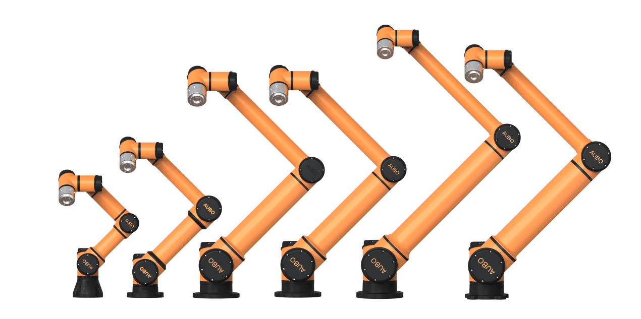
The iS Series Pro collaborative robot is a benchmark product designed for complex operating conditions across industries. It comes standard with an entry-level integrated six-axis force sensor and supports optional high-performance force control. It requires no external interfaces, features comprehensive core hardware upgrades, delivers industry-leading performance, and can be widely used across industrial applications.
The robot features a built-in high-precision six-axis force sensor. Force control repeatability can reach up to 0.1% FS, and resolution can reach up to 0.03% FS. Maximum TCP linear speed can reach up to 6.3 m/s. With a lightweight high-performance body, payload-to-weight ratio of up to 1:3, and a new generation of self-developed control algorithms, the robot provides more accurate motion control and faster response. Dedicated versions for medical, explosion-proof, welding, palletizing, and integrated vision applications can also be expanded, making it suitable for force control applications, precision manufacturing, spraying, demanding and sensitive environments, and other special scenarios.
| Symbol | Description |
|---|---|
| The iS Series Pro robot arm is compatible with the AUBO-CB-iS controller. |
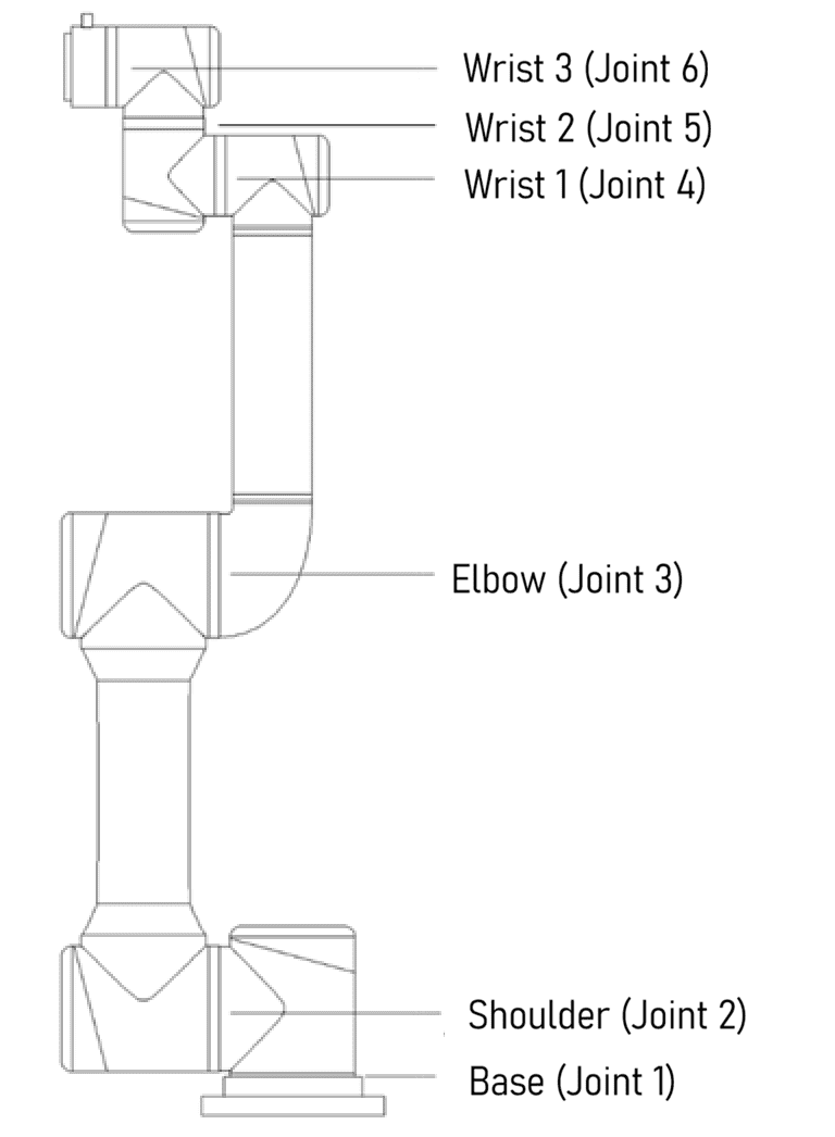
The iS Series Pro robot arm mimics the human arm and has six rotary joints, each representing one degree of freedom. As shown in Figure 3-2, the robot arm joints include the base (Joint 1), shoulder (Joint 2), elbow (Joint 3), wrist 1 (Joint 4), wrist 2 (Joint 5), and wrist 3 (Joint 6).
- The base connects the robot arm body to the base structure, and the tool flange connects the robot arm to the tool. The tool flange is located at the end of Wrist 3.
- Arm tubes connect the shoulder and elbow, and the elbow and wrist.
- Through the teaching software interface or hand-guided teaching, users can control each joint to rotate and move the robot end effector to different poses.
3.2 Technical Specifications
3.2.1 iS3 Pro
- Technical specifications of the robot arm body
| Robot arm type | iS3 Pro |
|---|---|
| Degrees of freedom | 6 rotary joints |
| Weight | 16 kg |
| Payload | 3 kg |
| Maximum working radius | 625 mm |
| Joint range | joint1/joint2/joint4/joint5/joint6: ±360° joint3: ±156° |
| Maximum joint speed | joint1/joint2/joint3/joint4/joint5/joint6: 237°/s |
| Tool speed | ≤ 2.5 m/s |
| Repeatability | ±0.02 mm |
| Operating ambient temperature range | 0 °C to 50 °C |
| Operating ambient humidity | 90% RH (non-condensing) |
| IP rating | IP66 |
| Average power | Approx. 150 W when running typical programs |
| Peak power | 1000 W |
| Mounting surface diameter | ø140 mm |
- Force control end technical specifications
| Robot arm type | iS3 Pro | |
|---|---|---|
| Parameter | Factory default | Custom configuration |
| Force range (Fz=Fx=Fy) | 150 N | - |
| Torque range (Mx=My=Mz) | 15 N·m | - |
| Overload level | 500% (750 N, 75 N·m) | - |
| Repeatability | 0.75 N, 0.075 N·m (0.5%) | 0.15 N, 0.015 N·m (0.1% FS) |
| Combined accuracy | 1.5 N, 0.15 N·m (1% FS) | 0.75 N, 0.075 N·m (0.5% FS) |
| Resolution | 0.045 N, 0.0045 N·m (0.03% FS) | - |
| IP rating | IP66 | - |
3.2.2 iS7 Pro
- Technical specifications of the robot arm body
| Robot arm type | iS7 Pro |
|---|---|
| Degrees of freedom | 6 rotary joints |
| Weight | 21.5 kg |
| Payload | 7 kg |
| Maximum working radius | 886.5 mm |
| Joint range | joint1/joint2/joint4/joint5/joint6: ±360° joint3: ±162° |
| Maximum joint speed | joint1/joint2/joint3: 237°/s joint4/joint5/joint6: 300°/s |
| Tool speed | ≤4.3 m/s |
| Repeatability | ±0.02 mm |
| Operating ambient temperature range | 0 °C to 50 °C |
| Operating ambient humidity | 90% RH (non-condensing) |
| IP rating | IP66 |
| Average power | Approx. 200 W when running typical programs |
| Peak power | 2000 W |
| Mounting surface diameter | ø170 mm |
- Force control end technical specifications
| Robot arm type | iS7 Pro | |
|---|---|---|
| Parameter | Factory default | Custom configuration |
| Force range (Fz=Fx=Fy) | 150 N | - |
| Torque range (Mx=My=Mz) | 15 N·m | - |
| Overload level | 500% (750 N, 75 N·m) | - |
| Repeatability | 0.75 N, 0.075 N·m (0.5%) | 0.15 N, 0.015 N·m (0.1% FS) |
| Combined accuracy | 1.5 N, 0.15 N·m (1% FS) | 0.75 N, 0.075 N·m (0.5% FS) |
| Resolution | 0.045 N, 0.0045 N·m (0.03% FS) | - |
| IP rating | IP66 | - |
3.2.3 iS10 Pro
- Technical specifications of the robot arm body
| Robot arm type | iS10 Pro |
|---|---|
| Degrees of freedom | 6 rotary joints |
| Weight | 36 kg |
| Payload | 12 kg |
| Maximum working radius | 1300 mm |
| Joint range | joint1/joint2/joint4/joint5/joint6: ±360° joint3: ±165° |
| Maximum joint speed | joint1/joint2: 280°/s joint3: 237°/s joint4/joint5/joint6: 300°/s |
| Tool speed | ≤6.3 m/s |
| Repeatability | ±0.03 mm |
| Operating ambient temperature range | 0 °C to 50 °C |
| Operating ambient humidity | 90% RH (non-condensing) |
| IP rating | IP66 |
| Average power | Approx. 500 W when running typical programs |
| Peak power | 2000 W |
| Mounting surface diameter | ø218 mm |
- Force control end technical specifications
| Robot arm type | iS10 Pro | |
|---|---|---|
| Parameter | Factory default | Custom configuration |
| Force range (Fz=Fx=Fy) | 300 N | - |
| Torque range (Mx=My=Mz) | 30 N·m | - |
| Overload level | 300% (900 N, 90 N·m) | - |
| Repeatability | 1.5 N, 0.15 N·m (0.5%) | 0.3 N, 0.03 N·m (0.1% FS) |
| Combined accuracy | 3 N, 0.3 N·m (1% FS) | 1.5 N, 0.15 N·m (0.5% FS) |
| Resolution | 0.09 N, 0.009 N·m (0.03% FS) | - |
| IP rating | IP66 | - |
3.2.4 iS16 Pro
- Technical specifications of the robot arm body
| Robot arm type | iS16 Pro |
|---|---|
| Degrees of freedom | 6 rotary joints |
| Weight | 64 kg |
| Payload | 16 kg |
| Maximum working radius | 1900 mm |
| Joint range | joint1/joint2/joint4/joint5/joint6: ±360° joint3: ±165° |
| Maximum joint speed | joint1/joint2: 190°/s joint3: 280°/s joint4/joint5/joint6: 300°/s |
| Tool speed | ≤6.3 m/s |
| Repeatability | ±0.05 mm |
| Operating ambient temperature range | 0 °C to 50 °C |
| Operating ambient humidity | 90% RH (non-condensing) |
| IP rating | IP66 |
| Average power | Approx. 1000 W when running typical programs |
| Peak power | 3000 W |
| Mounting surface diameter | ø260 mm |
- Force control end technical specifications
| Robot arm type | iS16 Pro | |
|---|---|---|
| Parameter | Factory default | Custom configuration |
| Force range (Fz=Fx=Fy) | 500 N | - |
| Torque range (Mx=My=Mz) | 40 N·m | - |
| Overload level | 300% (1500 N, 120 N·m) | - |
| Repeatability | 2.5 N, 0.2 N·m (0.5%) | 0.5 N, 0.04 N·m (0.1% FS) |
| Combined accuracy | 5 N, 0.4 N·m (1% FS) | 2.5 N, 0.2 N·m (0.5% FS) |
| Resolution | 0.15 N, 0.015 N·m (0.03% FS) | - |
| IP rating | IP66 | - |
3.2.5 iS20 Pro
- Technical specifications of the robot arm body
| Robot arm type | iS20 Pro |
|---|---|
| Degrees of freedom | 6 rotary joints |
| Weight | 64 kg |
| Payload | 20 kg |
| Maximum working radius | 1647 mm |
| Joint range | joint1/joint2/joint4/joint5/joint6: ±360° joint3: ±165° |
| Maximum joint speed | joint1/joint2: 190°/s joint3: 280°/s joint4/joint5/joint6: 300°/s |
| Tool speed | ≤5.4 m/s |
| Repeatability | ±0.05 mm |
| Operating ambient temperature range | 0 °C to 50 °C |
| Operating ambient humidity | 90% RH (non-condensing) |
| IP rating | IP66 |
| Average power | Approx. 1000 W when running typical programs |
| Peak power | 3000 W |
| Mounting surface diameter | ø260 mm |
- Force control end technical specifications
| Robot arm type | iS20 Pro | |
|---|---|---|
| Parameter | Factory default | Custom configuration |
| Force range (Fz=Fx=Fy) | 500 N | - |
| Torque range (Mx=My=Mz) | 40 N·m | - |
| Overload level | 300% (1500 N, 120 N·m) | - |
| Repeatability | 2.5 N, 0.2 N·m (0.5%) | 0.5 N, 0.04 N·m (0.1% FS) |
| Combined accuracy | 5 N, 0.4 N·m (1% FS) | 2.5 N, 0.2 N·m (0.5% FS) |
| Resolution | 0.15 N, 0.015 N·m (0.03% FS) | - |
| IP rating | IP66 | - |
3.2.6 iS20L Pro
- Technical specifications of the robot arm body
| Robot arm type | iS20L Pro |
|---|---|
| Degrees of freedom | 6 rotary joints |
| Weight | 72 kg |
| Payload | 20 kg |
| Maximum working radius | 2000 mm |
| Joint range | joint1/joint2/joint4/joint5/joint6: ±360° joint3: ±165° |
| Maximum joint speed | joint1/joint2: 140°/s joint3: 280°/s joint4/joint5/joint6: 300°/s |
| Tool speed | ≤4.8 m/s |
| Repeatability | ±0.05 mm |
| Operating ambient temperature range | 0 °C to 50 °C |
| Operating ambient humidity | 90% RH (non-condensing) |
| IP rating | IP66 |
| Average power | Approx. 1000 W when running typical programs |
| Peak power | 3000 W |
| Mounting surface diameter | ø282 mm |
- Force control end technical specifications
| Robot arm type | iS20L Pro | |
|---|---|---|
| Parameter | Factory default | Custom configuration |
| Force range (Fz=Fx=Fy) | 500 N | - |
| Torque range (Mx=My=Mz) | 40 N·m | - |
| Overload level | 300% (1500 N, 120 N·m) | - |
| Repeatability | 2.5 N, 0.2 N·m (0.5%) | 0.5 N, 0.04 N·m (0.1% FS) |
| Combined accuracy | 5 N, 0.4 N·m (1% FS) | 2.5 N, 0.2 N·m (0.5% FS) |
| Resolution | 0.15 N, 0.015 N·m (0.03% FS) | - |
| IP rating | IP66 | - |
3.2.7 iS25 Pro
- Technical specifications of the robot arm body
| Robot arm type | iS25 Pro |
|---|---|
| Degrees of freedom | 6 rotary joints |
| Weight | 75.6 kg |
| Payload | 25 kg |
| Maximum working radius | 1700 mm |
| Joint range | joint1/joint2/joint4/joint5/joint6: ±360° joint3: ±165° |
| Maximum joint speed | joint1/joint2: 140°/s joint3: 280°/s joint4/joint5/joint6: 300°/s |
| Tool speed | ≤4.1 m/s |
| Repeatability | ±0.05 mm |
| Operating ambient temperature range | 0 °C to 50 °C |
| Operating ambient humidity | 90% RH (non-condensing) |
| IP rating | IP66 |
| Average power | Approx. 1000 W when running typical programs |
| Peak power | 3000 W |
| Mounting surface diameter | ø282 mm |
- Force control end technical specifications
| Robot arm type | iS25 Pro | |
|---|---|---|
| Parameter | Factory default | Custom configuration |
| Force range (Fz=Fx=Fy) | 500 N | - |
| Torque range (Mx=My=Mz) | 40 N·m | - |
| Overload level | 300% (1500 N, 120 N·m) | - |
| Repeatability | 2.5 N, 0.2 N·m (0.5%) | 0.5 N, 0.04 N·m (0.1% FS) |
| Combined accuracy | 5 N, 0.4 N·m (1% FS) | 2.5 N, 0.2 N·m (0.5% FS) |
| Resolution | 0.15 N, 0.015 N·m (0.03% FS) | - |
| IP rating | IP66 | - |
3.3 Performance Parameters
3.3.1 Payload Curve
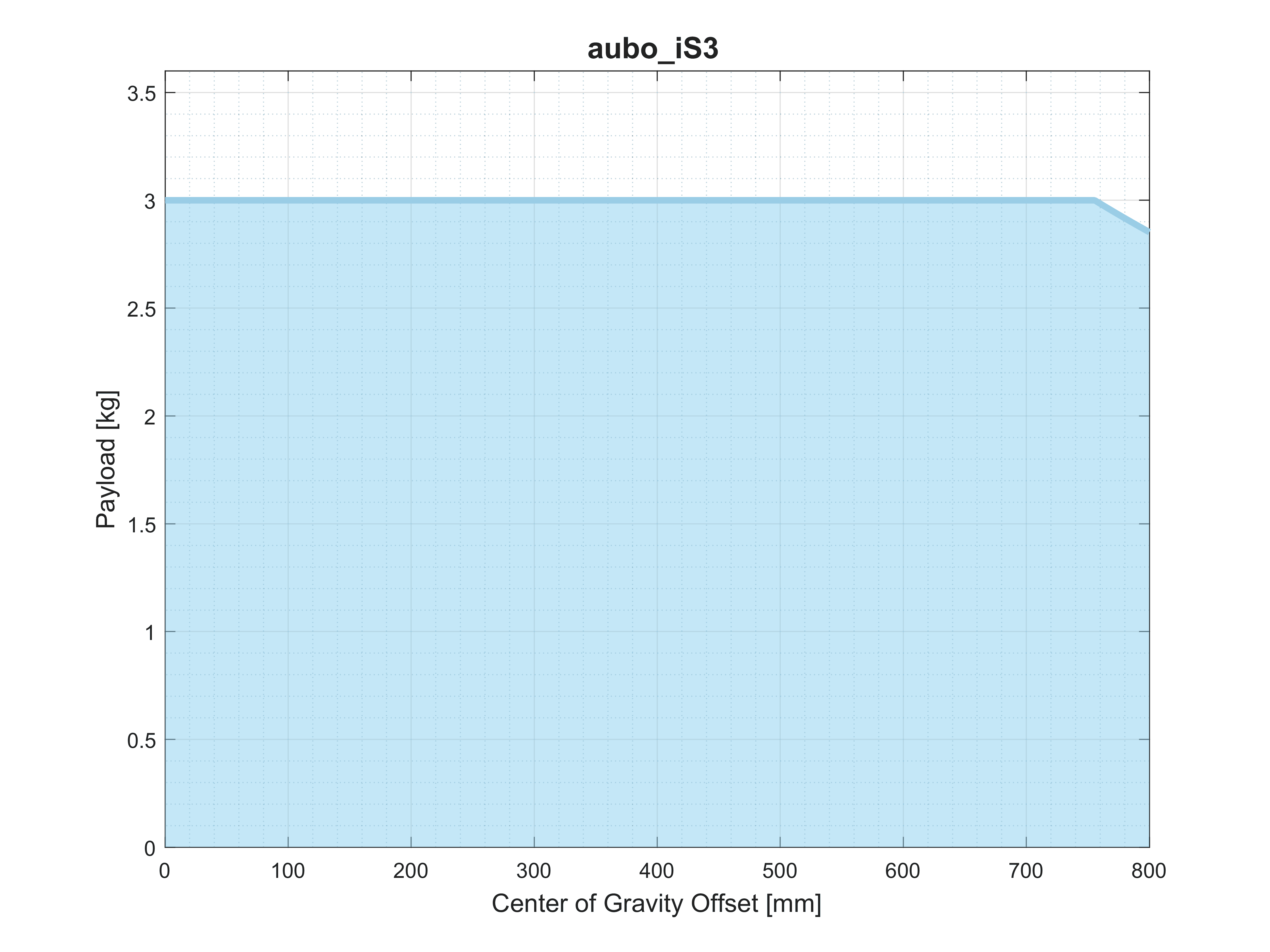
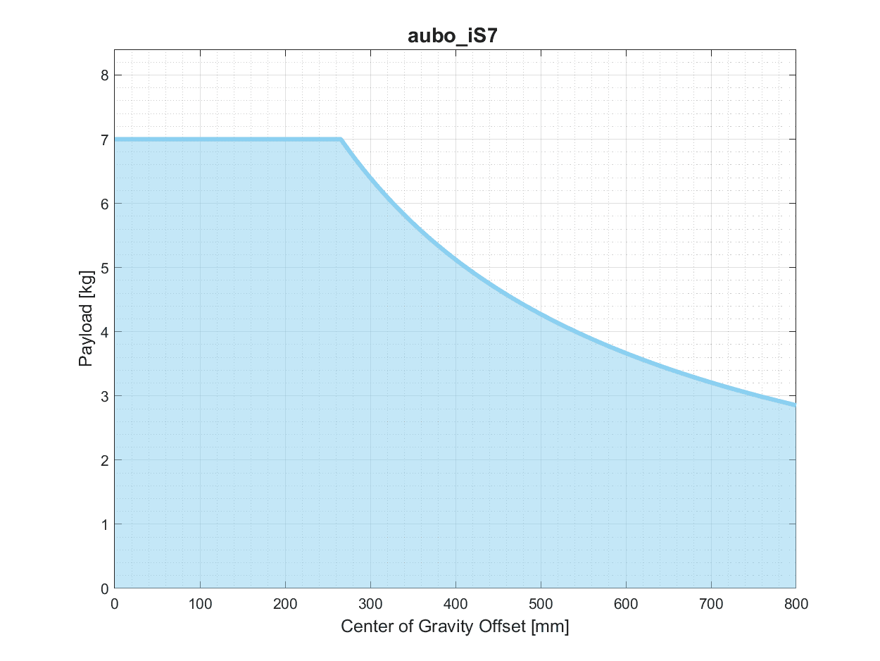
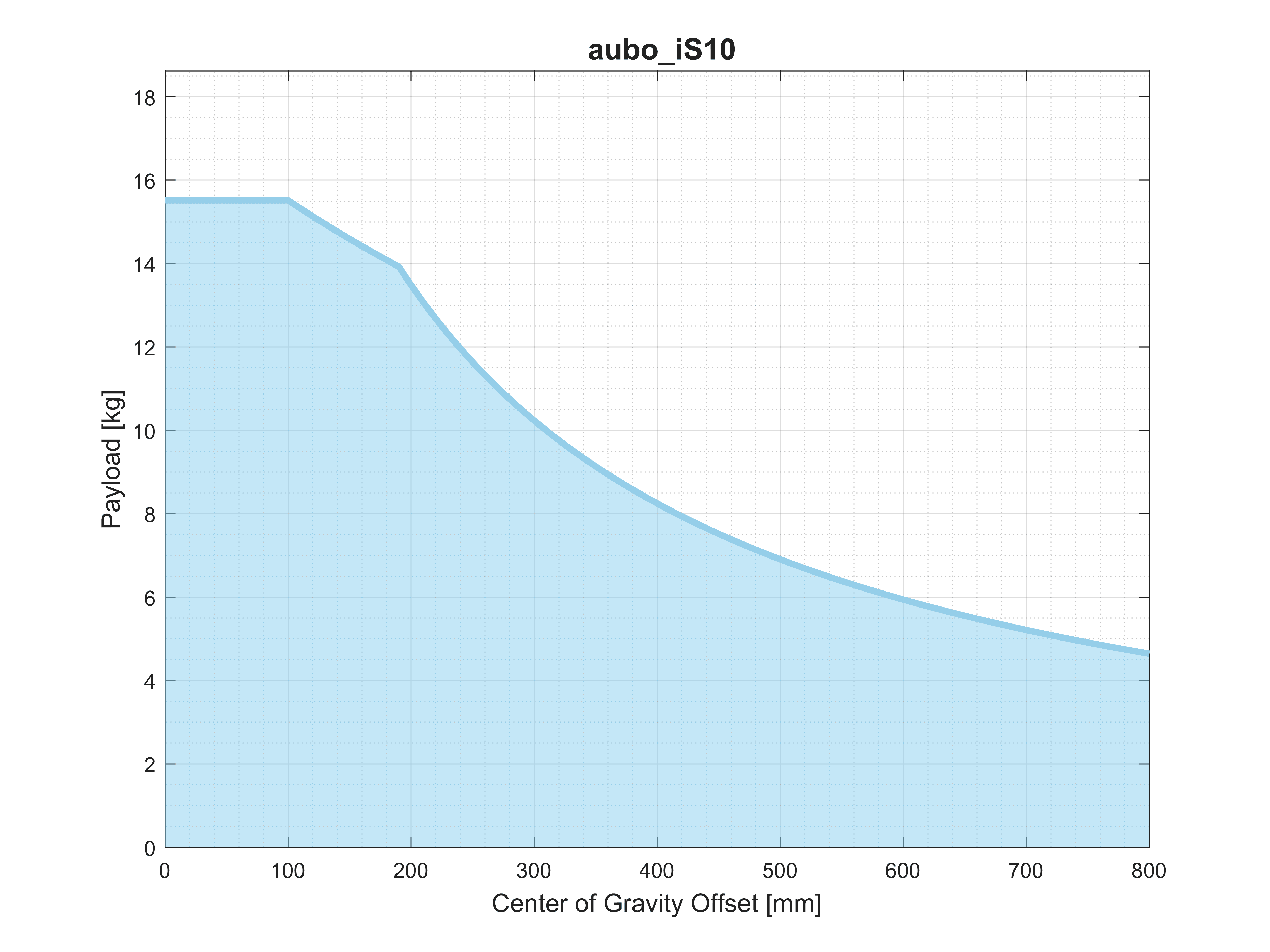
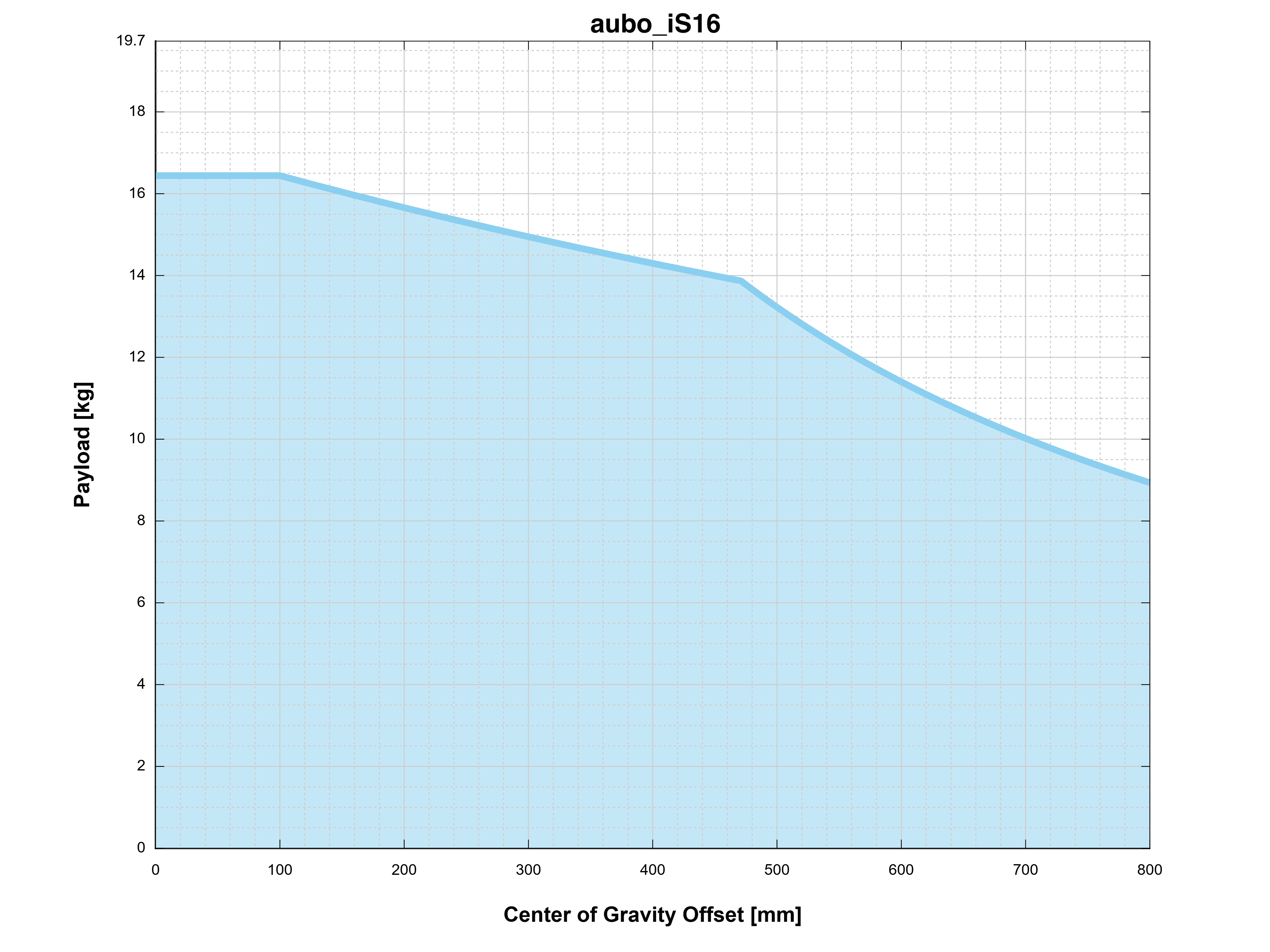
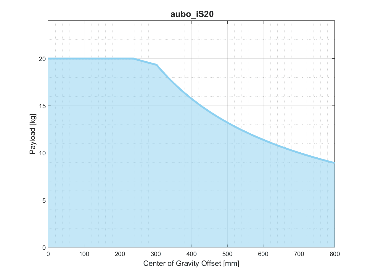
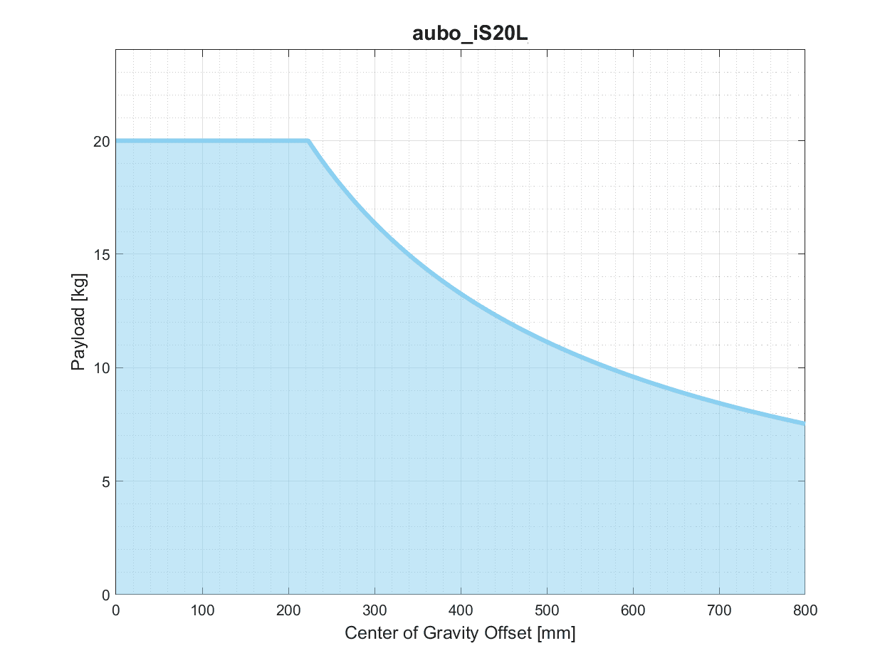
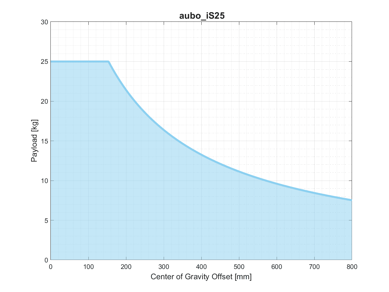
The following figures show the wrist payload offset curves of the robot arms. The vertical axis Payload indicates payload, and the horizontal axis Center of Gravity Offset indicates the distance between the center of the tool flange and the tool center of gravity.
| Symbol | Description |
|---|---|
| 1. Load conditions shall remain within the range shown in the chart. 2. The load shown in the chart is the maximum payload capacity of the corresponding robot arm model. Under no circumstances shall the maximum weight shown in the chart be exceeded. 3. Exceeding the allowable value may damage internal machine components. |
3.4 Robot Arm Workspace
3.4.1 Mechanical Dimensions
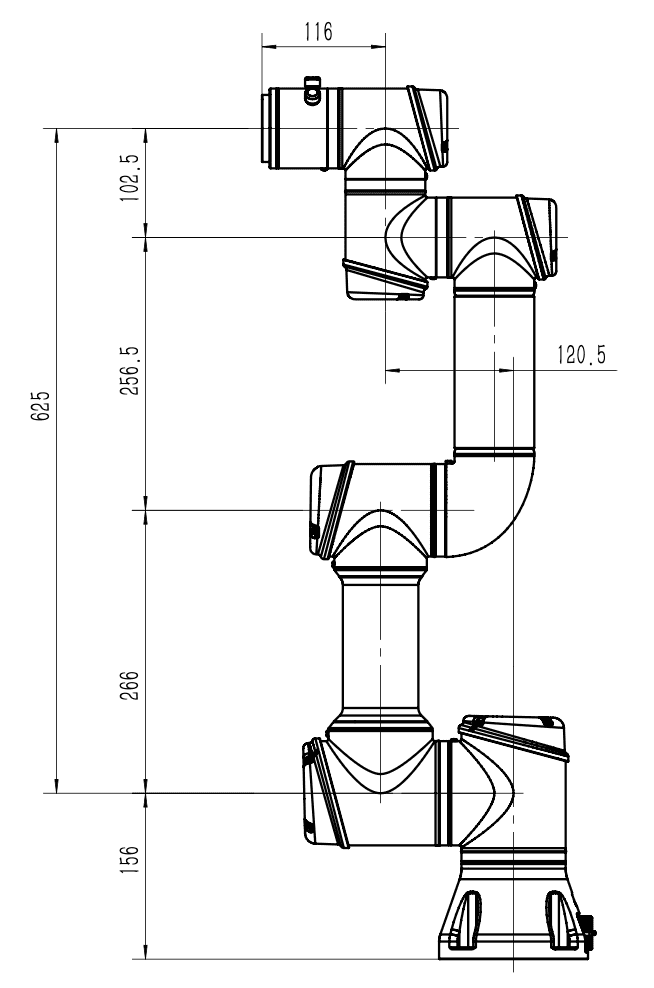
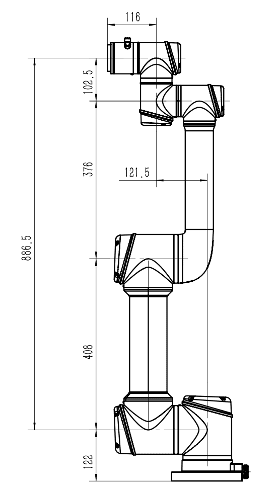
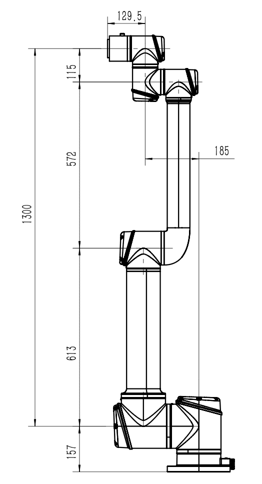
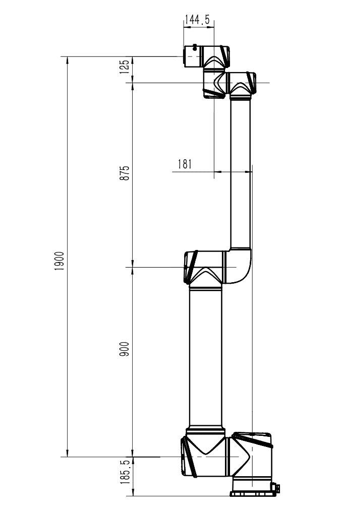
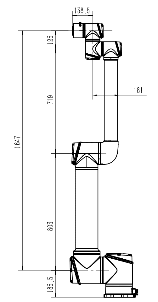
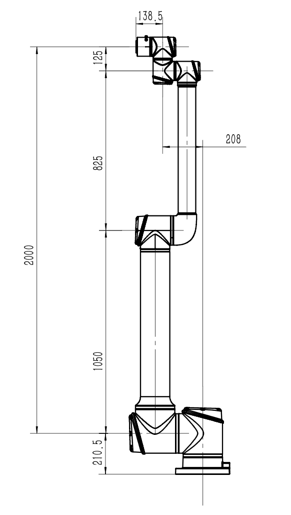
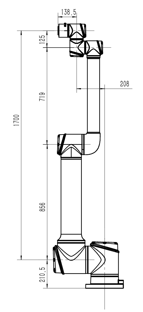
3.4.2 Moving Range of Body Point P
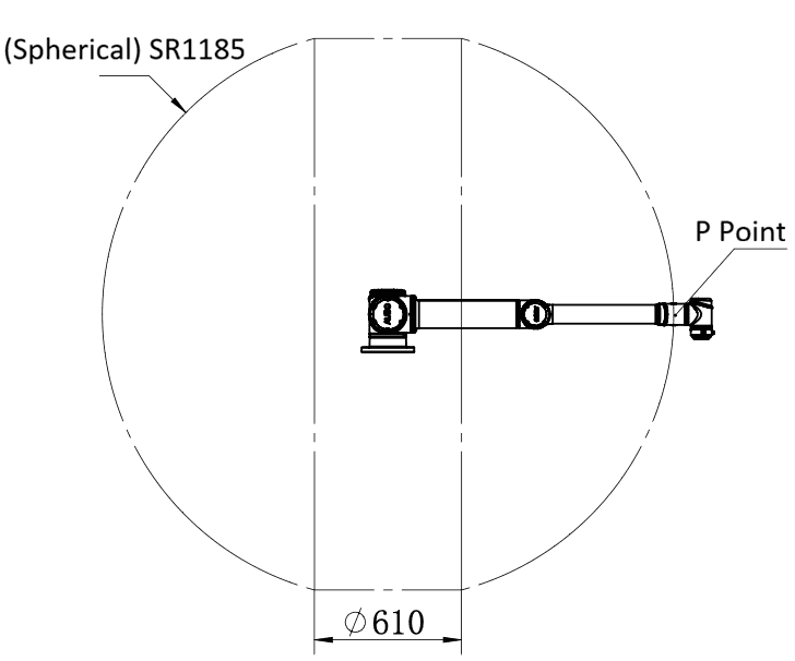
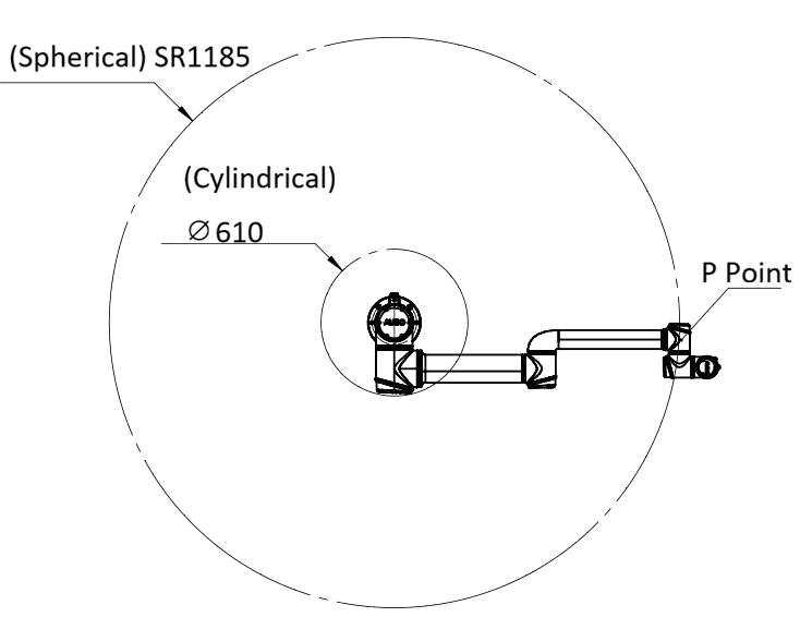
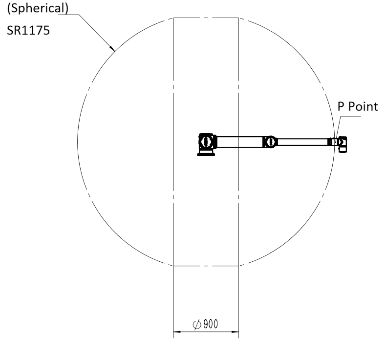
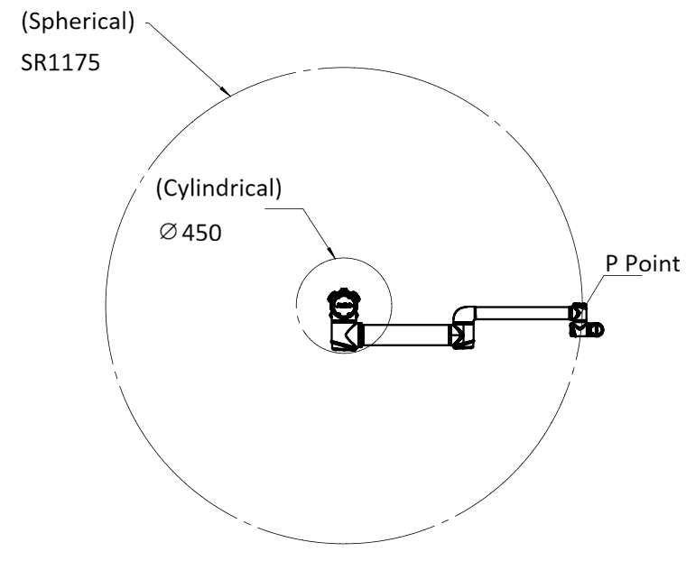
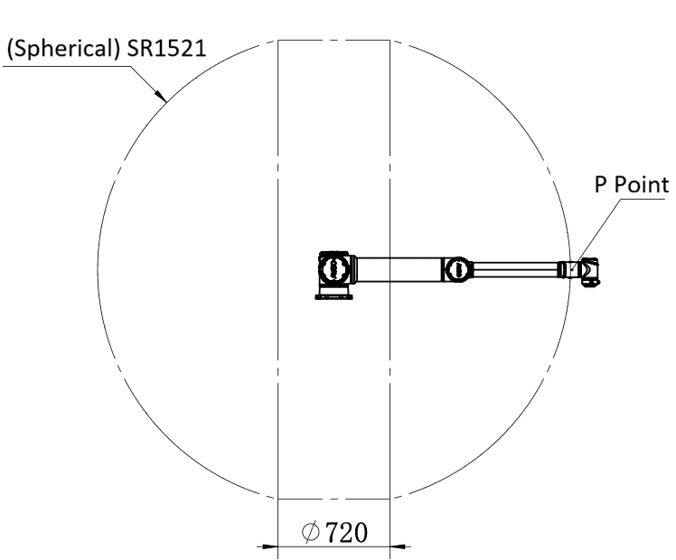
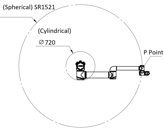
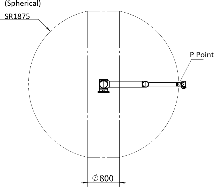
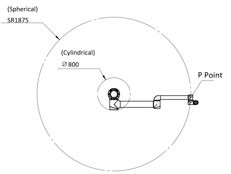
For each model, the following figures show the side view and top view of the motion range of body Point P.
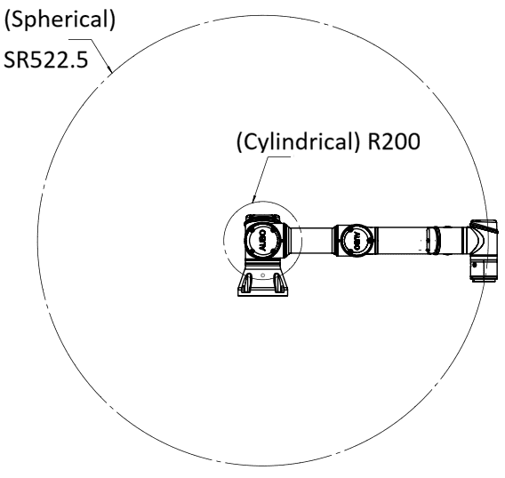
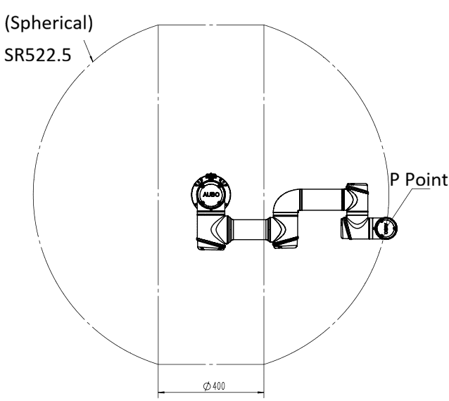
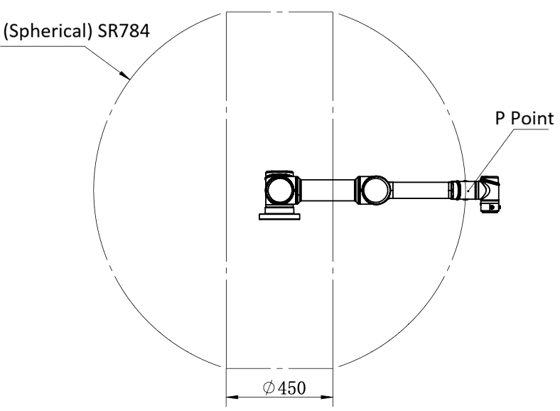
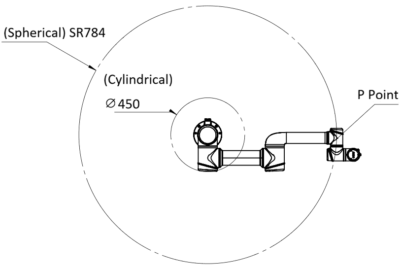
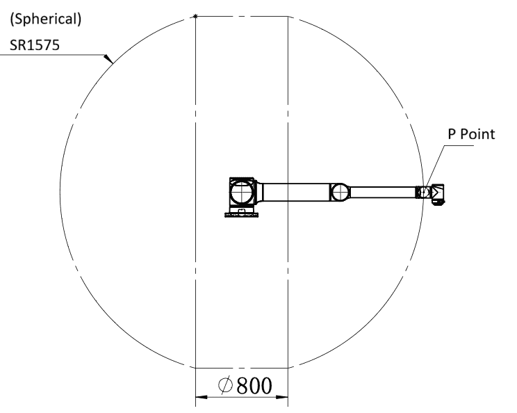
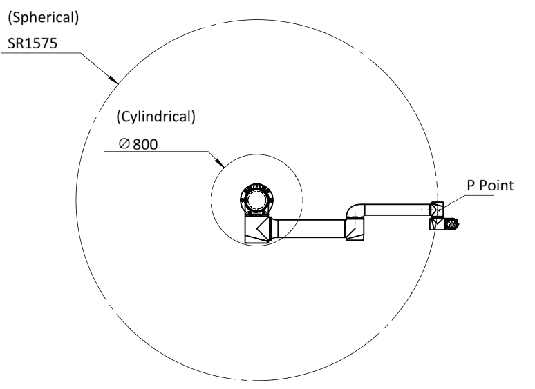
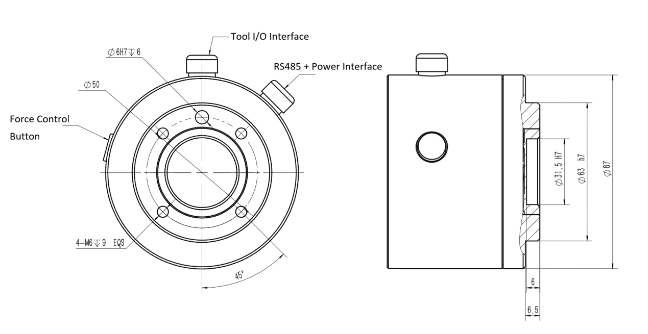
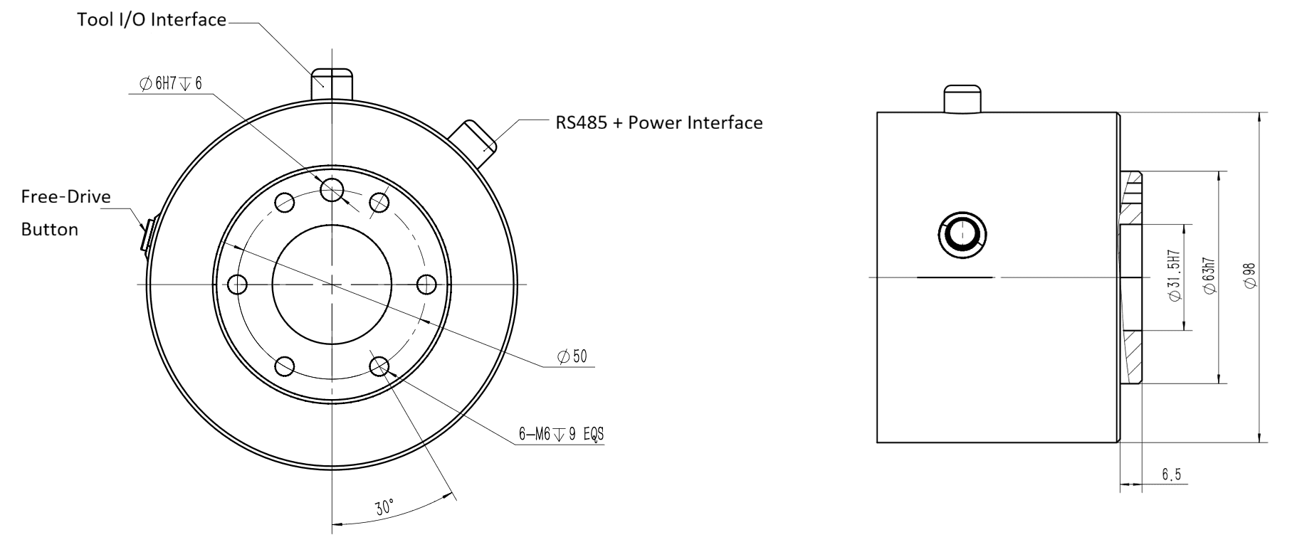
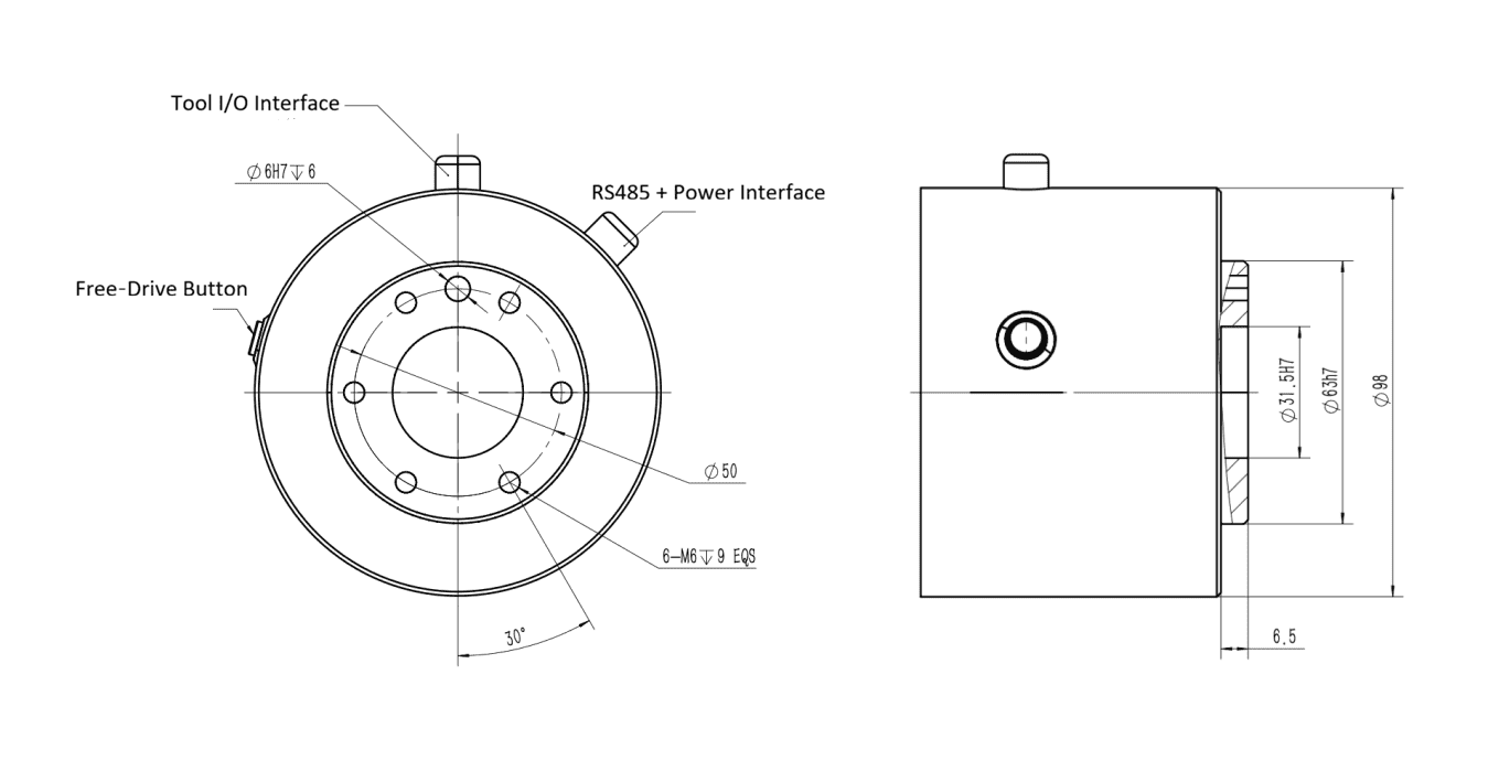
3.4.3 Mechanical Dimensions of Tool Flange
The end flanges used by different models of the iS Series Pro robot arm vary slightly. The end flange has several threaded holes and one locating hole.
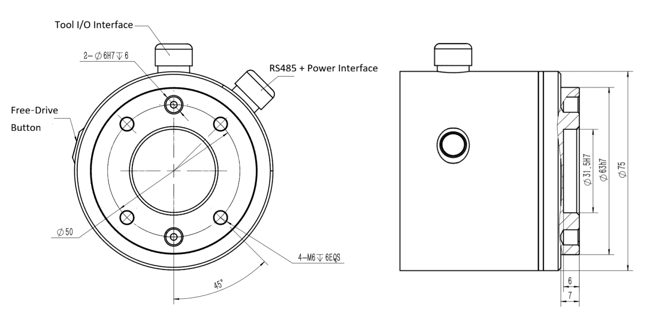
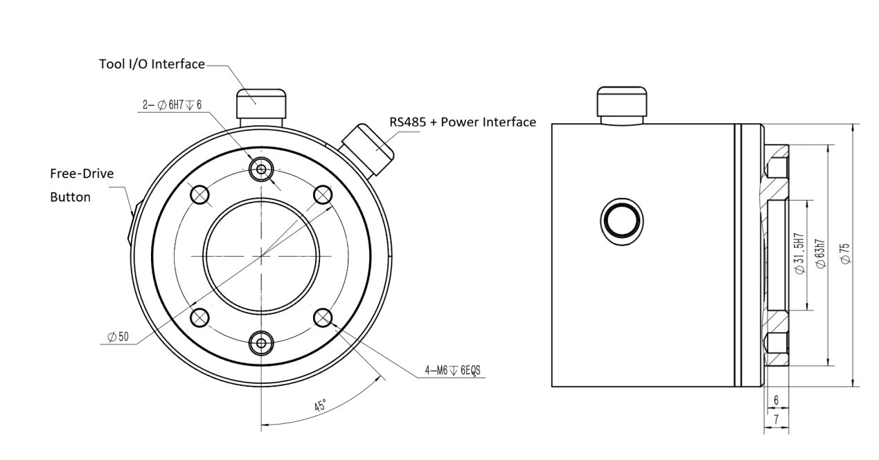
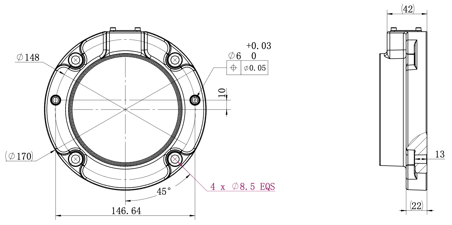
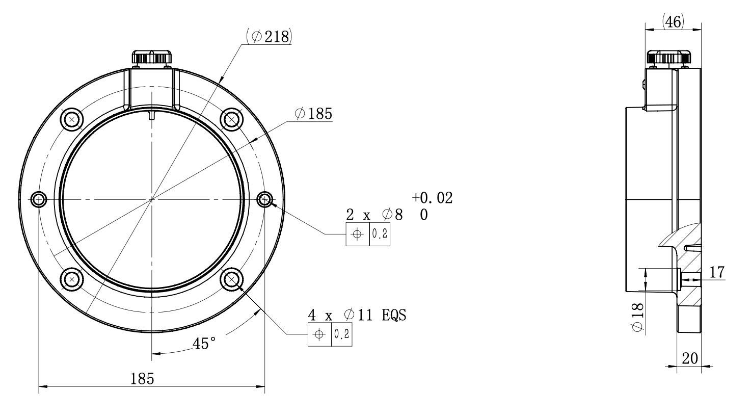
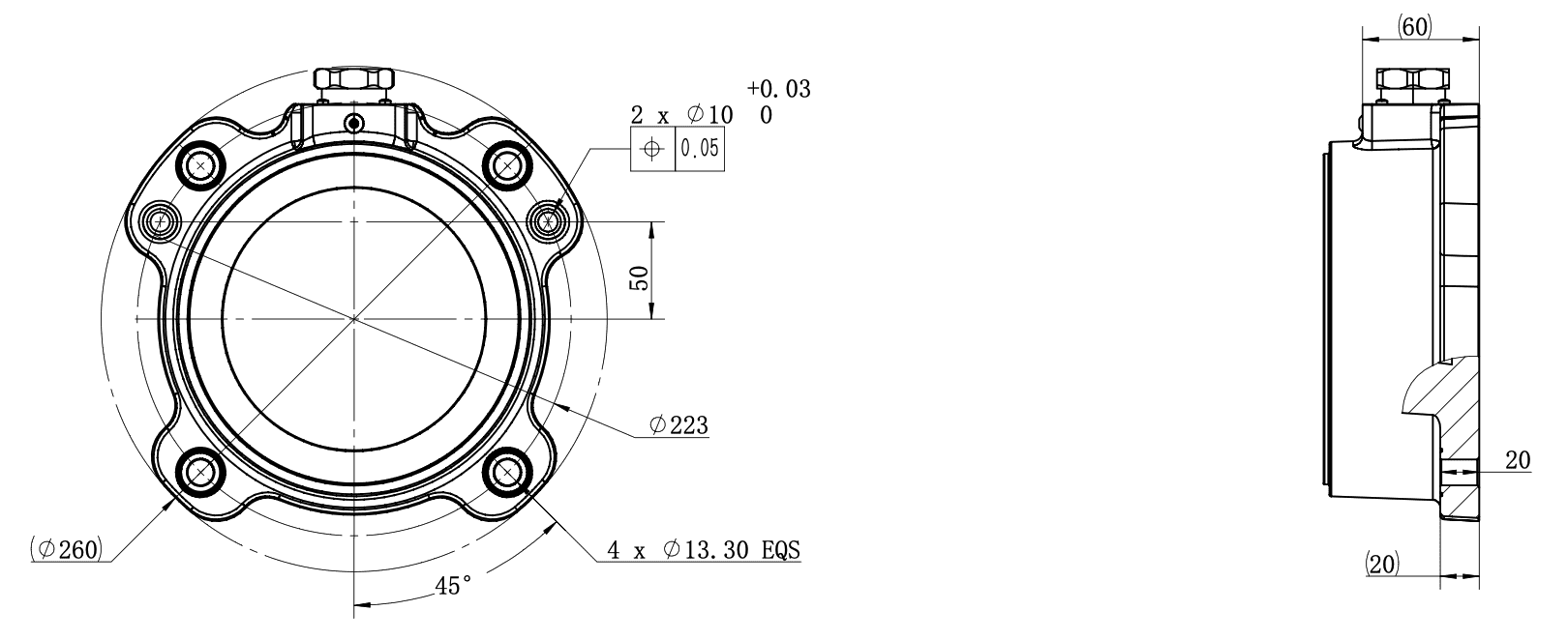
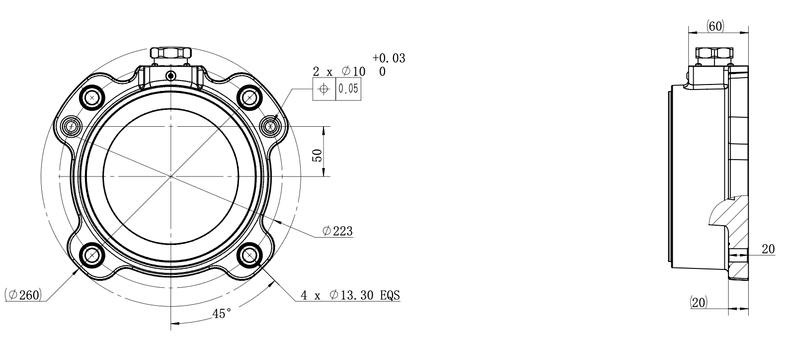
3.4.4 Top View of Base

4 Installation and Commissioning
4.1 Important Safety Instructions
4.1.1 Environmental Conditions
The robot arm shall be installed in an environment that meets the following conditions:
- No corrosive gas or liquid
- No oil mist
- No smoke
- No dust or metal powder
- No mechanical shock or vibration
- No electromagnetic noise
- No radioactive materials
- Low humidity
- No flammable materials
- Ambient temperature: 0°C ~ 50°C
- Avoid direct sunlight exposure and avoid outdoor use
4.1.2 Safety Requirements
The installation foundation shall meet the following mechanical load-bearing requirements:
- Load-bearing capacity: Install the robot on a solid surface capable of withstanding at least 10 times the full torsional force of the base joint and at least 5 times the weight of the robot arm.
- Stability: The mounting surface shall be free of vibration and shall not become loose after installation.
Instructions for installing additional devices:
If non-AUBO original supporting components, such as cables, are added to the robot, the user shall ensure that such components do not interfere with or impair equipment safety functions.
Controller safety instructions:
- The controller shall be placed horizontally on the floor.
- A clearance of ≥ 50 mm shall be reserved on each side of the controller to ensure ventilation and heat dissipation.
- The teaching pendant may be hung on the controller. Ensure that cables do not trip personnel.
| Symbol | Description |
|---|---|
| 1. A wet controller may cause injury or death. 2. Pay close attention to environments where conductive dust is present. |
4.2 Installation Precautions for High-Payload Robot Arms
For robot arms with a rated payload of 20 kg or above, uncontrolled motion may cause irreversible serious injury or even death. The following safety requirements must be strictly observed during installation.
4.2.1 Pre-Installation Preparation
- Before installation, complete a risk assessment of the robot arm installation scenario and identify potential hazards during hoisting, fixing, electrical connection, and other processes, such as mechanical crushing, falling objects, and electric shock.
- All personnel involved in installation must have received targeted training or provide verified evidence of safety competence in handling high-payload servo systems.
- For high-payload robots, it is recommended to provide means of limiting their motion space, such as mechanical stops, electromechanical devices, or certified safety software.
- It is recommended to install safety fences, safety light curtains, and other protective devices. Safety fence height shall be greater than 2000 mm, and the minimum shall not be less than 1400 mm. Ground clearance shall not exceed 180 mm. Protective panel fasteners must use captive bolts to ensure reliable replacement of protective panels after maintenance. The minimum safety distance S of a safety light curtain must be calculated using
, based on personnel approach speed (K), robot arm stopping time (T), and intrusion distance (C).
4.2.2 Handling and Hoisting Safety Requirements
- Robot arms with a rated payload of 20 kg or above must not be handled manually. Manual handling poses significant safety risks, including personal injury, falling objects, and equipment damage. Such robot arms must be handled and hoisted using compliant dedicated equipment, and the entire process must comply with safety requirements.
- During hoisting, the influence of the end effector on the center of gravity must be considered. Remove it first if necessary.
- Hoisting operations must be directed by a designated person. Unauthorized personnel are prohibited from entering the operation radius during hoisting. Hoisting personnel must have the corresponding safety competence qualifications.
4.2.3 Foundation Engineering Requirements
Robot arms with a rated payload of 20 kg or above have large dynamic inertia. The installation floor must undergo professional structural calculation. To meet the foundation stability requirements of ISO 10218-2:2025, the following technical standards are recommended:
- Material strength: The robot installation foundation should be reinforced concrete with a strength grade not lower than C30, corresponding to approximately 4000 psi under international standards, to ensure that anchor bolts do not loosen under the large overturning moment generated during emergency stop.
- Installation accuracy: Mounting surface flatness tolerance
, to prevent internal stress in the base casting during fastening.
Equipotential bonding: The robot arm body must be equipotentially bonded. Grounding resistance shall be ≤ 4Ω. Grounding terminals shall be firmly connected without looseness, and grounding cable specifications shall match the robot arm power requirements.
4.3 Installing the Robot Arm
Installation of the robot arm consists of the following main steps:
- Determine the workspace: Plan a safe working area according to the motion range of the robot arm.
- Install the robot arm body: Secure the robot arm to the base or workbench.
- Install the end effector: Mount the end effector to the robot arm flange.
- Connect the controller: Complete electrical connections according to the controller manual.
- Power-on commissioning: After power-on, complete initial configuration through the teaching software.
After every robot installation, a safety assessment must be carried out, and the requirements in the safety chapter of this manual must be strictly followed.
4.3.1 Base (Optional)
The AUBO robot base is an optional component used to support and fix the robot arm. Figure 4-1 shows a schematic diagram of the base structure. The actual equipment shall prevail.
AUBO provides two specifications of bases. Their appearance, applicable payloads, and structure descriptions are as follows:
| Base Type | Color | Applicable Payload | Structure Description |
|---|---|---|---|
| Low-payload base | Silver | Max. 5 kg payload | Equipped with 4 leveling bolts and 4 swivel casters for easy fixing and movement. To fix the robot arm, rotate the upper part of the leveling bolt to lower the leveling bolt. To move the robot arm, use a wrench to rotate the lower nut of the leveling bolt and raise the leveling bolt so that the swivel caster is released from the floor. |
| High-payload base | Black | Typically used for 7 kg and 10 kg payloads, up to a maximum of 20 kg | Equipped with 4 leveling bolts, specially designed for stable installation. To fix the robot arm, rotate the handwheel to adjust the leveling bolt height, and use an adjustable wrench to tighten the nut. |
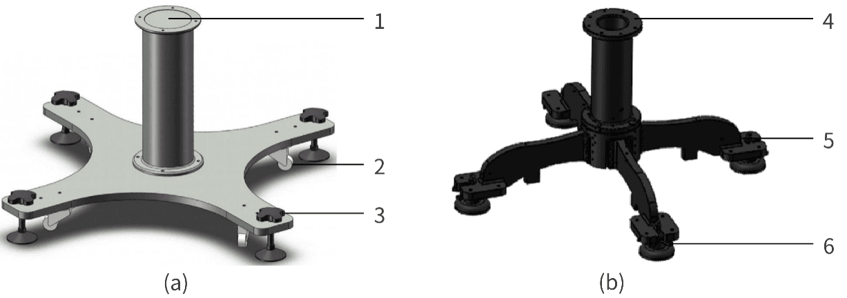
Observe the following requirements when selecting and using the base:
| Sign | Description |
|---|---|
| 1. Select a base that matches the payload capacity of the robot arm: the silver low-payload base supports a maximum payload of 5 kg; the black high-payload base is typically used for 7 kg and 10 kg payloads, up to a maximum of 20 kg. 2. The bottom of the base is not fixed to the floor. It is suitable only for simple commissioning scenarios and must not be operated at full payload and full speed; otherwise, there is a risk of tip-over. |
4.3.2 Installing the Robot Arm
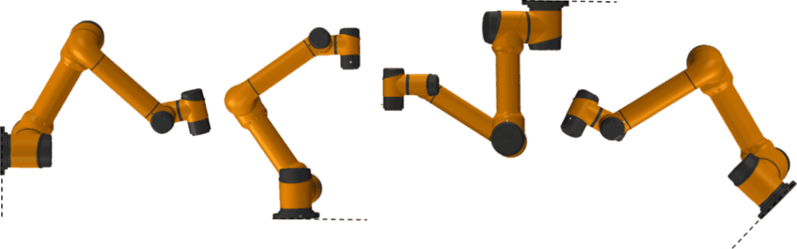
The iS Series Pro robot arm features 360° installation-position and pose self-adaptation, supporting base mounting, ceiling mounting, wall mounting, and other installation methods, as shown in Figure 4-2. After the robot arm is installed, the teaching software automatically detects and adjusts the operating parameters of the robot arm after power-on.
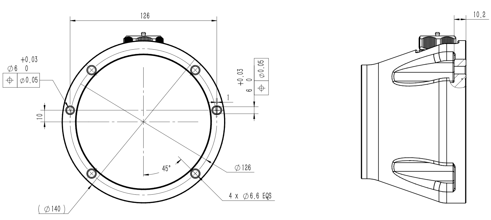
When installing on a base, it is recommended to use four bolts for fastening and to pre-install locating pins in two slightly smaller holes to improve installation accuracy. For mechanical dimensions, refer to Section 3.4.4 Top View of Base.
| Symbol | Description |
|---|---|
| 1. Ensure that the robot arm is correctly and securely installed. 2. The robot arm shall not be installed in water or humid environments unless it is declared to have an IP67 rating. Otherwise, if the robot arm remains immersed in water for a period of time, it may be damaged. 3. Tip-over hazard: If the robot arm is not securely placed on a solid surface, it may tip over and cause injury. |
| 1. When installed on a base, the contact surfaces of the robot and base must be in close contact. 2. It is recommended that users use a base contact surface with strong heat dissipation performance, such as all-aluminum material. When the working environment exceeds 35°C, materials with strong heat dissipation performance are strongly recommended. |
4.3.3 Installing the End Effector
The end effector flange has several threaded holes and one locating hole, allowing tools such as grippers to be conveniently mounted to the end of the robot arm. For mechanical dimensions of the tool flange, refer to Section 3.4.3 Mechanical Dimensions of Tool Flange.
| Symbol | Description |
|---|---|
| 1. Ensure that the tool is correctly and securely installed. 2. Ensure that the tool safety architecture prevents any risk of parts falling accidentally. |
4.3.4 Protective Grounding
The power input terminal of the robot arm controller must be connected to a qualified protective earth conductor (PE conductor) to ensure a good electrical connection between the enclosure and earth. It is strictly prohibited to power on the robot arm without connecting the protective earth conductor (PE conductor).
- Grounding technical requirements:
- Cable specification: The protective earth conductor (PE) must be a copper-core cable with a cross-sectional area ≥ 2.5 mm². The insulation layer must be intact, and terminals must be securely crimped using professional crimping tools. Twisted or wrapped connections are strictly prohibited.
- Grounding resistance: After grounding construction is complete, a grounding resistance tester must be used to measure the resistance between the robot arm PE terminal and earth. A grounding resistance ≤ 4Ω is qualified.
- Record keeping: Grounding test records must be retained on file as important evidence of safety compliance.
- Safety inspection and maintenance:
- Routine inspection: Operators shall regularly check the PE conductor connection status to ensure there is no looseness, breakage, or corrosion.
- Maintenance requirement: After equipment maintenance, relocation, or reinstallation, grounding resistance must be retested to ensure the continuous effectiveness of the grounding system.
- Training requirement: All operators must receive grounding safety training to understand the risks of ungrounded operation and the correct grounding method.
| Symbol | Description |
|---|---|
| 1. It is strictly prohibited to power on the robot arm without connecting the protective earth conductor (PE conductor). Missing or poor grounding may cause electric shock, abnormal electromagnetic interference, or permanent equipment damage. 2. When the robot arm is not connected to the PE conductor, the enclosure may carry an induced voltage of 15 V to 105 V. Contact may cause numbness, tingling, or other discomfort, which may trigger panic-related misoperation and lead to secondary hazards such as collision with the robot arm or accidental emergency stop activation. |
4.3.5 Cable Connection
After the robot arm is installed, the controller must be correctly connected before the robot can be powered on for normal use. For cable connection methods, refer to the controller user manual.
4.4 Arm-Side Interfaces and Buttons
4.4.1 Introduction
To meet the diverse requirements of end effectors, the iS Series Pro robot arm is designed with an 8-pin connector (hereinafter referred to as the "tool I/O interface"), a 4-pin connector (hereinafter referred to as the "tool RS485 interface"), and a hand-guiding button at the wrist. The tool RS485 interface is optional.
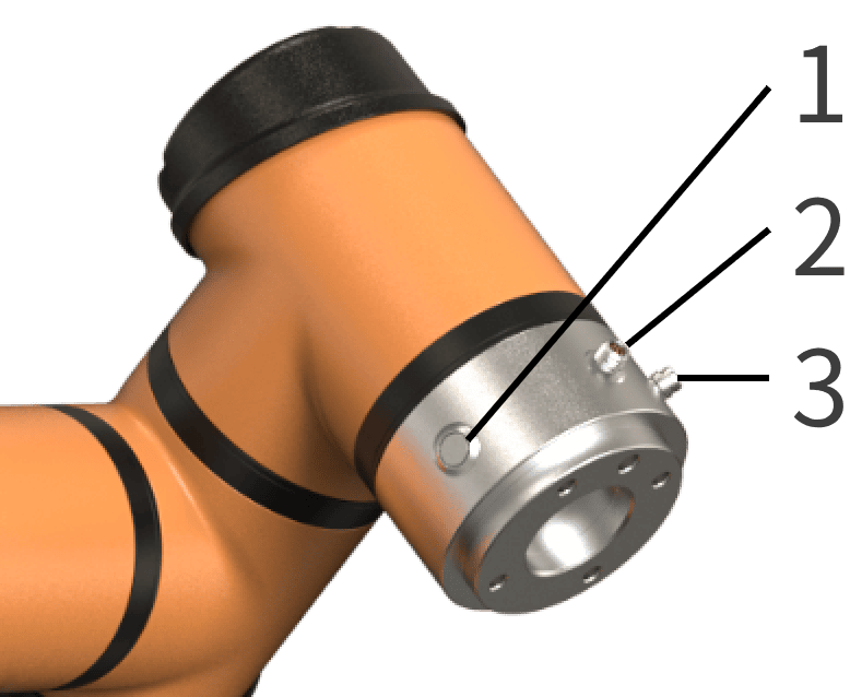
4.4.2 Tool I/O Interface
The tool I/O interface integrates power supply and signal transmission functions, supporting connection and control of end effector devices such as grippers and sensors. It uses an industrial-grade cable connection and contains eight function wires internally, as shown in Figure 4-4 and Table 4-1. Power voltage, digital I/O interface mode, I/O interface functions, and other parameters can be configured in the teaching software. For configuration methods and functions, refer to the AuboStudio User Manual.
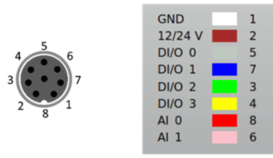
| Color | Signal | Pin | Color | Signal | Pin |
|---|---|---|---|---|---|
| White | GND | 1 | Green | DI/O 2 | 3 |
| Brown | 12/24 V | 2 | Yellow | DI/O 3 | 4 |
| Gray | DI/O 0 | 5 | Red | AI 0 | 8 |
| Blue | DI/O 1 | 7 | Pink | AI 1 | 6 |
The digital I/O interface of the tool I/O interface adopts an NPN switching scheme:
- Digital input mode: when activated, the connector is driven to GND; when disabled, it is in an open-circuit state.
- Digital output mode: a weak pull-down resistor is provided to ensure signal stability and reliability.
For detailed electrical parameters of the tool I/O interface, see Table 4-2 to Table 4-4. Electrical tolerance is within ±10%.
| Parameter | Minimum | Typical | Maximum | Unit |
|---|---|---|---|---|
| Power supply voltage in 24 V mode | 23 | 24 | 25 | V |
| Power supply voltage in 12 V mode | 11.5 | 12 | 12.5 | V |
| Power supply current in both modes | - | 0.35 | 1.0 | A |
| Parameter | Minimum | Typical | Maximum | Unit |
|---|---|---|---|---|
| Input voltage range | 0 | - | 10 | V |
| Voltage resolution | - | 2.5 | - | mV |
| I/O type | Parameter | Minimum | Typical | Maximum | Unit |
|---|---|---|---|---|---|
| Digital input interface | Input voltage | -0.5 | - | Vout+2 | V |
| Logic low voltage | 0 | 1.5 | 2 | V | |
| Logic high voltage | Vout-4 | Vout | Vout+2 | V | |
| Input resistance | - | 4.3 | - | kΩ | |
| Digital output interface | Open-circuit voltage | Same as supply voltage | |||
| Voltage at 1 A input current | 0.35 | 0.4 | 0.85 | A | |
| Input current | 0.35 | 0.4 | 0.5 | A | |
| Current through GND | 0.35 | 0.4 | 0.5 | A | |
| Analog input interface | AI0 | 0 | - | +10 | V |
| AI1 | 0 | - | +10 | V | |
| Symbol | Description |
|---|---|
| When connecting tools and grippers, ensure that interruption of power supply does not create any hazard, such as a workpiece falling from the tool. |
4.4.3 Tool RS485 Interface
The tool RS485 interface provides fieldbus communication capability and supports direct communication and data exchange with multiple devices. It adopts the standard RS485 communication protocol, uses an industrial cable connection, and contains four function wires internally, as shown in Figure 4-5 and Table 4-5. Its power supply voltage is configured in the same way as the tool I/O interface. For configuration methods and functions, refer to the AuboStudio User Manual. For related electrical parameters, see Table 4-2.

| Color | Signal | Pin |
|---|---|---|
| Brown | 12/24 V | 1 |
| White | RS485A | 2 |
| Blue | RS485B | 3 |
| Black | GND | 4 |
4.4.4 Hand-Guiding Button
The hand-guiding button is a human-machine interface component provided by the iS Series Pro robot arm. Press and hold the button to enter hand-guiding mode, in which the user can easily move the robot arm. After the button is released, the robot arm maintains the current pose and exits hand-guiding mode. This function can be used together with the "trajectory recording" function. For details, refer to the AuboStudio User Manual.
5 Handling and Transportation Precautions
When hoisting the robot, appropriate measures shall be taken to secure moving parts and prevent unexpected movement during hoisting and transportation, which could create hazards. During packaging for transportation, pack the robot according to packaging standards and mark the outside of the packaging box as required.
During transportation, ensure that the robot is stable and fixed in an appropriate position.
The controller shall be lifted using the handle.
When moving the robot from its packaging materials to the installation position, support the robot until all robot base bolts are fully tightened.
After securing the robot, power it on and use the hand-guiding function to adjust the robot pose to an appropriate position.
After transportation, keep the original packaging in good condition. Store the packaging materials in a dry place for future repackaging and relocation of the robot.
| Symbol | Description |
|---|---|
| 1. Ensure that your back or other body parts are not overloaded when lifting equipment. 2. All regional and national guidelines shall be followed. AUBO (Beijing) Intelligent Technology Co., Ltd. is not responsible for damage occurring during equipment transportation. 3. Ensure that robot installation strictly follows the installation instructions in this manual. |
6 Maintenance, Repair, and Disposal
6.1 Maintenance and Repair
All maintenance and repair operations must strictly comply with all safety requirements in this manual.
Equipment maintenance, calibration, and repair shall be carried out according to the latest service manual, which is available from the official technical support website www.aubo-robotics.com. All authorized distributors of AUBO (Beijing) Intelligent Technology Co., Ltd. may access this website.
Equipment repair may only be performed by authorized system integrators or AUBO personnel. If components must be returned to AUBO (Beijing) Intelligent Technology Co., Ltd., the relevant procedures in the service manual must be strictly followed.
During work, the safety level required for the corresponding maintenance or repair operation shall be met, and applicable local production safety regulations shall be observed. After completion, all safety functions must be tested one by one to confirm normal operation.
Maintenance and repair work is intended to ensure stable equipment operation or restore normal conditions after failure. It includes both fault diagnosis and physical repair.
When operating the robot arm body or controller, strictly follow the following safety procedures and warnings:
| Symbol | Description |
|---|---|
| 1. Remove the main input cable from the back of the controller to ensure complete power disconnection. Necessary precautions shall be taken to prevent others from reconnecting system power during maintenance. After power is disconnected, recheck the system to confirm that it is powered off. 2. Check the grounding connection before restarting the system. 3. Observe ESD (electrostatic discharge) regulations when disassembling the robot arm or controller. 4. Avoid disassembling the power supply system of the controller. After the controller is switched off, its power supply system may retain high voltage for several hours. 5. Prevent water or dust from entering the robot arm or controller. |
| 1. Replace faulty parts with new parts of the same part number or corresponding parts approved by AUBO (Beijing) Intelligent Technology Co., Ltd. 2. Immediately reactivate all disabled safety measures after the work is completed. 3. Record all repair operations in writing and retain them in the technical documentation related to the complete robot system. 4. The controller contains no parts serviceable by the end user. If maintenance or repair services are required, contact your distributor or AUBO (Beijing) Intelligent Technology Co., Ltd. |
6.2 Disposal
AUBO robots must be disposed of in accordance with applicable national laws, regulations, and national standards.
7 Quality Assurance
7.1 Product Warranty
The iS Series Pro robot arm body is covered by a 36-month limited warranty. The built-in six-axis force sensor at the end of the robot arm is covered by a 12-month limited warranty.
If new equipment or its components show defects caused by poor manufacturing or materials within 36 months after being put into use, AUBO (Beijing) Intelligent Technology Co., Ltd. shall provide necessary spare parts to replace or repair the relevant components.
Ownership of replaced equipment or components, or equipment or components returned to AUBO (Beijing) Intelligent Technology Co., Ltd., belongs to AUBO (Beijing) Intelligent Technology Co., Ltd.
If the product is outside the warranty period, AUBO (Beijing) Intelligent Technology Co., Ltd. reserves the right to charge the customer for replacement or repair.
Outside the warranty period, if the equipment exhibits defects, AUBO (Beijing) Intelligent Technology Co., Ltd. shall not be liable for any resulting damage or loss, such as production loss or damage to other production equipment.
7.2 Disclaimer
If equipment defects are caused by improper handling or failure to follow the relevant information described in the user manual, the product warranty becomes invalid.
Failures caused by the following conditions are not covered by this warranty:
- Products purchased through channels not approved by AUBO.
- Installation, wiring, or connection to other control equipment that does not comply with industrial standards or the requirements of the user manual.
- Use beyond the specified conditions or standards of the product.
- Use of the product for purposes other than those specified.
- Environmental conditions exceeding product specifications.
- Use in grinding environments or special operating environments without product protection.
- Product damage caused by improper transportation.
- Failures, damage, or consequential damage caused by accidents or human factors.
- Failures, damage, or consequential damage caused by modification.
- Installation of non-original genuine parts or accessories.
- Damage caused by modification, commissioning, or repair of original parts by a third party other than AUBO (Beijing) Intelligent Technology Co., Ltd. or its designated integrator.
- Failures, damage, or consequential damage caused by natural disasters or other force majeure events.
- Failures caused by reasons other than the responsibility of AUBO (Beijing) Intelligent Technology Co., Ltd., in addition to the above.
The following circumstances are not covered by the warranty:
- The product traceability number cannot be identified.
- The production date or warranty start date cannot be identified.
- Changes to software or internal data.
- The fault cannot be reproduced or cannot be identified by AUBO (Beijing) Intelligent Technology Co., Ltd.
- Use of this product in radioactive equipment, biological testing equipment, or applications deemed hazardous by AUBO (Beijing) Intelligent Technology Co., Ltd.
- Appearance parts and wearing parts. According to the product warranty agreement, AUBO (Beijing) Intelligent Technology Co., Ltd. only provides warranty commitments for defects and deficiencies in products and parts sold to distributors.
AUBO (Beijing) Intelligent Technology Co., Ltd. disclaims any other express or implied warranties or liabilities, including but not limited to any implied warranty of merchantability or fitness for a particular purpose. In addition, AUBO (Beijing) Intelligent Technology Co., Ltd. shall not be liable for any indirect or consequential damage of any kind arising from related products.
8 Appendix
8.1 Terms
Category 0 stop: Uncontrolled stop, power is cut off immediately and the joint brakes apply with no controlled deceleration, so the robot may deviate from the programmed path. It applies only to extreme cases such as exceeding the safety-rated limit or a failure in the safety-rated part of the control system. For the definitions of stop categories and the requirement to remove power immediately, refer to IEC 60204-1:2016 (9.2.2 Stop categories); for the design requirements of the emergency stop function, refer to EN ISO 13850:2015.
Category 1 stop: Controlled stop with power removal afterwards, the robot stops along the programmed path and the power is removed once the stop is achieved, balancing safety and path stability. For the definitions of stop categories and the requirement to remove power after the stop, refer to IEC 60204-1:2016 (9.2.2 Stop categories); for the design requirements of the emergency stop function, refer to EN ISO 13850:2015.
Category 2 stop: Controlled stop with power maintained, the robot stays powered after it stops, and the safety-rated control system holds it in the stopped position, so work can be resumed quickly. For the definitions of stop categories and the requirement to maintain power, refer to IEC 60204-1:2016 (9.2.2 Stop categories). A category 2 stop is not permitted as an emergency stop, and is therefore not covered by EN ISO 13850:2015.
Integrator: The integrator is the organization that designs the final robot installation. The integrator is responsible for final risk assessment and must ensure that the final installation complies with local laws and regulations.
Risk assessment: Risk assessment is the complete process of identifying all risks and reducing them to an appropriate level. Risk assessment shall be documented and archived. For details, refer to ISO 12100.
Performance level: Performance Level (PL) is a discrete level used to describe the ability of safety-related parts of a control system to perform a safety function under foreseeable conditions. PLd is the second-highest reliability classification, indicating that the safety function is highly reliable. For more information, refer to EN ISO 13849-1:2008.
8.2 Revision Records
| Version | Date | Revision Description |
|---|---|---|
| v1.0.0* | 2026-08-10 | 1. Released v1.0.0* trial version. |
| v1.0.1* | 2026-08-27 | 1. Released v1.0.1* trial version. 2. Unified manual structure, safety instructions, chapter names, and warning signs. |
| v1.0.2* | 2026-09-22 | 1. Released v1.0.2* trial version. 2. Added the stop category description for the emergency stop button and unified the glossary wording in the appendix. |
| v1.0.3* | 2026-10-13 | 1. Released v1.0.3* trial version. 2. Updated the foundation engineering requirements for heavy-payload robot arms. |
8.3 Technical Specifications Summary
| Parameter | iS3 Pro | iS7 Pro | iS10 Pro | iS16 Pro | iS20 Pro | iS20L Pro | iS25 Pro |
|---|---|---|---|---|---|---|---|
| Degrees of freedom | 6 rotary joints | 6 rotary joints | 6 rotary joints | 6 rotary joints | 6 rotary joints | 6 rotary joints | 6 rotary joints |
| Weight | 16 kg | 21.5 kg | 36 kg | 64 kg | 64 kg | 72 kg | 75.6 kg |
| Payload | 3 kg | 7 kg | 12 kg | 16 kg | 20 kg | 20 kg | 25 kg |
| Maximum working radius | 625 mm | 886.5 mm | 1300 mm | 1900 mm | 1647 mm | 2000 mm | 1700 mm |
| Joint range | joint1/joint2/joint4/joint5/joint6: ±360° joint3: ±156° | joint1/joint2/joint4/joint5/joint6: ±360° joint3: ±162° | joint1/joint2/joint4/joint5/joint6: ±360° joint3: ±165° | joint1/joint2/joint4/joint5/joint6: ±360° joint3: ±165° | joint1/joint2/joint4/joint5/joint6: ±360° joint3: ±165° | joint1/joint2/joint4/joint5/joint6: ±360° joint3: ±165° | joint1/joint2/joint4/joint5/joint6: ±360° joint3: ±165° |
| Maximum joint speed | joint1/joint2/joint3/joint4/joint5/joint6: 237°/s | joint1/joint2/joint3: 237°/s joint4/joint5/joint6: 300°/s | joint1/joint2: 280°/s joint3: 237°/s joint4/joint5/joint6: 300°/s | joint1/joint2: 190°/s joint3: 280°/s joint4/joint5/joint6: 300°/s | joint1/joint2: 190°/s joint3: 280°/s joint4/joint5/joint6: 300°/s | joint1/joint2: 140°/s joint3: 280°/s joint4/joint5/joint6: 300°/s | joint1/joint2: 140°/s joint3: 280°/s joint4/joint5/joint6: 300°/s |
| Tool speed | ≤ 2.5 m/s | ≤4.3 m/s | ≤6.3 m/s | ≤6.3 m/s | ≤5.4 m/s | ≤4.8 m/s | ≤4.1 m/s |
| Repeatability | ±0.02 mm | ±0.02 mm | ±0.03 mm | ±0.05 mm | ±0.05 mm | ±0.05 mm | ±0.05 mm |
| Operating ambient temperature range | 0-50°C | 0-50°C | 0-50°C | 0-50°C | 0-50°C | 0-50°C | 0-50°C |
| Operating ambient humidity | 90% RH (non-condensing) | 90% RH (non-condensing) | 90% RH (non-condensing) | 90% RH (non-condensing) | 90% RH (non-condensing) | 90% RH (non-condensing) | 90% RH (non-condensing) |
| IP rating | IP66 | IP66 | IP66 | IP66 | IP66 | IP66 | IP66 |
| Average power | Approx. 150 W when running typical programs | Approx. 200 W when running typical programs | Approx. 500 W when running typical programs | Approx. 1000 W when running typical programs | Approx. 1000 W when running typical programs | Approx. 1000 W when running typical programs | Approx. 1000 W when running typical programs |
| Peak power | 1000 W | 2000 W | 2000 W | 3000 W | 3000 W | 3000 W | 3000 W |
| Mounting surface diameter | ø140 mm | ø170 mm | ø218 mm | ø260 mm | ø260 mm | ø282 mm | ø282 mm |