I/O Tab
AuboStudio can monitor and set the status of all controllers, body ends, and I/O ports of external devices. In the [I/O] tab, you can monitor the status of each I/O port and can also operate the signal of the output port.
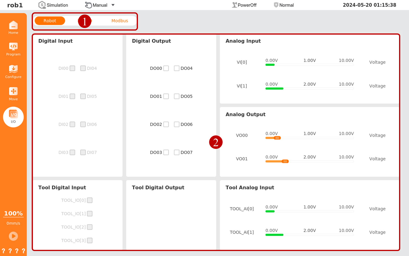
This system is classified according to the nature of I/O ports: Under the [Robot] tab, there are all user-operable I/Os, such as digital I/O, analog I/O, and tool I/O; under the [Link IO] tab, there are safety I/O and system internal I/O; under the [Modbus] tab, there are I/Os of external devices.
- General I/O: I/O with user custom function.
- Configurable I/O: It can be used as general I/O or as safety I/O. When configured for a single I/O function, it can be used as a general I/O. When configured for a configurable I/O, it can be used as safety I/O.
- Linked I/O: I/O with fixed functions, such as remote power on/off on the controller.
- Tool I/O: Specifically refers to the I/O at the end of the tool.
Info
The update frequency of the [I/O] tab is 20 Hz, so signals with frequencies above 20 Hz may not be displayed correctly.
| Serial number | Name | Description |
|---|---|---|
| 1 | I/O tab | Select I/O category |
| 2 | I/O list | Display I/O under the current category |
Introduction to I/O signal status
Only some models of controllers support NPN/PNP mode switching. Please refer to the Hardware User Manual for details.
| Name | English | Description |
| Logic High | Logic High | High-level state in a digital signal. * In NPN mode, when the digital I/O port is in logic high, the output will be in the "on" state and the voltage will be close to the ground voltage (such as 0 V). * In PNP mode, when the digital I/O port is in logic high, the output will be in the "on" state and the voltage will be close to the power supply voltage (such as 24 V). |
| Logic Low | Logic Low | Low-level state in a digital signal. * In NPN mode, when the digital I/O port is in logic low, the output will be in the "off" state, and the voltage will have no output and will be cut off. * In PNP mode, when the digital I/O port is in logic low, the output will be in the "off" state, and the voltage will have no output and will be cut off. |
| Rising edge | Rising Edge | Transition edge of a signal from logic low to logic high. |
| Falling edge | Falling Edge | Transition edge of a signal from logic high to logic low. |
| Maximum voltage | Maximum Voltage | The maximum voltage is the highest voltage value that can be achieved by an analog signal. For the specific range of analog signal, please refer to the Hardware User Manual. |
| Minimum voltage | Minimum Voltage | The minimum voltage is the lowest voltage value that can be achieved by an analog signal. For the specific range of analog signal, please refer to the Hardware User Manual. |