Programming Interface Description
The robot program can be created or written through page [Program].
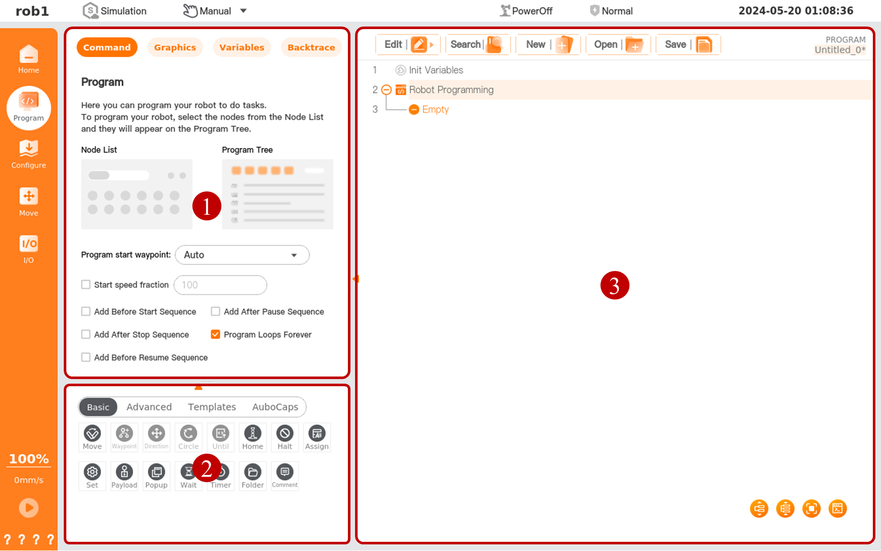
| Serial number | Name | Description |
|---|---|---|
| 1 | Program Information Card | Include Configure tabs: Command, Graph, Variable, and Track. |
| 2 | Program Node Card | Containing node classification and node list. |
| 3 | Programming Card | Containing the program manager toolbar, program tree, and program tree toolbar. |
Program information card
Command
The [Command] page is for you to configure nodes selected in the program tree. After a program node is selected, the configurable items of the node will be displayed/can be set on the page [Command].
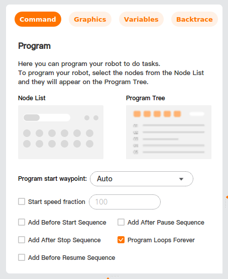
Program start waypoint: set the waypoint from which the program starts running.
- Auto: Click [Run] to enter the [Move] interface, move the robot arm to the start waypoint, and then click [OK] to start running the program.
- Ignore: Click [Run]. Then, the robot arm moves to the start waypoint, and the program starts running.
Start speed fraction: Check to set the start speed fraction of the program.
Add Before Start Sequence: Check to add a sequence to be executed before the master program starts running.
Add After Pause Sequence: Check to add a sequence to be executed after the master program pauses.
Add Before Resume Sequence: Check to add a sequence to be executed before the master program resumes running.
Add After Stop Sequence: Check to add a sequence to be executed after the master program stops.
Program Loops Forever: Check to enable the master program to run continuously.
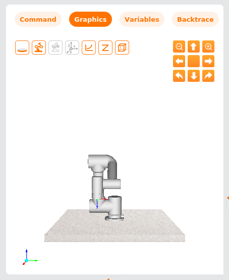
Graphics
The page [Graphic] displays the 3D model of the current robot, whose actions are consistent with those of the real robot.
| Icon | Name | Description |
|---|---|---|
| Up | Move the robot upward. | |
| Down | Move the robot downward. | |
| Left | Move the robot left. | |
| Right | Move the robot right. | |
| Turn left | Turn the robot clockwise. | |
| Turn right | Turn the robot counterclockwise. | |
| Enlarge | Enlarge the robot. | |
| Micrify | Micrify the robot. | |
| Reset | Reset the robot's position and view. |
| Icon | Name | Description |
|---|---|---|
| Base | Hide/show base | |
| Robot arm | Hide/show robot arm | |
| Target position/pose | Hide/show position/pose of target waypoint | |
| User coordinate system | Hide/show user coordinate system | |
| Track | Hide/show track | |
| Waypoint | Hide/show waypoint | |
| Obstacle | Hide/show obstacles | |
| Tool envelope ball | Hide/show tool envelope ball | |
| Point cloud | Hide/show point cloud |
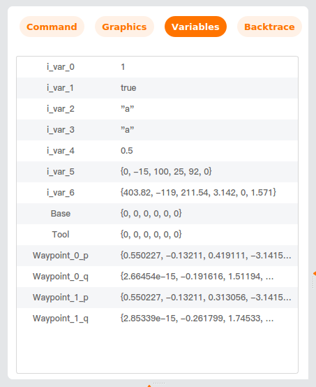
Variables
The page [Variables] displays the base coordinate system, tool coordinate system, waypoint joint angle, and end-of-tool TCP position/pose of the running program, as well as all the variables and values in the programs and profiles. The information shown in this page is the same as that on the page called out by "Home > Variables."
For information on variable types and data types, please refer to "Configuration - General - Variables."
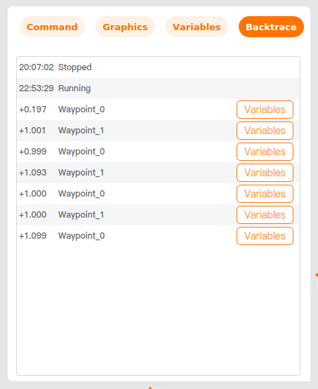
Tracking
The page [Backtrace] displays the start waypoint of the current program and the time when the program runs the node. You can click [Variables] in the log list to view the detailed information, offering convenience for your program debugging.
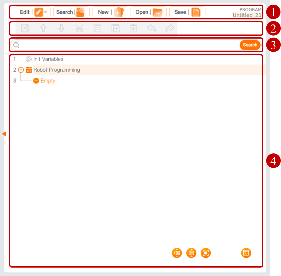
Programming card
The programming card displays or allows the user to edit the program tree, manage the program files, etc.
| Serial number | Name | Description |
|---|---|---|
| 1 | Program manager tool bar | Manage program files. |
| 2 | Program tree toolbar | Edit the node in the program tree. |
| 3 | Search box | Enter keyword to search for nodes in the program tree. |
| 4 | Program tree | Display or edit programs. |
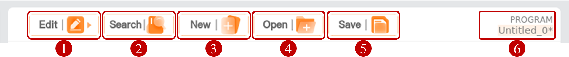
Program manager tool bar
| Serial number | Name | Description |
|---|---|---|
| 1 | Edit | Show/hide the program tree toolbar. |
| 2 | Search | Show/hide the search box, in which a keyword can be entered to search for nodes in the program tree. |
| 3 | New | Create a new program file. |
| 4 | Open | Open the program file. |
| 5 | Save | Save the program file. |
| 6 | Program name | Display the name of the current program file. Click the program name to view the name of the profile associated with the current program file. |
Tip
- If you use the I/O interface or the Start/Stop button on the control handle to control the start/stop of the program, please save the program file first. Otherwise, the program cannot be started. For detailed I/O function settings, please refer to I/O Configuration. For the operation of the control handle, please refer to the Hardware User Manual.
- After a program is written, if the associated configuration file is modified, it is required to save the configuration file first and then the program file. Otherwise, a program runtime error may occur.
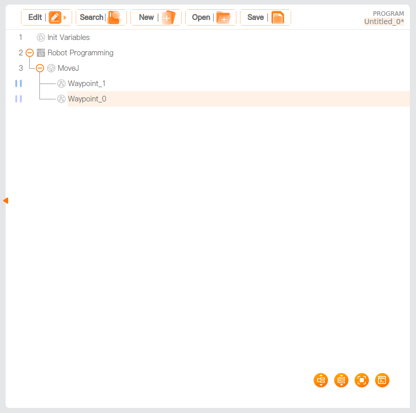
Program tree
Graphically programmed commands are added to the program tree, which can be called "program nodes" or " nodes" for short. Some nodes may contain other nodes, for example, the [Move] node, which can contain the [Waypoint] node. Such nodes can be called "program blocks". In other words, a program block is composed of multiple program nodes.
- Folding/unfolding a program block
- Click
 or
or .png) before the program block to expand it or make it collapse. -Double-click the program block name to unfold/fold this program block. (Recommended)
before the program block to expand it or make it collapse. -Double-click the program block name to unfold/fold this program block. (Recommended) - Click
 or
or  to expand all program blocks in the program tree or make them collapse.
- Click
- Folding/unfolding a program block
Initial variables: the first value assigned to the program variables when the program is started. The [Init Variables] node is added by default before the master program. In the [Init Variables] command page [Init Variables] for short), click the [Variables] dropdown box, select initial variables, and click the expression input box to assign the initial variables a value.
- Last-Run Value: when this is checked, the value of the initial variables is replaced with the value of the initial variables when the program is stopped. If a new program is loaded after the current program pauses, the value of the initial variables when the current program was stopped cannot be used and will be reset to the user setting.
Tip
To use this function normally, you are required to create a variable first. If you do not set the initial variables, the master program runs directly.
When the node in the program tree does not conform to the preset logic, the system will highlight associated nodes in yellow. When the node is configured in accordance with the preset logic, the system displays the node in black normally.
Breakpoint: To add a breakpoint to a line in the program tree, click the Line No. The newly set breakpoint is displayed in a darker color. After running to this line, the program will pause directly. At this time, click [Step] in the menu bar. Each time you click it, the program will run for one line to realize single-line running.
Description of graphical symbols in program tree tool bar
| Icon | Description |
|---|---|
| Up, move a node upward. | |
| Down, move a node downward. | |
| Undo, undo changes to the command. | |
| Redo, redo changes to the command. | |
| Cut, cut a node, and allow it to be pasted elsewhere in the program tree. | |
| Copy, copy a node and allow it to be pasted elsewhere in the program tree. | |
| Paste, paste a cut or copied node. | |
| Delete, delete a node. | |
| Inhibit, inhibit a node. The program will directly skip the inhibited node during running. An inhibited node can also be released from inhibition. [Inhibit] allows one to quickly change a program without destroying the original content. | |
| Unfold all nodes. | |
| Fold all nodes. | |
| Full screen: Display the program tree in full screen. Restore, restore the program tree to default display. | |
| View scripts. View graphical program. |