Coordinate System
Users can employ a coordinate system to depict various objects or boundaries. For example, a robot may move relative to an object, which could be a table, workpiece, blank, another machine, or a boundary around the robot. Under such circumstances, it is necessary to employ a custom coordinate system to depict these objects and name the custom coordinate system for utilization.
The system has two preset coordinate systems, the position/pose of which is defined by the robot's configuration. Users can also customize new coordinate systems by using points, lines, planes, etc. in "Configure > General > Coordinate System."
Predefined coordinate system
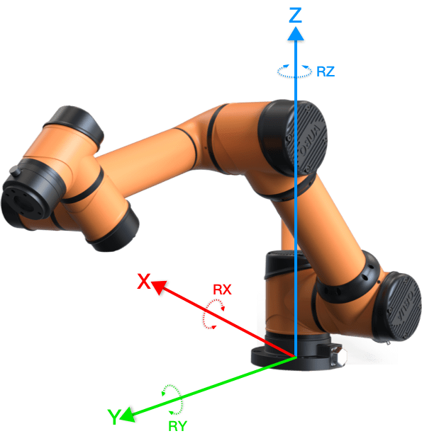
Base coordinate system
The origin of the base coordinate system is at the center of the robot base.
Tool coordinate system
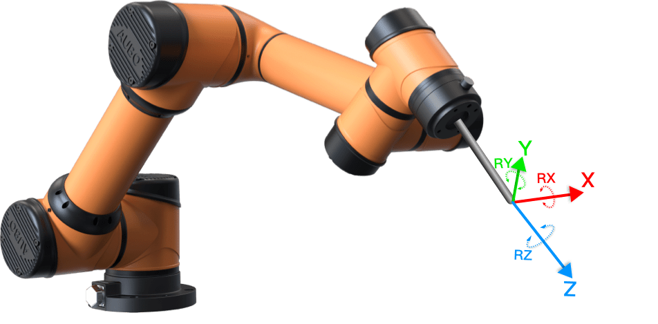
The origin of the tool coordinate system is at the center of the current TCP.
Custom coordinate system
On the "Configure > General > Coordinate System" interface, users can create a new coordinate system in the form of a point, line, or plane. The new coordinate system is positioned by the position of TCP. After selecting the method to create a new coordinate system, users can show the position of the coordinate system by moving TCP to the target position/pose.
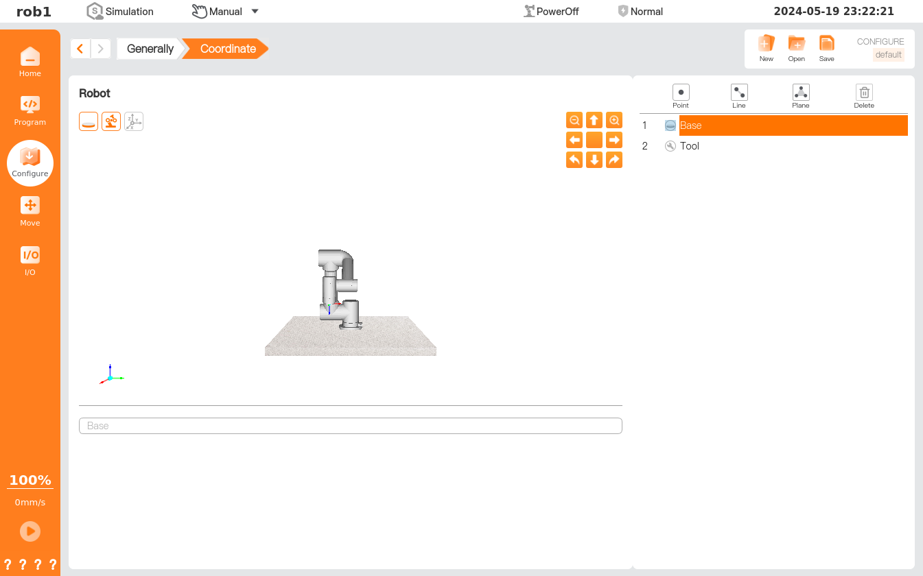
 Point: Create a new coordinate system with points.
 Line: Create a new coordinate system with lines.
 Plane: Create a new coordinate system with planes.
_3@2x.png) Delete: Delete the coordinate system.
Delete: Delete the coordinate system.
1. Create a new coordinate system with points
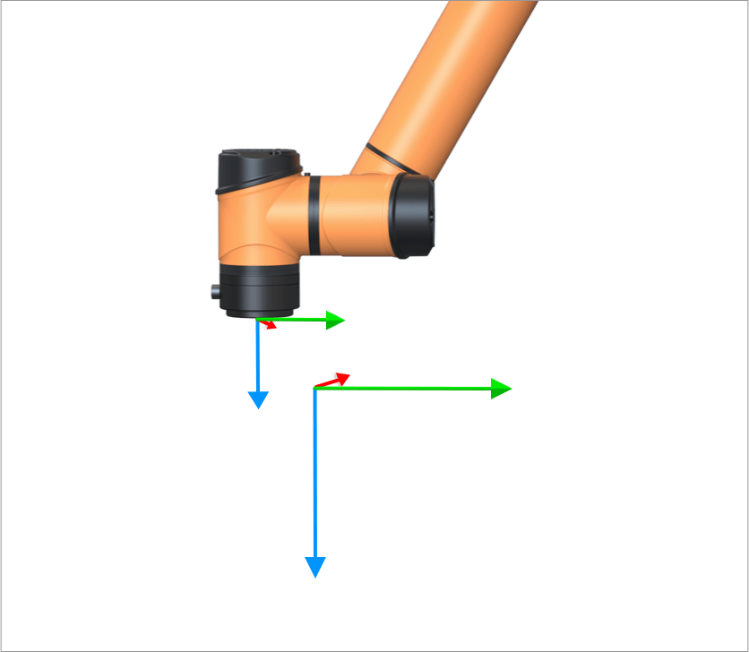
Creating a new coordinate system with points, i.e., showing the position of a new coordinate system origin through TCP, with the coordinate system axes orienting in the same directions as those of TCP. This method is typically used to define a security boundary or global primary configuration for a robot.
Click [Point]
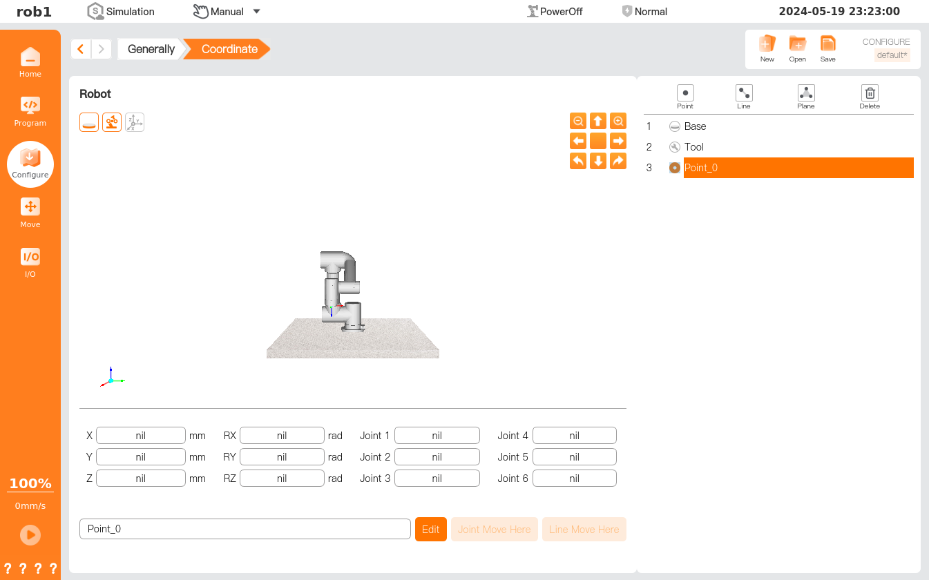
to create a new coordinate system.Click the input box below to rename the newly created coordinate system. Click [Edit], control the robot using the position/pose control button and complete necessary settings, and then click [OK] to save the data and return to the [Coordinate System] page. Pose information used to set the point is displayed below the simulation model.
Click [MoveJ to Here] or [MoveL to Here] to enter the [Move] page, and long press [Auto] to move the robot back to the position/pose used in creating the current coordinate system.
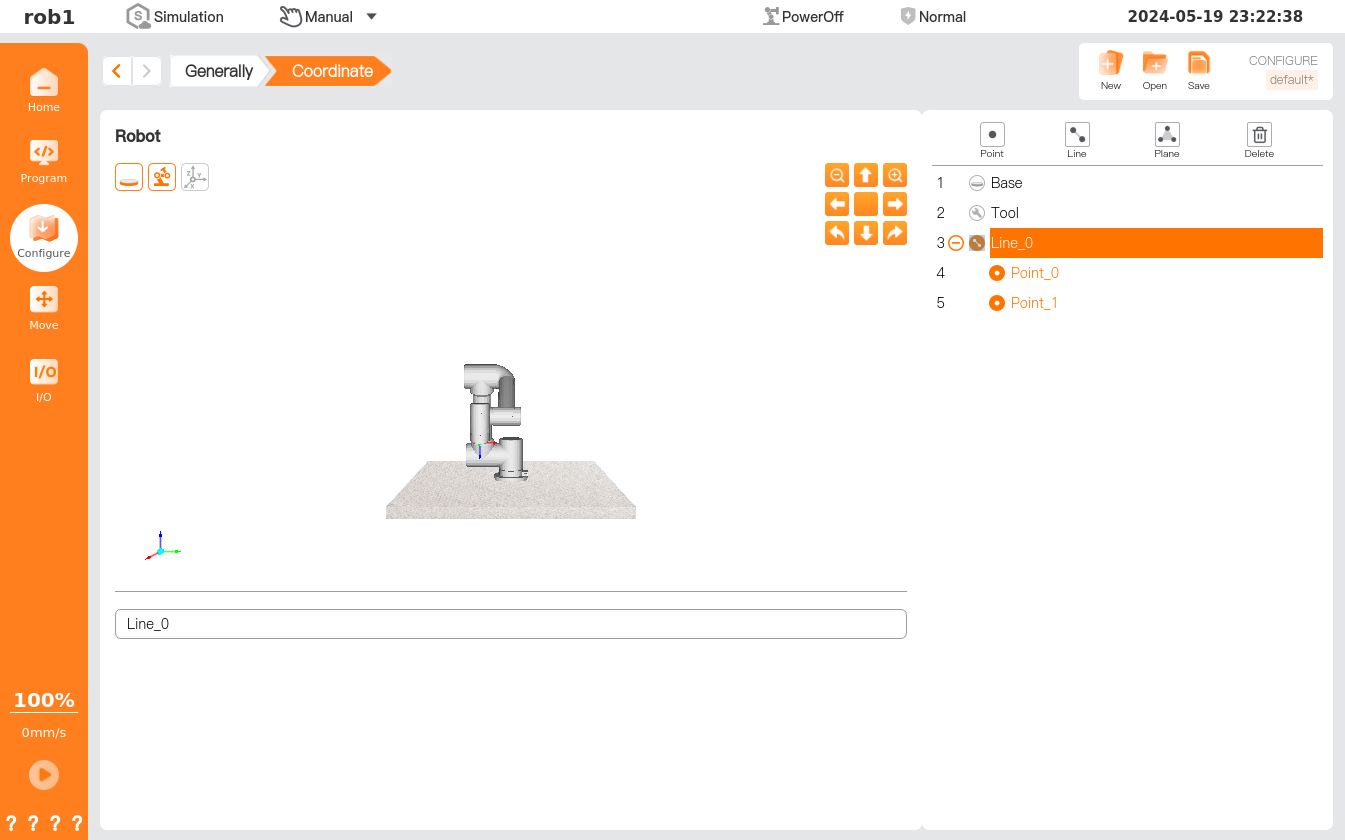
2. Create a new coordinate system with lines
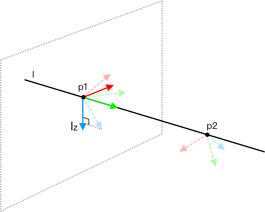
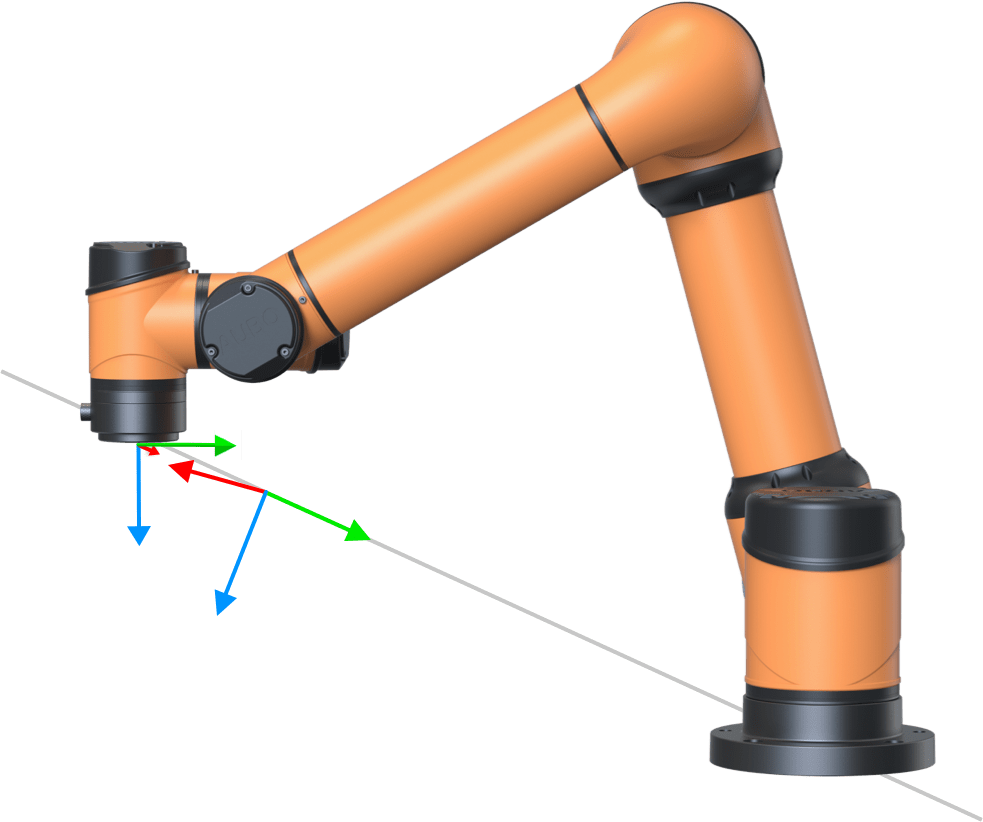
Create a new coordinate system with lines, with the first point as the system origin; The Y axis is a line from the first point to the second point; the Z axis is the projection of the Z axis of the first point on a plane perpendicular to the line. This method defines the moving lines that the robot needs to follow.
Click [Line]
to create a new coordinate system.Click the input box to rename the newly created coordinate system.
Click
 to expand the list, select waypoints one by one, click [Edit], control the robot using the position/pose control button, complete necessary settings, and then click [OK] to save the data and return to the [Coordinate System] interface.
Click [MoveJ to Here] or [MoveL to Here] to enter the [Move] page, and long press [Auto] to move the robot back to the position/pose used in creating the current coordinate system.
3. Create a new coordinate system with planes
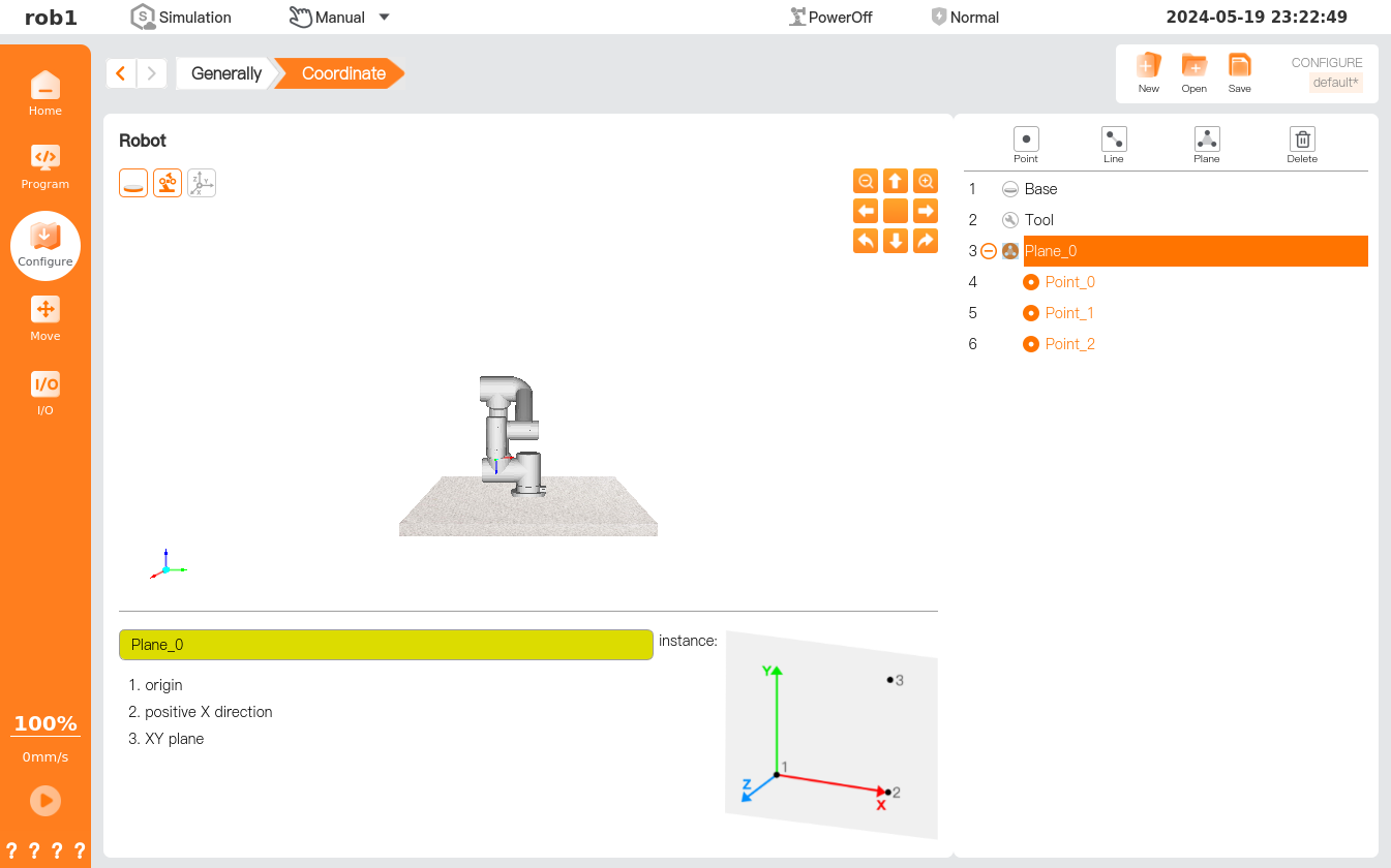
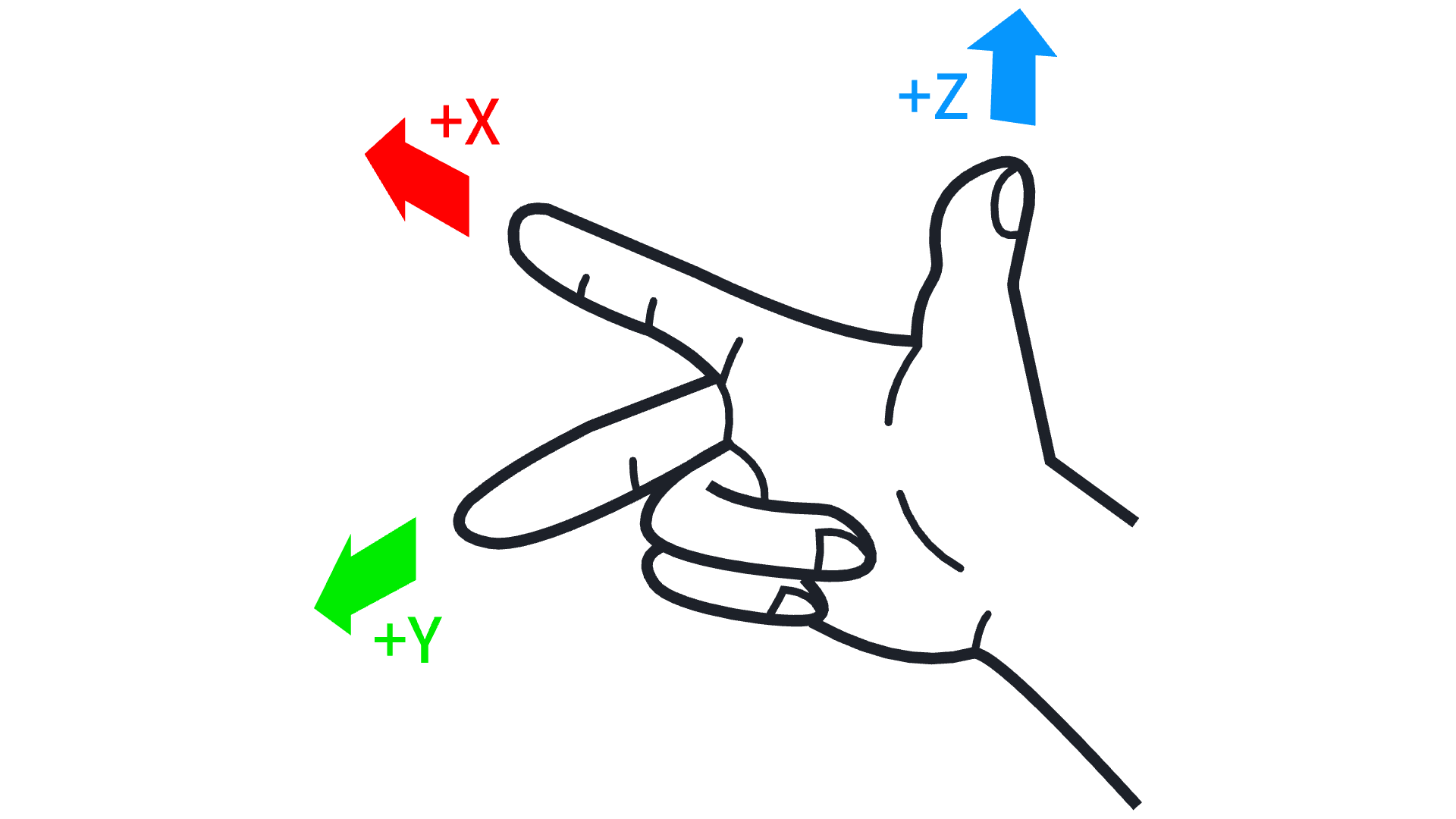
Creating a new coordinate system with planes, also referred to as creating a coordinate system with the three-point plot method, involves taking the first point as the system origin; the X axis is a line from the first point to the second point. The third point falls on the XY plane, with the Z axis perpendicular to the XY plane, satisfying the right-hand rule. This method is generally adopted when a high-precision frame is required, such as when moving the robot relative to a table.
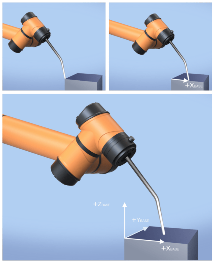
Click [Plane]
to create a new coordinate system.Click the input box to rename the newly created coordinate system.
Click
to expand the list, select waypoints one by one, click [Edit], control the robot using the position/pose control button, complete necessary settings, and then click [OK] to save the data and return to the [Coordinate System] interface.