Payload and TCP
Payload
The payload encompasses the mass of the end load as well as its center of gravity (CoG). When the robot is loaded and unloaded, the robot end load and the CoG will change. To optimize the robot's performance, it is necessary to set the end load and CoG accordingly. The moment of inertia is measured in a specific coordinate system originating at the CoG of the payload, with the axis aligned with the axis of the tool flange. The default inertia can be calculated based on the inertia of a sphere with a user-specified mass and a mass density of 1 g/cm3.
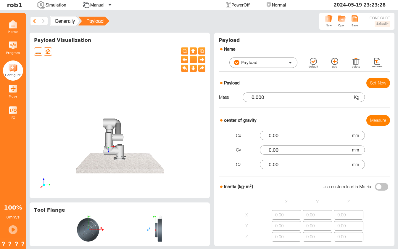
The [Payload] page allows defining or switching a payload. You can define more than one payload, at least one. Each payload must contain parameters such as load mass and CoG to maximize the performance of the robot.
Info
- After the setting is completed, it is recommended to click the [Set Now], [Default], and [Save] buttons successively to ensure that the currently set payload parameters can be used during the move teaching and programming.
- The payload parameters determined as [Default] are to be used during programming.
- The payload parameters determined as [Set Now] are to be used during move teaching.
- The payload parameters determined as [Default] in the installation profile are to be used after shutdown and restart.
- Payload setting priority: Payload set in [Programming] > Payload set in "Configuration > General > Load" > Payload set in "Home > Robot status" functional area.
- Load visualization: Simulate the status of the robot with the current settings.
- Payload: Set up payload, CoG, etc.
- Tool flange: Display the center point of the tool flange.
 Current default: The current payload.
 Default: Set to the default payload.
 Add: Add a new payload.
 Rename: Rename the currently selected payload.
 Delete: Delete the selected payload.
- Set Now: Make the currently set payload effective immediately.
- Measurement: Payload identification wizard, which can guide the user to have the robot automatically calculate the payload and CoG.
Payload setting
- Method 1: Manually enter values for the payload and CoG.
- Method 2: Use the payload identification wizard to determine the payload and CoG.
TCP
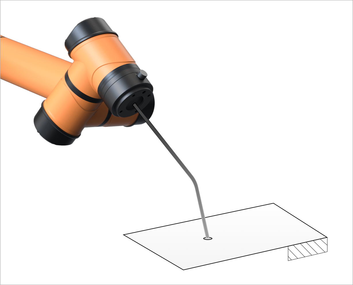
Tool Center Point can be abbreviated as "TCP." Due to the varying shapes and sizes of tools fixed at the end of the robot, such as a welding torch or gripper, it is necessary to select a point representative of the entire tool and take this point as the origin of the tool coordinate system. When moving the robot to a point in space, the essence is to move the TCP to that point, so it can be said that the movement of the robot is equivalent to that of the TCP.
The four-point plot method is usually used to plot four positions to determine the tool coordinate system, including the origin of the system, by changing the joint angle of the robot while the position of the EOAT remains unchanged.
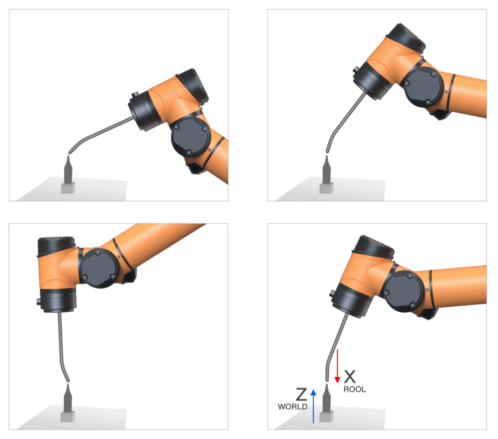
The direction of the tool coordinate system is plotted using the coordinate system of the target and the point-on-plane method.
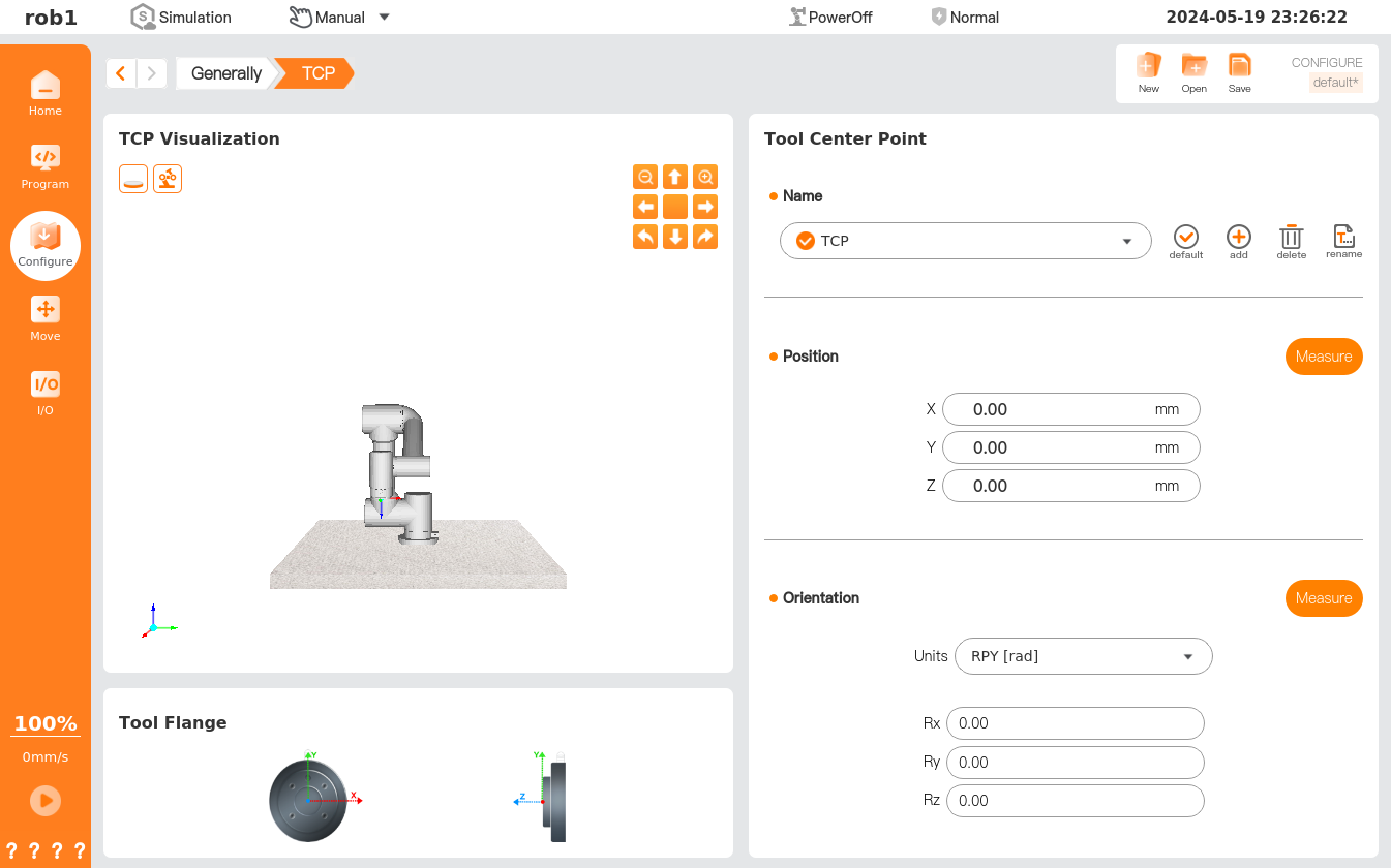
[TCP] page allows setting of tool coordinate system. Each TCP contains translation and rotation parameters set relative to the center of the tool flange: X, Y, and Z coordinates specify the TCP position; RX, RY, and RZ coordinates define the TCP direction. When all values, including direction, are zero, TCP coincides with the center point of the tool flange.
- TCP visualization: Simulate TCP with the current settings.
- TCP: Set up and manage TCP.
- Tool flange: Display the center point of the tool flange.
- Current default: The current default TCP.
- Default: Set to the default TCP.
- Add: Add a new TCP.
- Rename: Rename the selected TCP.
- Delete: Delete the selected TCP.
- Location-Measurement: TCP location recognition wizard, which can guide the user to have the robot automatically calculate the TCP location.
- Direction-Measurement: TCP direction recognition wizard, which can guide the user to have the robot automatically calculate the TCP direction.
TCP setting
- Method 1: Manually enter values for positions X, Y, and Z and directions Rx, Ry, and Rz.
- Method 2: Use the TCP location/direction identification wizard to determine the location and direction of TCP.