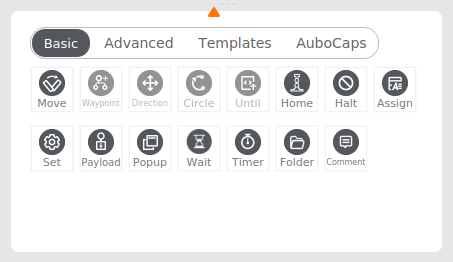
Basic Program Node
Basic program node, namely, the basic node that makes up the program, includes node commands indicating waypoint, direction, comment, folder, etc. For example, the commands indicating waypoint and direction can be used to determine the motion track of the robot. And the commands indicating comment and folder can assist users in managing the program, and their proper use enables good readability of the program.
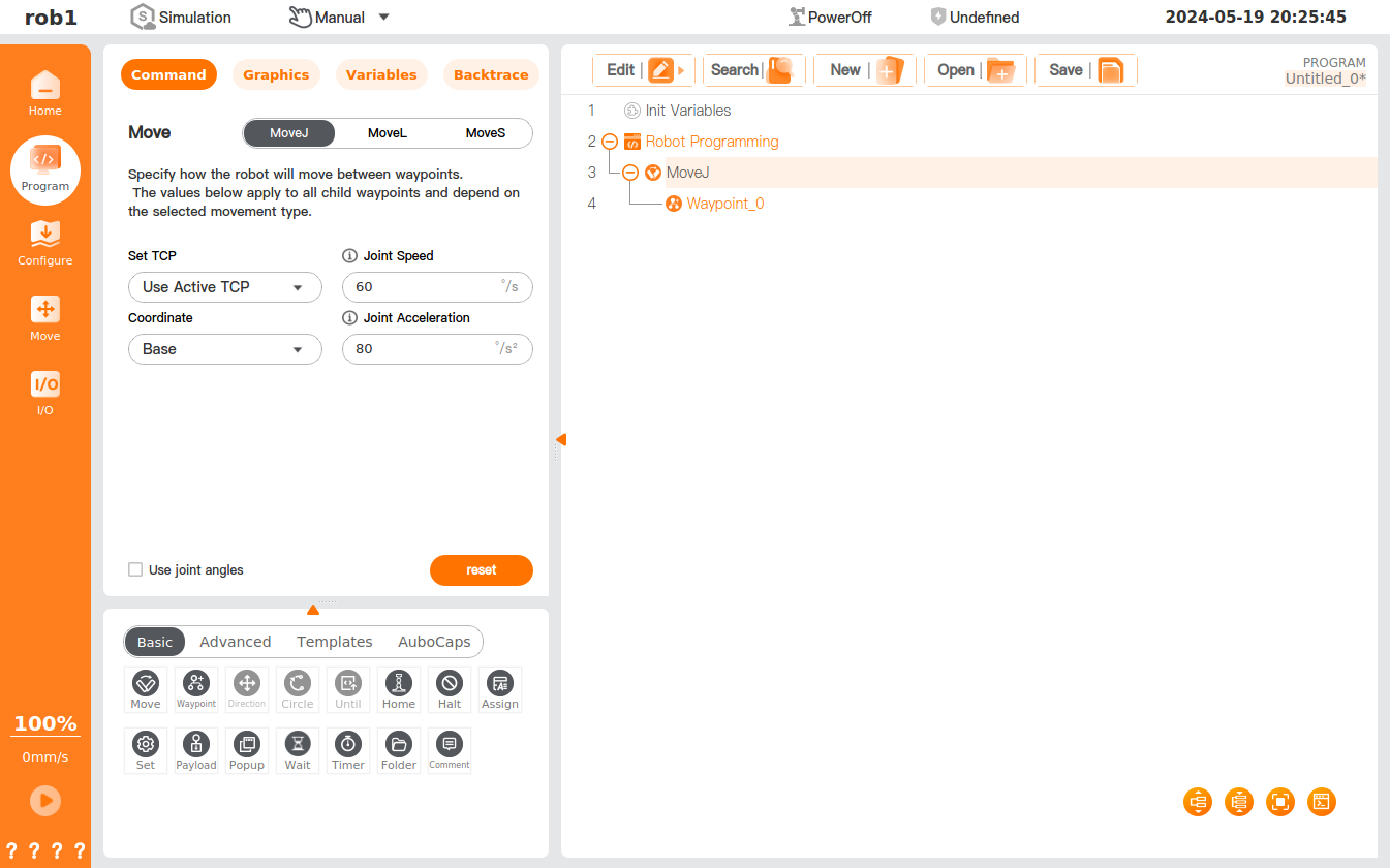
Move
The [Move] node allows you to add a waypoint for the movement of the robot and set the shared parameters of other nodes under the node.
Move type
The robot can move in three modes: MoveJ, MoveL, and MoveS.
MoveJ refers to the movement of the robot by controlling its joint. MoveJ provides a curved path for the tool center point (TCP). If you want the robot to move between waypoints quickly, regardless of the movement path of the TCP between these waypoints, MoveJ should be selected preferentially. MoveJ is suitable for movement in the fastest way in a sufficiently wide environment. This motion mode is as shown in the figure below.
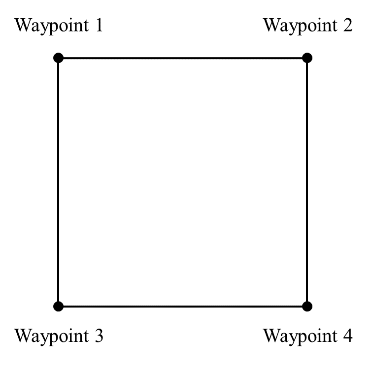
MoveL refers to the movement of the tool center point (TCP) of the robot in a linear way to the target waypoint. This means that each joint moves in a more complex way to keep the TCP on a straight path, and whether the maximum tool speed can be reached and maintained depends on the linear displacement and maximum acceleration parameters. This motion mode is as shown in the figure below.
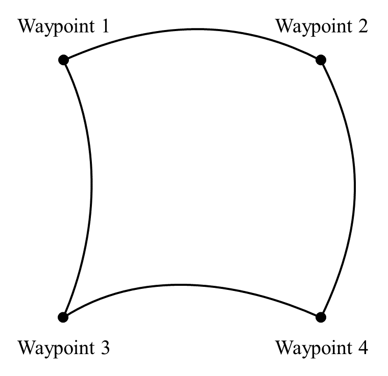
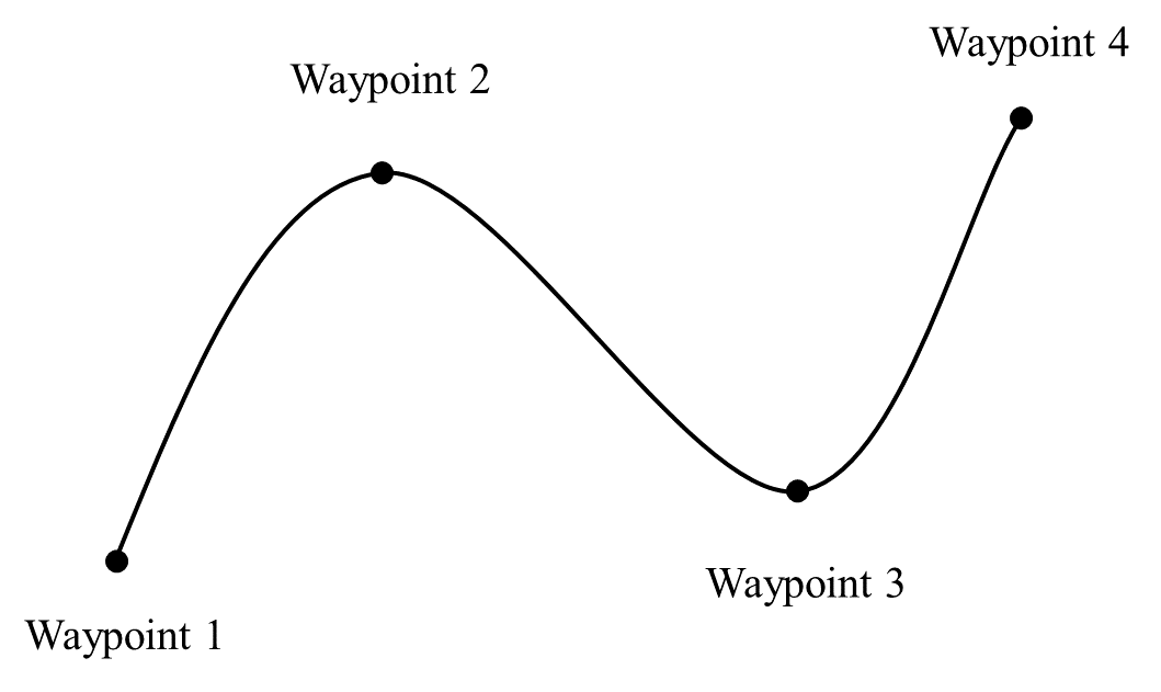
MoveS refers to the smooth movement of the robot through all given waypoints at a constant speed according to a spline curve path established based on the given waypoints. More waypoints given on the intended curve will result in a more desirable curve path.
Tip
- Operator's or I/O operations are not supported during MoveS. Operator's or I/O operations during MoveS may trigger the protective stop of the robot.
- Only [Waypoint] nodes can be included in [MoveS] nodes.
Movement speed
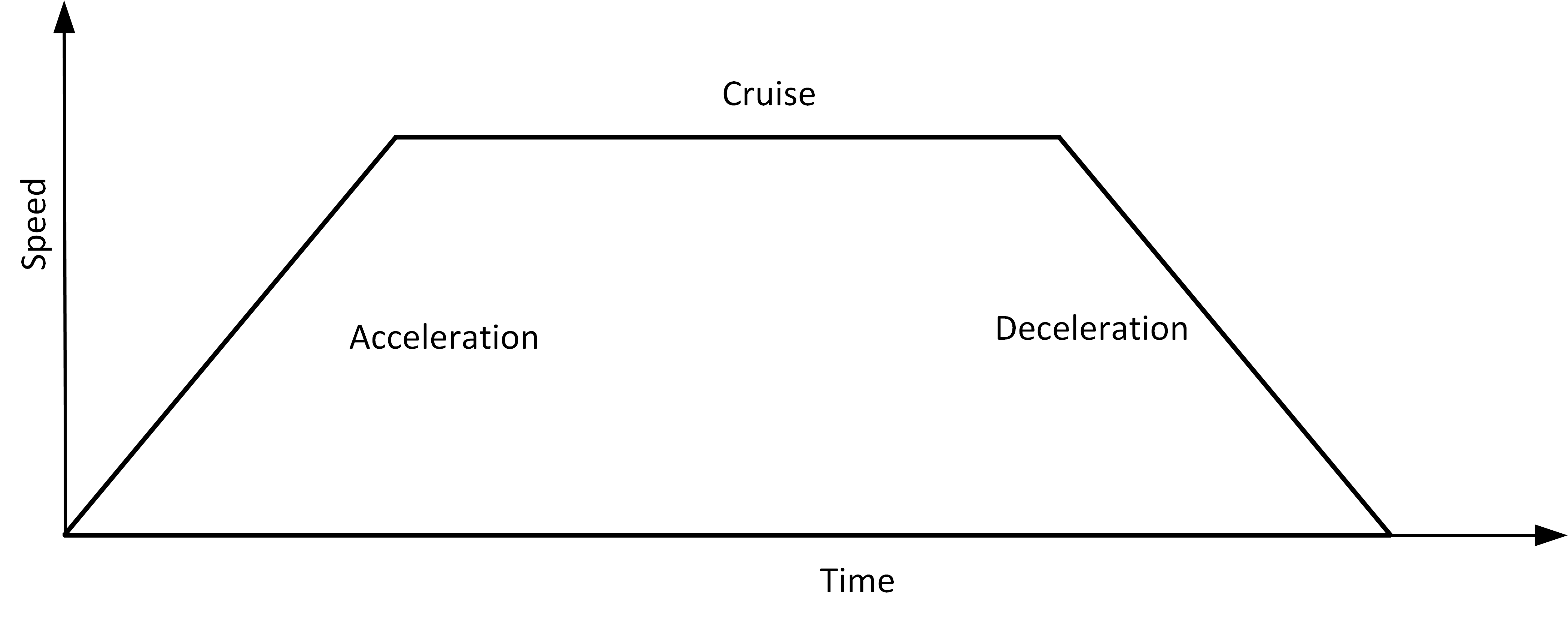
The movement speed curve of the robot is divided into three parts: acceleration, cruise, and deceleration. The movement speed parameter determines the cruise, and the acceleration parameter determines the acceleration and the deceleration gradient, as shown in the figure.
Blend
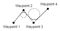
When the robot is moving, if you have set the blend parameters, a smooth transition between the two tracks can be achieved so that the robot can move faster and more stably. For example, in the following figure, the robot is expected to reach [Waypoint_2] from [Waypoint_0], but because there are other items between the two waypoints, the robot has to start from [Waypoint_0] and go through [Waypoint_1] to reach [Waypoint_2]. Since [Waypoint_1] only exists to bypass other items, it is preferable for the robot to expend minimal energy and time at [Waypoint_1]. At this time, adding the blend parameters will enable the robot to smoothly transition from the first track to the second track, eliminating the need for deceleration and acceleration at the intermediate point. This reduces the time and energy required for the robot to turn, thereby enhancing the movement efficiency.
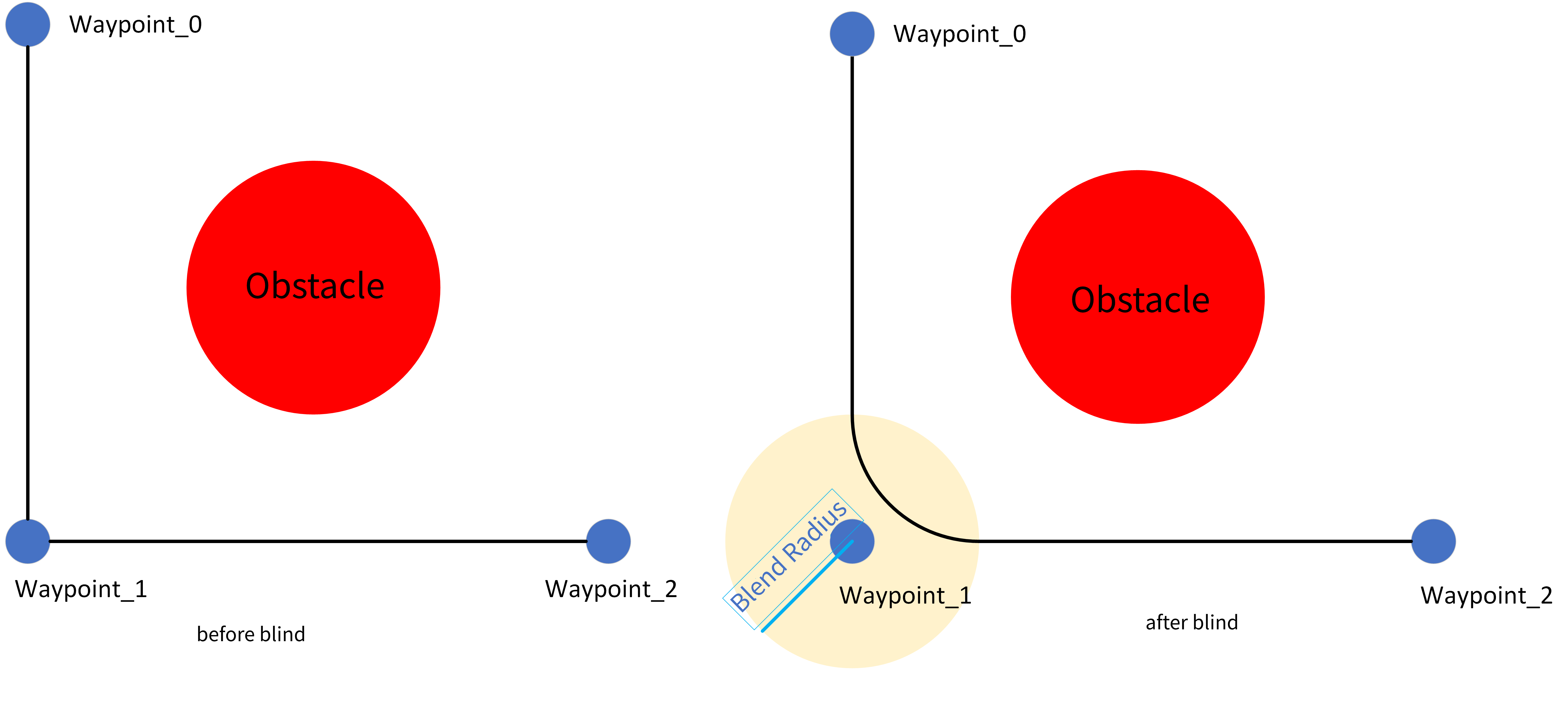
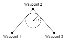
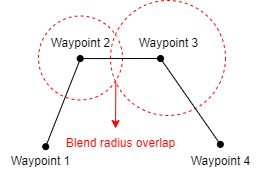
The main blend parameter is the blend radius, that is, the turning radius of the robot. When the robot is within the blend radius of a waypoint, the blend feature may be activated, allowing the robot to deviate from its original path and move continuously without stopping at the waypoint. The smaller the blend radius, the larger the path angle; and the larger the blend radius, the smaller the path angle. Note, however, that overlaps shall be avoided in the blend, as shown in the figure below.
Other parameters that affect the blend track:
- Movement type (MoveJ, MoveL, MoveS) at the starting and ending positions of blend.
- Robot movement time on the track.
- Robot speed (joint speed/joint acceleration, tool speed/tool acceleration).
Blend track
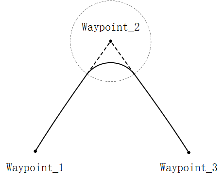
Blend in [MoveJ]: After the blend parameters are set, the system will generate a smooth curve in the joint space.
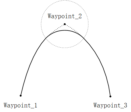
Blend in [MoveL]: After the blend parameters are set, an arc path will be planned at the blend position, following a direction blended with the smooth interpolation between the two tracks.
Shared parameter
The shared parameter feature enables bulk setting of parameters in this program block. For example, after setting [Shared parameter] in the [Move] node, all nodes added to the [Move] program block will, by default, apply the values set in the [Move] node for any parameters included in [Shared parameters], unless those parameters are specifically set.
Coordinate system
As the robot moves, the software calculates the position of the TCP within the selected coordinate system, so the motion track of the robot may vary with the coordinate system selected. Two coordinate systems, for the base and one for the tool are predefined, and users can also select a custom coordinate system here. Please refer to "[Coordinate system](../02_basic_operation/05_coordinate.md#Custom coordinate system)" for the description and settings of the coordinate system.
Tool center point (TCP)
Select a different tool center point (TCP) to adjust the movement mode of the robot between waypoints. The TCP for [Waypoint] can be set in the [Move] node. See TCP for the description and settings of TCP.
- Use active TCP.
- Ignore active TCP, allowing adjustment of the movement in relation to the tool flange.
- Custom TCP.
Use joint angles
If this option is checked, the joint angles will be recorded in the scripts when the program is running, replacing the location information of the robot. And the system will disable the [Set TCP] and [Coordinate] here. If this feature is activated, the waypoint information will remain unchanged during project migration, allowing the robot to continue using the data without adjustment.
Add [Move] node
- Click the [Move] icon to add a [MoveJ] node to the program tree, including a [Waypoint] node beneath it.
- The [Move] node contains movement types such as MoveJ, MoveL, and MoveS. The display name of the [Move] node in the program tree is determined by the movement type you select.
- Select the [MoveJ/MoveL/MoveS] node to set the node.
Add [MoveS]
- Click the [Move] command to add a [Move] node to the program tree.
- Select [MoveS] in the [Move] command interface.
- Set the relevant parameters of the MoveS: TCP, coordinate, joint speed, joint acceleration, etc.
- Under the [MoveS] node, add several [Waypoint] nodes and configure the location for each waypoint to finalize the [MoveS] addition.
Waypoint
The [Waypoint] command indicates the target position for the tool center point (TCP) of the robot. By configuring the waypoint, the precise location of the robot can be established. Generally, the motion track of the robot's tool center point (TCP) includes two or more waypoints. The [Waypoint] node enables the configuration of [FixedPos], [Variable Pos,] and [Relative Pos.]
Tip
The [Waypoint] node must be placed under the [Move] node.
1. Fixed pos
The [Fixed Pos] feature enables configuration of the position/pose of the [Waypoint] by operating the robot's [Move] interface or dragging the robot.
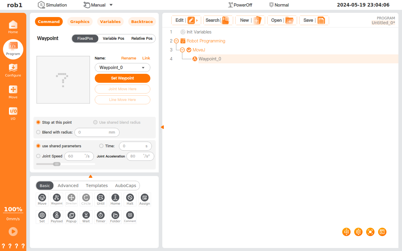
Teach: You can guide the robot to assume a specific position/pose in the current coordinate system. Below is the procedure for teaching a waypoint to a robot:
Add a [Move] program node to the program tree.
Set TCP via the [Set TCP] drop-down menu in the [Move] program node; select a coordinate system via the [Coordinate] drop-down menu.
Insert a [Waypoint] node under the [Move] program node. After insertion, select the waypoint type in the upper right of the [Waypoint] node interface.
Click [Set Waypoint] in the [Fixed Pos] interface to access the robot teaching interface, where you can use the [Position/Pose Control] to move the robot or enter the HandGuide mode to manually guide the robot to the target waypoint. After setting, click [OK] to save the position/pose of the [Waypoint.]
[Waypoint] naming and switching
- A waypoint is named "waypoint_n" by default, with n starting at 0 and incrementing by 1 for each new waypoint.
- Rename waypoint: Click [Rename] to change the waypoint name. Waypoints with duplicate names are not allowed.
- Link: Click the icon
 or [Link] and select the waypoint in the program to use the position/pose of the target waypoint. After successful linking, the [Link] button will change to [Cancel Link]. Click [Cancel Link] to restore the original waypoint.
Blend parameters
- [Stop at this point]: You can set the blend radius to 0 mm to stop the robot at this waypoint position.
- Use shared blend radius: You can set the waypoint to use a shared blend radius (this option is not selectable in MoveJ and MoveS modes).
- Blend with radius: You can set the blend radius for the waypoint.
Speed
- Use shared parameters: You can set the waypoint to use shared speed parameters (joint/tool speed, joint/tool acceleration).
- Time: You can set the total movement time (in seconds) from the last waypoint to this waypoint, which affects the speed of the robot. An unreasonable total movement time may cause out-of-range motion parameters of the robot, which will be optimized by AuboStudio, and the operating parameters of the robot shall prevail.
- Joint/tool speed, joint/tool acceleration: You can set the joint/tool speed and joint/tool acceleration of the waypoint.
2. Variable pos
The [Variable Pos] option allows you to set the position/pose of [Waypoint] by configuring variables. The [Variable Pos] option is often used for bulk setting of the parameters for identical waypoints to save programming time.
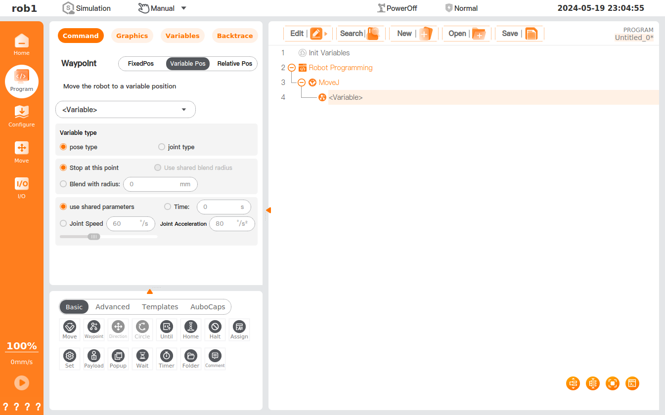
- Select a variable: Click the [Variables] dropdown box to select the variable. Please refer to "Assignment" and "Variables" for the settings of variables.
- Variable type: You can set the type of the variable.
- Joint type: The six parameters of the variable correspond to the joint angles of the robot, measured in radians (rad).
- Example:
i_variable_1 = {0, -0.261796, 1.74532, 0.436316, 1.5708, 0}.
- Example:
- Pose type: The six parameters of the variable represent the Cartesian pose of the robot's end-effector, formatted as {x, y, z, roll, pitch, yaw}:
- The first 3 parameters (x, y, z) are the position coordinates of the end-effector in the world coordinate system, with the unit of meters (m);
- The last 3 parameters are the end-effector orientation angles (Roll, Pitch, Yaw, i.e., RPY Euler angle representation), measured in radians (rad).
- Example:
i_variable_1 = {0.548871, -0.1215, 0.263199, 3.14159, 0, 1.5708}.
Pose expression notation:
The pose uses Roll-Pitch-Yaw (RPY) Euler angle representation.
Rotation sequence (fixed axis): X→Y→Z, which means: first rotate around the X-axis of the fixed coordinate system by
(roll angle), then around the Y-axis by (pitch angle), and finally around the Z-axis by (yaw angle). The corresponding total rotation matrix is:
Where
, , and are the basic rotation matrices about the X, Y, and Z axes respectively. Rotation around fixed axis X→Y→Z and rotation around moving axis Z→Y→X result in mathematically equivalent total rotation matrices.
- Joint type: The six parameters of the variable correspond to the joint angles of the robot, measured in radians (rad).
3. Relative pos
The [Relative Pos] feature defines the position/pose of the [Waypoint] by the gap between two given locations (source waypoint and target waypoint).
Tip
In programming, it is essential to include at least one waypoint in addition to the [Relative Pos] waypoint; failing to do so may result in unpredictable errors in the robot's operation.
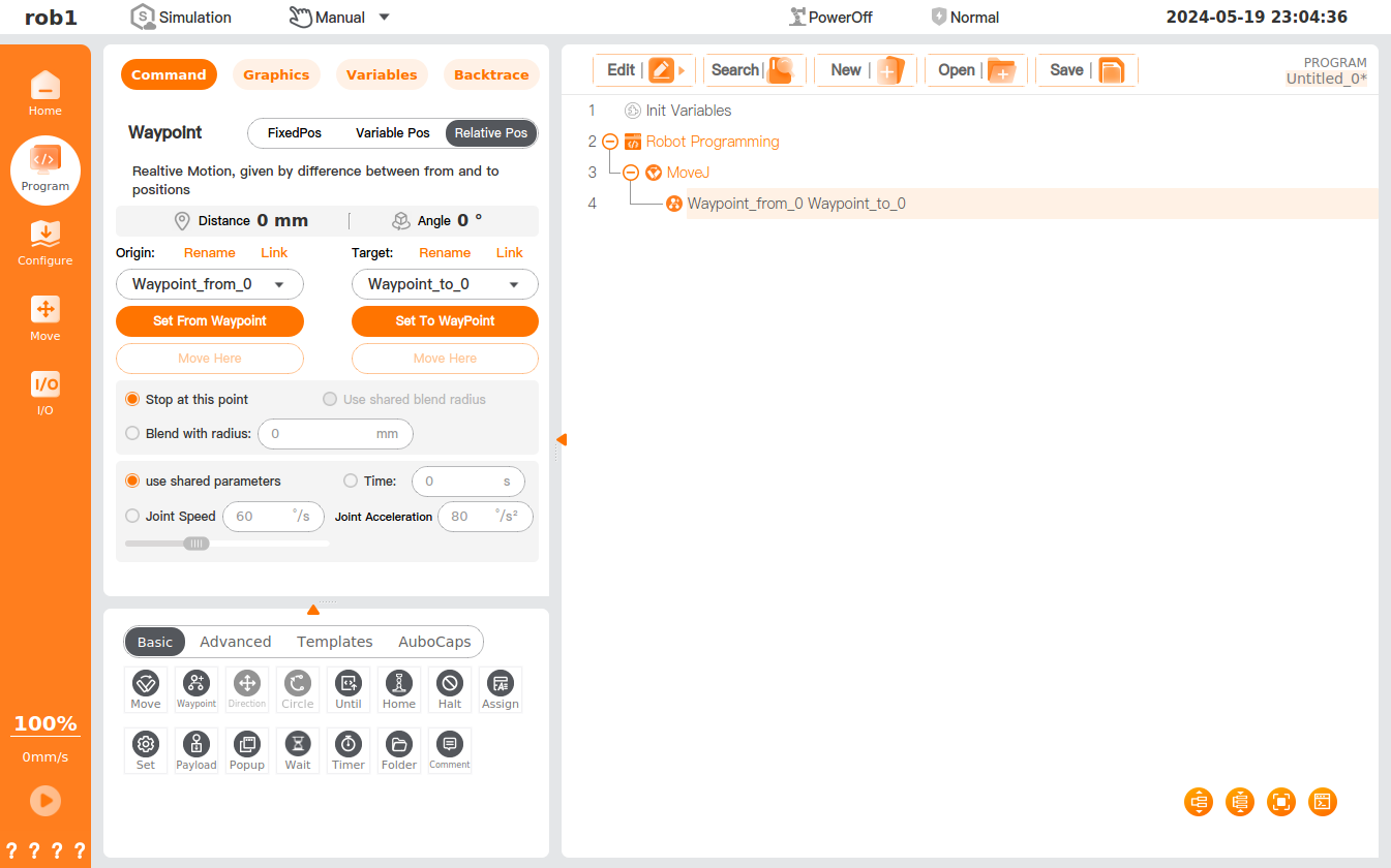
Distance: the Cartesian distance between the source and target waypoints.
Angle: the length of the rotational vector for direction change between the source and target waypoints.
[Waypoint] rename and selection
- Click [Rename] or the waypoint name to rename the source waypoint or target waypoint.
- Click [Link] or the icon to expand the waypoint list and select a waypoint. After successful linking, the [Link] button will change to [Cancel Link]. Click [Cancel Link] to restore the original waypoint.
Set source waypoint and target waypoint: Click to access the robot teaching interface, where you can use the [Position/Pose Control] to move the robot or enter the HandGuide mode to manually guide the robot to the target waypoint. After setting, click [OK] to save the position/pose of the source or target waypoint.
Move here: click to access the [Move] interface, where you can press and hold [Auto] to move the robot to the position/pose of the waypoint.
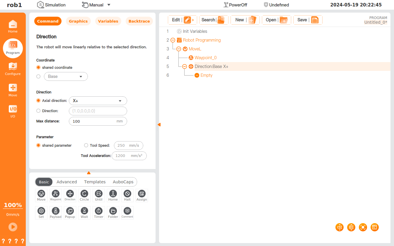
Direction
The [Direction] command specifies the motion relative to the coordinate system or TCP so that the robot can move relative to the specified direction until the stop condition of the [Until] command is met or the maximum distance set in [Direction] is reached.
Tip
- The [Direction] feature must be used under the [MoveL] command.
- The [Direction] command should be used with the [Until] command.
Settings
Coordinate: You can set the coordinate system used for motion at this node. You can use a shared coordinate system for the [Move] node or a custom coordinate system.
Direction: You can set the movement direction of the robot under the specified coordinate system, which can be the axial direction of the coordinate system or the custom direction.
Max distance: You can set the maximum distance the robot can run in the direction.
Tip
If the distance for the stop condition of the [Until] command is greater than the [Max distance], the [Max distance] will be the maximum extent of the motion.
Shared parameter: using the relevant parameters set in the [MoveL] node. Users can also define the values of [Tool Speed] and [Tool Acceleration] in the [Direction] node.
Add [Direction]
- Click [Move]
 under the [Basic] program node to add the [Move] node to the program tree and set the [Move] node to [MoveL].
 - Click [Direction]
 under the [Basic] program node to add a [Direction] node under the [MoveL] node.
 - Select [Direction] in the program tree, and set the parameters in the [Command] interface.
- Users can add [Until]
 to set the stop condition for movement in the direction. Please refer to "Until" for the [Until] command.
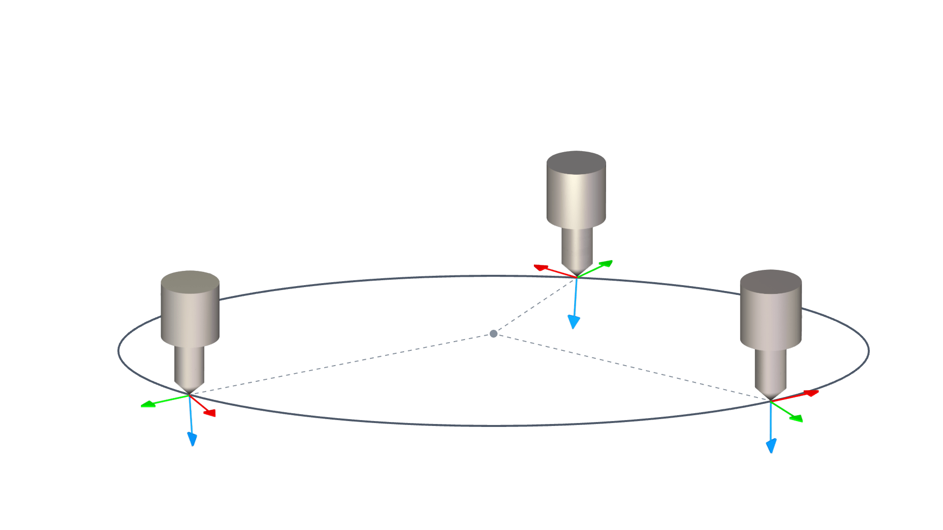
Circle
The [Circle] command positions the TCP at the end of the robot, enabling it to move in an arc or a circle at a constant speed. The arc or circle is defined by a three-point method, with the robot moving sequentially from the starting waypoint to the ending waypoint to establish the Cartesian trajectory planning. When the robot moves in an arc or a circle, the starting and ending points will affect the pose change of the robot, and the maximum speed and acceleration in the movement process are similar to those in linear motion.
Tip
- The [Circle] node needs to be used under the [MoveL] command.
- The three points that form a circle must not be collinear; otherwise, the system will display an error message in a pop-up window.
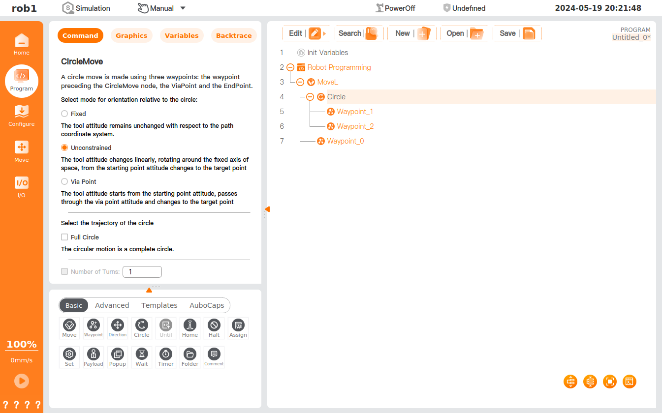
Settings
The [Circle] node requires setting of three waypoints: the starting point (waypoint _0), the ViaPoint (waypoint _1), and the EndPoint (waypoint _2). By default, all waypoints use the same blend radius. Please refer to "Move" for a description of the blend. As TCP passes through each waypoint at a constant speed, the robot will not wait for I/O or the operator's operations. At that time, I/O, or the operator's operation, may cause a protective stop of the robot.
Select a mode for orientation relative to the circle (the mode defines the orientation of the tool):
Fixed: The tool pose remains unchanged with respect to the arc path coordinate system.
Set position/pose Actual position/pose 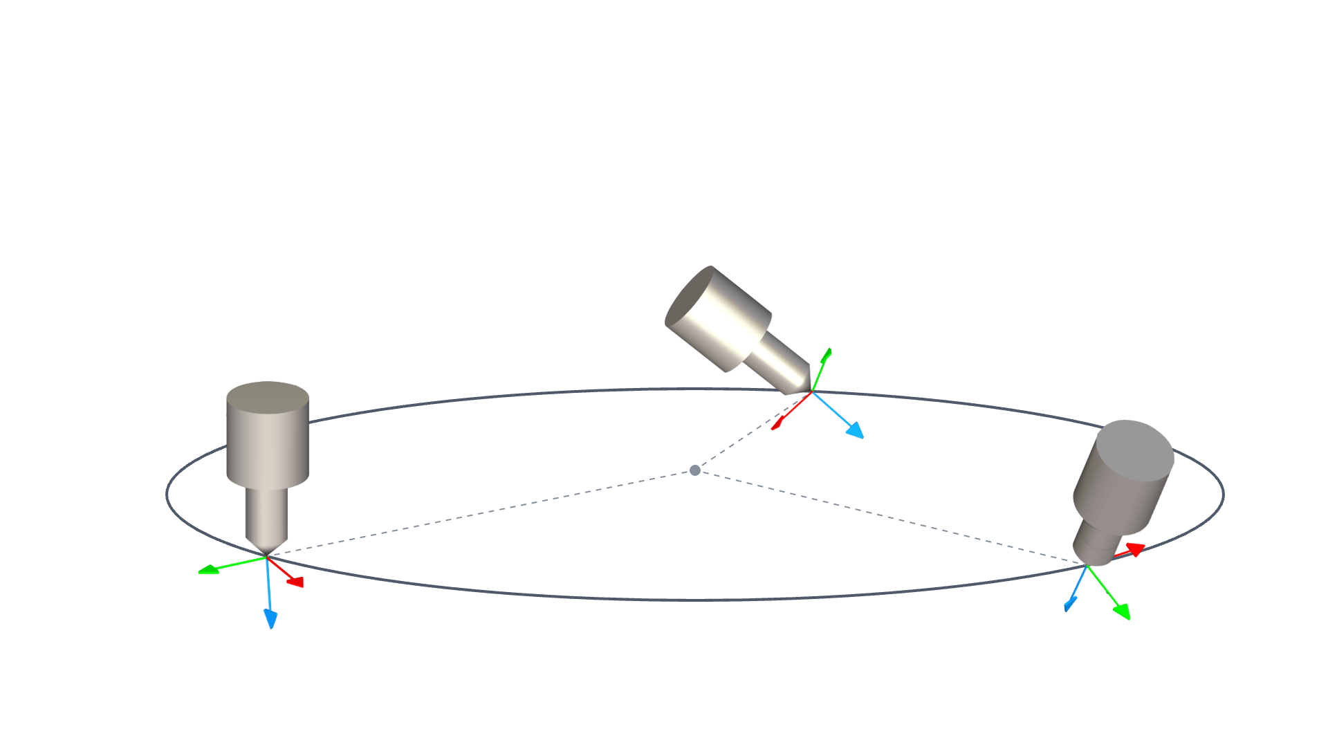
Unconstrained: The tool pose changes linearly, rotating around the fixed axis of space, transitioning from the starting point pose to the target point pose.
Set position/pose Actual position/pose 
Via Point: The tool pose starts from the starting point pose, passes through the via point pose, and changes to the target point pose.
Set position/pose Actual position/pose
Select the trajectory of the circle
- Full Circle: When this option is checked, the robot will move in a complete circle determined by the three-point method. When this option is unchecked, the robot moves in a circle between the starting point, the via point, and the end point and returns to the starting point in a straight line after reaching the end point.
- Number of Turns: You can set the number of turns for a complete circle motion.
Until
The [Until] command sets the motion stop condition. Multiple stop conditions can be added for a single action. When the first stop condition is met, the motion stops. Users can add the [Until] node under the [Direction] node or the [Waypoint] node to set the stop condition of the robot.
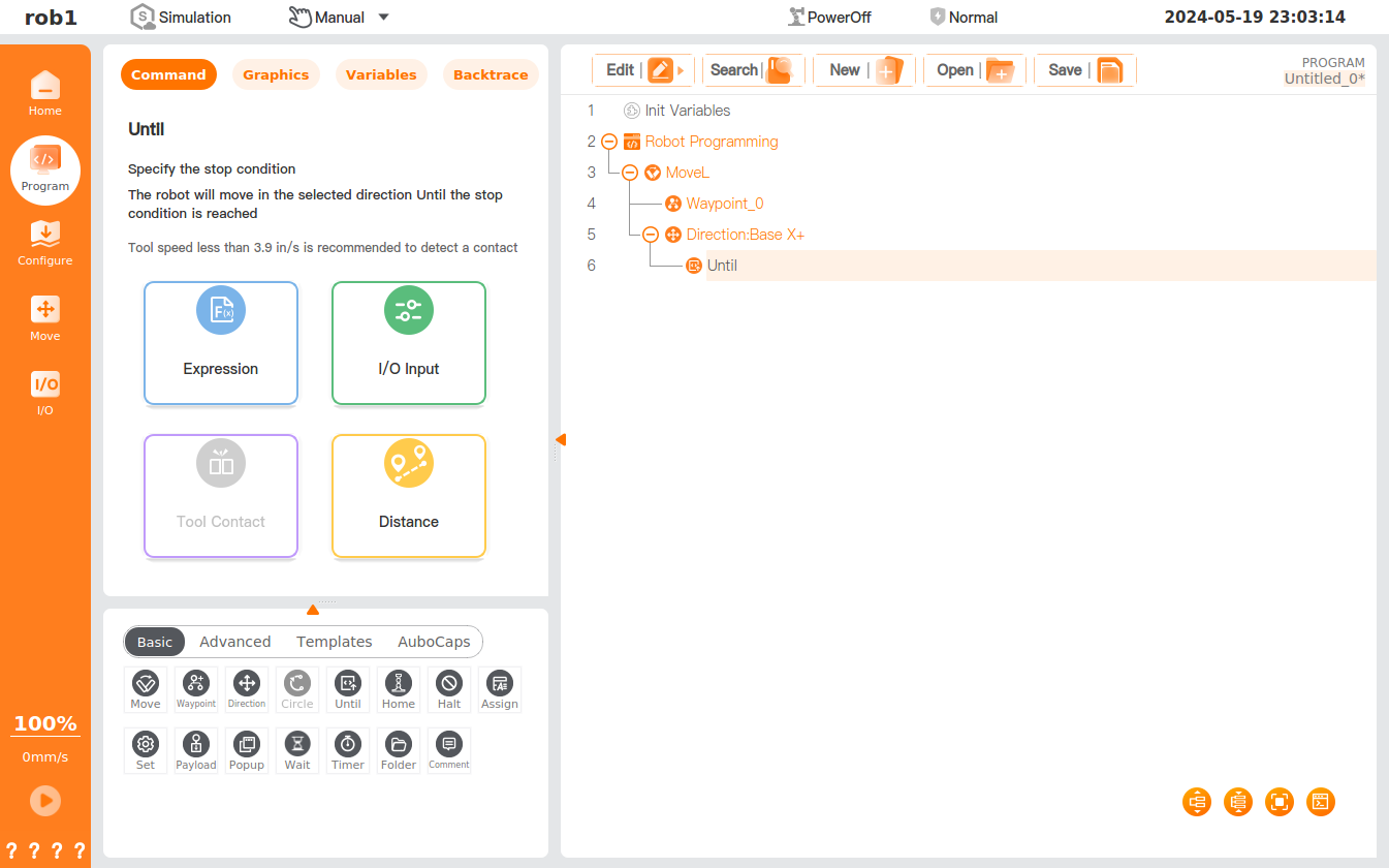
Set stop condition
Expression: I/O, a variable or a script function is defined as the stop condition, and the robot will stop when the condition of the expression is met.
Tool Contact: The robot moves until an impact on the tool is detected and stops at a defined deceleration.
Tip
The default movement speed is too fast for contact detection. A faster movement speed can cause the robot to collide, triggering a protective stop, before the tool contact condition takes effect. - To avoid triggering a protective stop, a tool speed of less than 3.9 mm/s2 is recommended.
I/O Input: The [Until] stop feature of the robot is triggered by a digital input or an analog input. For example, if [Until] digital input DI02 is set at a low level, the robot will stop when it receives a low-level signal of DI02.
Distance: The robot moves along the specified direction and stops at [Distance].
- Stop at this point: The robot will stop after reaching the waypoint.
- Blend with radius: If there are other waypoints after the node, the robot will not stop but run smoothly to the next node.
Reach waypoint: This option appears when [Until] is inserted directly under the [Waypoint] node, and other actions can be added to the [Until Reach] node. When the robot reaches the [Waypoint] node, it performs the actions in the [Until Reach] node.
Add action: When this option is checked, you can add an action when the [Until] condition is met. If this option is not defined, the program executes the next node in the program tree.
Assignment
The [Assignment] command assigns a program variable with a value. It assigns the selected variable with the value of the expression or with the value entered by the machine operator.
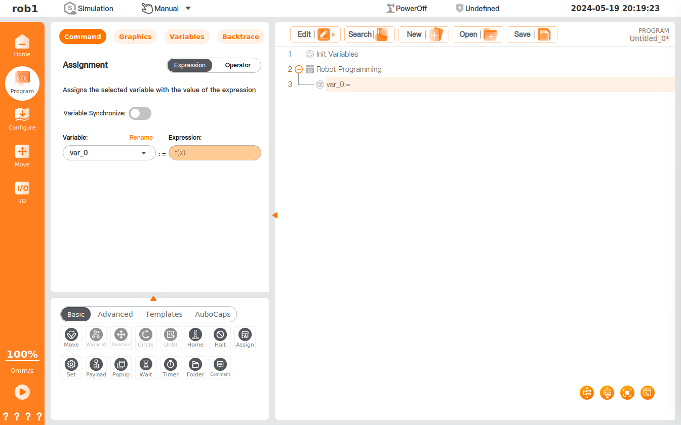
Set assignment type
Expression: You can set the variable to an expression or create a new variable.
Operator: You can set the type of input variable; when the program runs to this node, the operator needs to manually input the variable for value assignment.
- Operator prompt: You can add prompts to help the operator enter the correct variable.
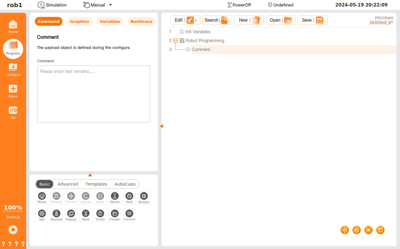
Comment
The [Comment] command is designed to help users record the comment information, and the comment text will not be displayed when the program runs.
Popup
The [Popup] command allows you to specify a message, which will be displayed on the screen when the program runs to the node.
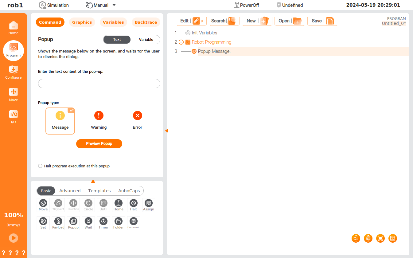
Settings
- Text: Inputting the text information and clicking [Preview Popup] to view the popup effect. The text popup is divided into three types: message, warning, and error.
- Variable: You can select the variables, and when the program runs to the node, the value of the selected variable will be given in a popup, waiting for the user to dismiss the dialog. The variable popup is divided into three types: message, warning, and error.
- Halt program execution at this popup: If this option is checked, when the program runs to the [Popup] node, a message will be displayed in a popup on the screen, and the program execution will be halted.
Settings
The [Set] command allows you to add the action you wish the robot to perform at this point in the program.
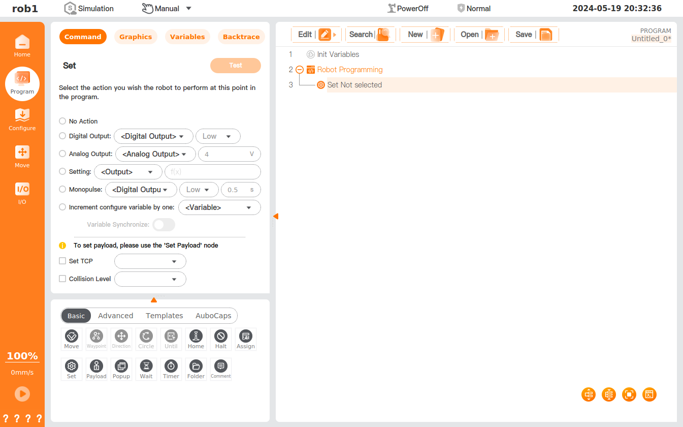
No Action: No operation.
Digital Output: You can set the digital output signal here.
Analog Output: You can set the analog output signal here.
Setting: You can set the expression of the digital or analog output. Only true/false or 1/0 is supported by the digital output port, where only 1/0 is supported by the Modbus port.
Monopulse: You can set the time for the digital output port to continuously output high/low levels.
Increment configure variable by one: The configure variable is incremented by one automatically. Please refer to "Variables" for the settings of the configured variable.
Variable Synchronize: Please refer to "Synchronization" in "Assignment".
Set TCP: You can select the TCP here. Please refer to "TCP" for the creation and settings of TCP.
Collision Level: You can set the collision level here.
Test: The settings of this node are performed once. When [Setting] or [Increment configure variable by one] is selected, the node cannot be tested.
Timeout Termination:
- When this option is checked and a non-zero time is set, if the bus write operation is not completed within the set time, the program will be terminated immediately and a runtime error pop-up will be displayed.
- When unchecked or the time is set to
0.00s, the operation returns directly without checking whether the write was successful.
Note
- Usage: This extended option [Timeout Termination] is only available when the output is set to a Modbus address.
- Value Range:
0 ~ 86400.00s(maximum timeout of 24 hours).
Payload
The [Payload] command allows you to select an existing payload or select [Custom Load] to enter a value. See "Payload" for the settings of the existing payload.
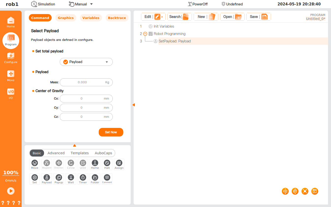
Settings
- Set Now: click to execute the setting of the node once.
Tip
Payload setting is required for picking up and releasing materials by the robot.
Wait
The [Wait] command allows you to set the waiting time or digital input signal.
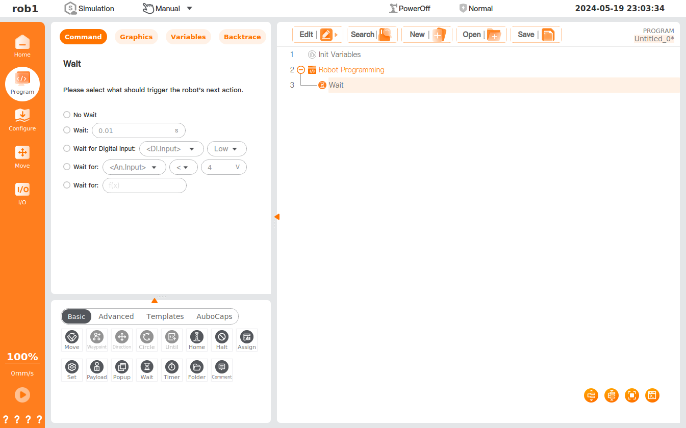
Settings
- No wait: When this option is checked, the robot will not wait.
- Wait: The robot is programmed to wait for the set duration before resumed operation.
- Wait for Digital Input: The robot is programmed to wait for the set digital signal before resuming operation.
- Wait for Analog Input: The robot is programmed to wait for the set analog signal before resuming operation.
- Wait for the expression: The robot is programmed to wait for the expression to be established before resuming operation.
Timer
The [Timer] command is designed to record the execution time of the program, which will be displayed in the [Variable] interface.
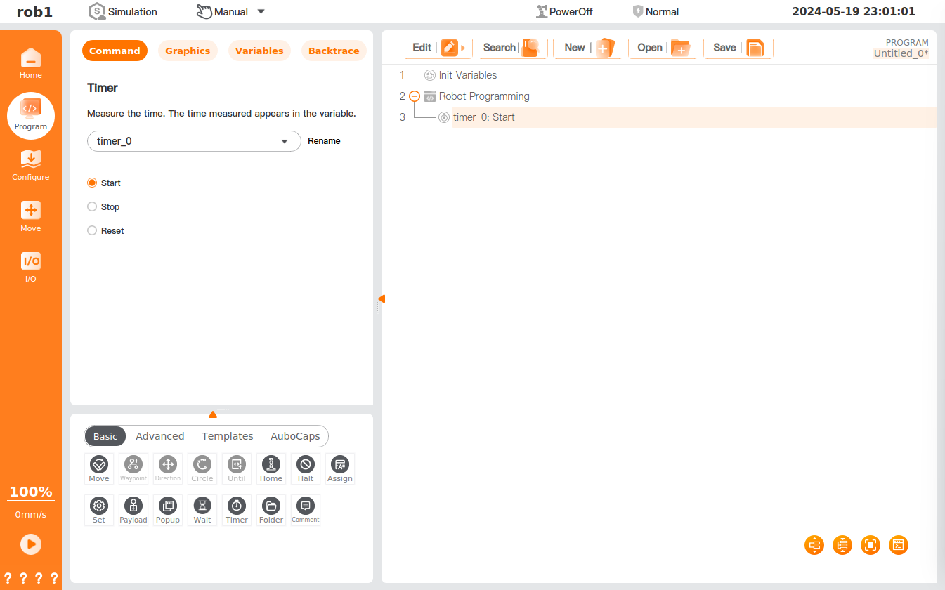
Settings
- You can select a timer in the dropdown box in the [Timer] interface or select [New] in the dropdown box to create a new timer.
- The timer is named "timer_0" by default, and the default value is incremented by 1 each time a new one is created.
- Rename: click to customize the timer name.
- [Timer] status
- Start: You can start the timer here.
- Stop: You can stop the timer here.
- Reset: You can reset the timer here.
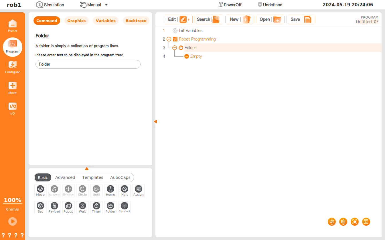
Folder
The [Folder] command is used to organize the program and allows you to add annotations to a program to enhance the clarity of the program tree, making it more readable and navigable. The folder has no effect on the program and its execution.
Settings
- Textbox: Enter text in the textbox, and the text will be displayed in the program tree.
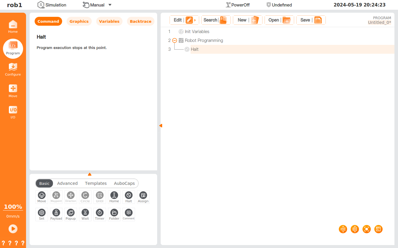
Halt
The [Halt] command is designed for stopping the program's execution. The program stops after reaching the [Halt] node.
Home
The [Home] command is designed to move the robot to the home node. Please refer to "Home" for position setting of the home node. If the corresponding safety I/O is set: when the robot moves to the Safe Home position and keeps stopping, the safety I/O will output a "1" signal; if the robot does not stop at the Safe Home position, the safety I/O output is "0." See I/O Configuration for the settings of safety I/O.
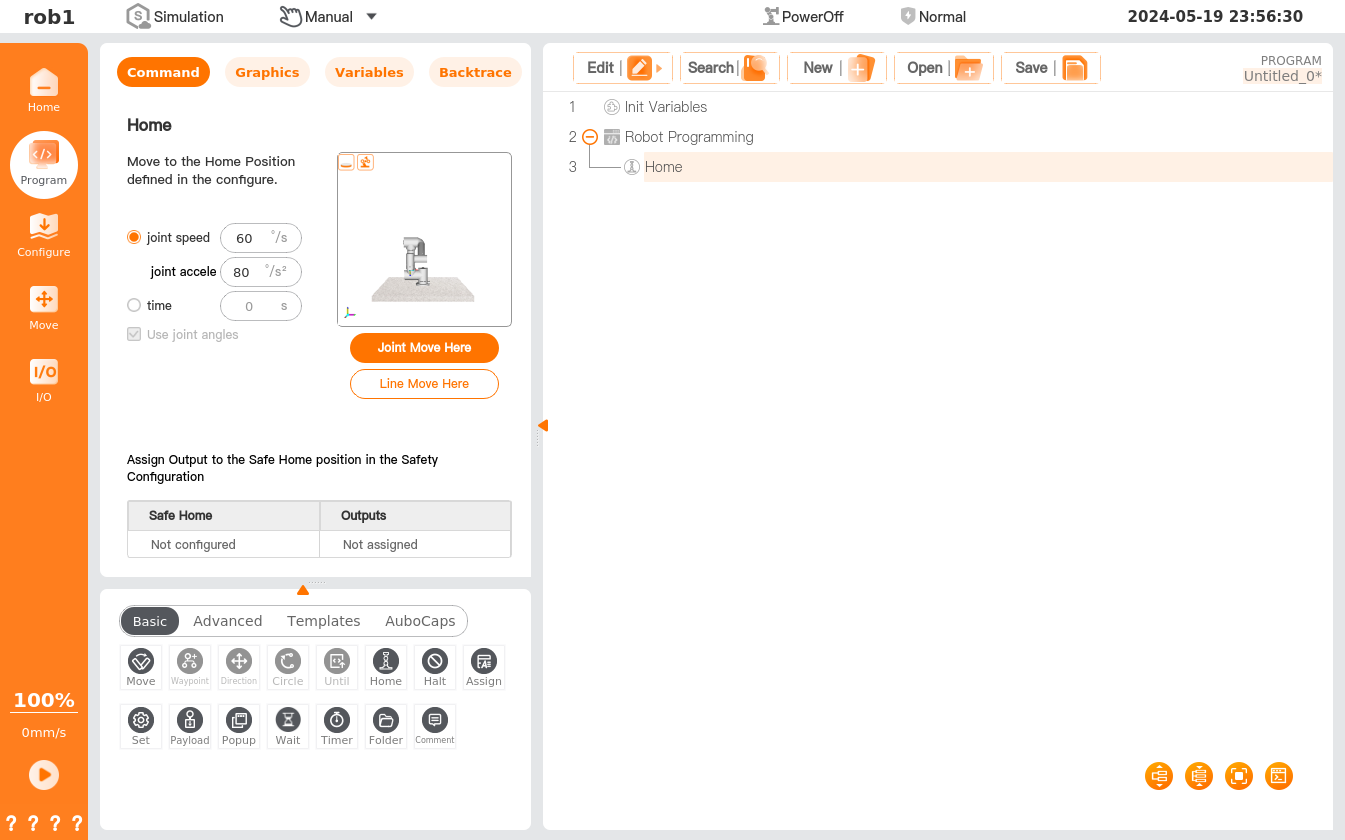
Settings
- MoveJ.
- Joint speed/joint acceleration: You can set the joint speed/joint acceleration for movement to the [Home] position.
- Time: You can set the time for movement to the [Home] position.
- Joint Move Here/Line Move Here: click to access the [Move] interface, and press and hold [Auto] to move the robot to the [Home] position.