General
Home
The [Home] page contains the common positions/poses of the robot, where you can customize the home position/pose or quickly move the robot to the common positions/poses.
- Robot: Allow simulating the current robot status.
- Home: Allow viewing the position/pose parameters of the current "Home," setting the common positions/poses, or controlling the movement of the robot to the common positions/poses.
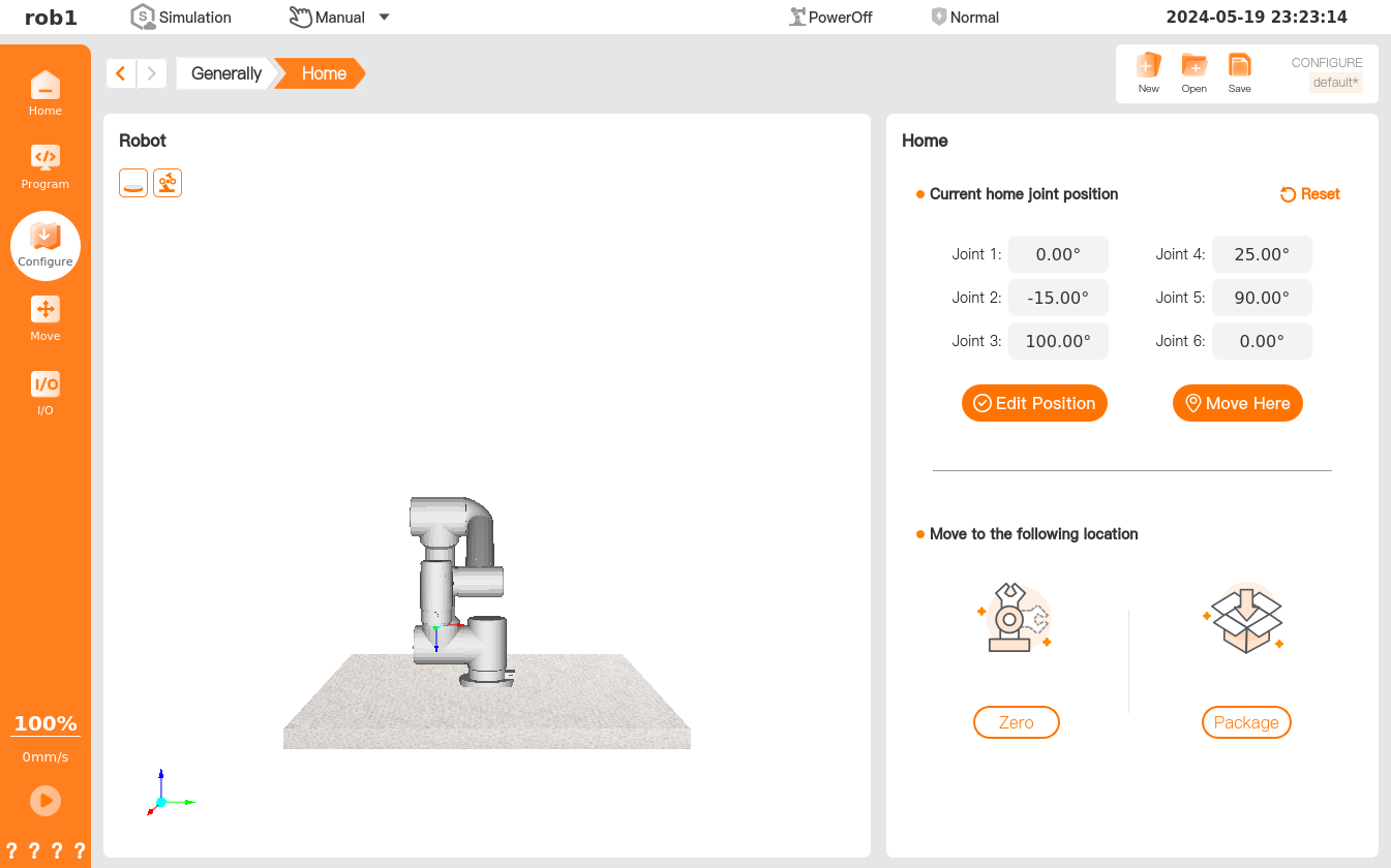
- Edit Position: Edit the user-defined home position/pose. Click [Edit Position] to enter the [Move] page and move the robot to set the position/pose. Click [OK] to save and return.
- Move Here: Move the robot quickly to the home position/pose. Click [Move Here] to quickly enter the [Move] page, where the orange numbers in the joint control box indicate the joint parameters of the current home position/pose. Long press [Home] or [Auto] to move the robot to the home position/pose, and then click [OK] or [Cancel] to return.
- Restore Default: Clear the user-defined home position/pose and restore the default home position/pose.
- Zero: Move the robot quickly to the zero position/pose.
- Package: Move the robot quickly to the packaging position/pose. The packaging position/pose is used when the robot is being packaged for shipment.
I/O setup
For I/O configuration methods, please refer to I/O Configuration, and for an introduction to configurable I/O functions, please refer to I/O Function.
Start
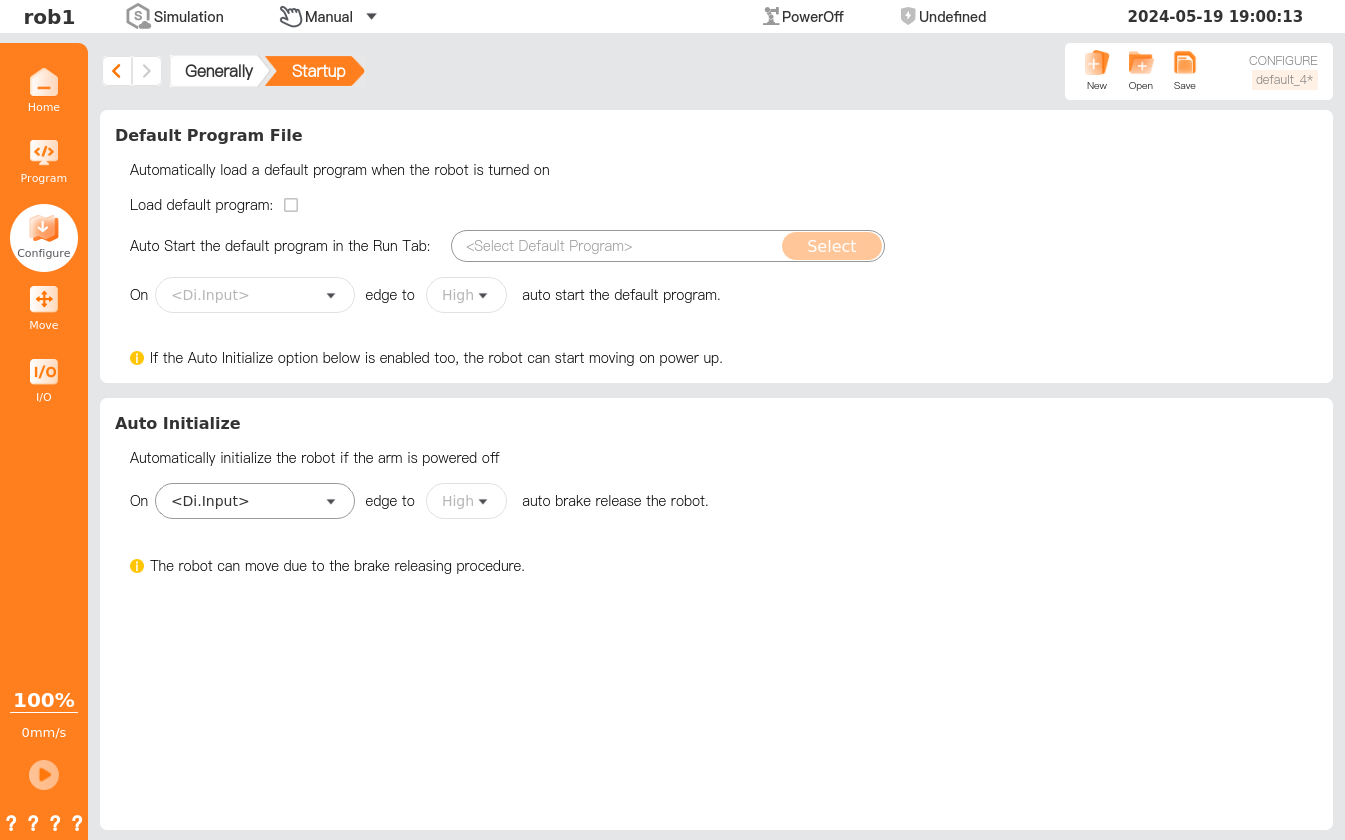
[Start] allows setting of the default program and auto initialization. A default program is a program loaded automatically upon boot of the controller, which is loaded automatically when the system starts running without loading any programs. Auto initialization, i.e., when the robot receives an initialization signal in the power-off state, it will start initialization to restore to the operable status.
Warning
- When automatic robot connection, automatic power-on, and automatic loading are enabled, the robot runs the program immediately after the controller is powered on, provided that the input signal matches the selected signal level. For example, in the case of low level, it is no need to transit an edge level to the selected signal level.
- Be careful when setting the signal level to a low level. The input signal is set at a low level by default, allowing the program to run automatically without interference from external signals.
Tip
Exiting the running program or clicking the "Stop" button in the teach pendant software will disable the auto-start feature until the "Run" button is pressed again.
TCP
Please refer to Basic robot operations - Load and TCP.
Payload
Please refer to Basic robot operations - Load and TCP.
Tool I/O
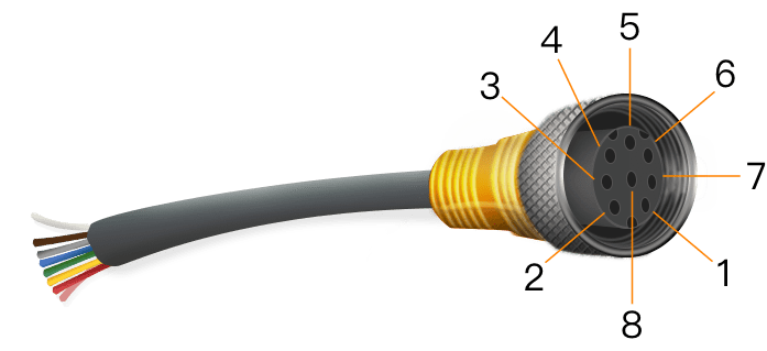
The robot end (joint 6) is equipped with two types of interface: an 8-pin tool I/O interface and a 4-pin tool RS485 interface, which can provide power supply and control signals to end-of-arm tooling (EOAT) (such as a gripper). The end interface configuration may vary for different models; please refer to the actual product and product specifications for details.
Tool I/O interface
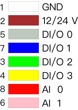
The tool I/O interface is an 8-pin connector, as shown in the figure below. Users can configure 4 channels of digital I/O via pins 3/4/5/7, and configure analog input via pins 6/8, with the analog voltage of 0V ~ 10V; pin 2 can be configured with output voltage of 0 V, 12 V, and 24 V.
[Tool I/O] page allows settings of the EOAT control mode, power voltage and digital I/O communication direction. For the function settings of each I/O interface for EOAT, please refer to “I/O Function.” For the status monitoring of I/O interfaces, please refer to the “I/O Tab.”
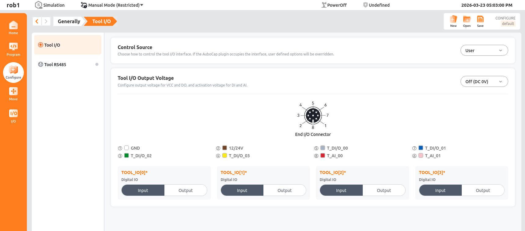
- Control right: Control the switching of tool I/O interfaces.
- Tool I/O output voltage: Set the voltage level (in V) for the tool's digital I/O in output mode. After replacing tools or resetting system, please double-check to ensure that the voltage matches the tool's rated voltage.
- TOOL_IO[0] ~ TOOL_IO[3]: Set the communication direction of the tool's digital I/O.
Tool RS485 interface
After configuring and activating a tool, the system automatically sets the default Tool Center Point (TCP) at the sensor flange based on the sensor dimensions and mounting position. Additionally, the sensor model will be synchronously displayed when showing the robot model.
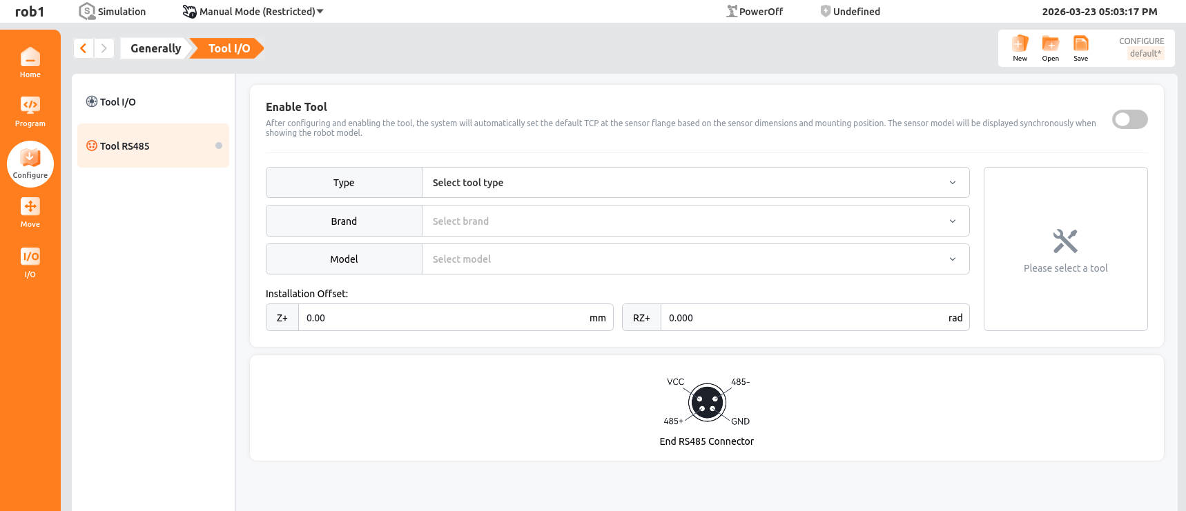
Activate Tool
Fill in the tool parameters, then toggle the button in the upper right corner of the page to activate the sensor.
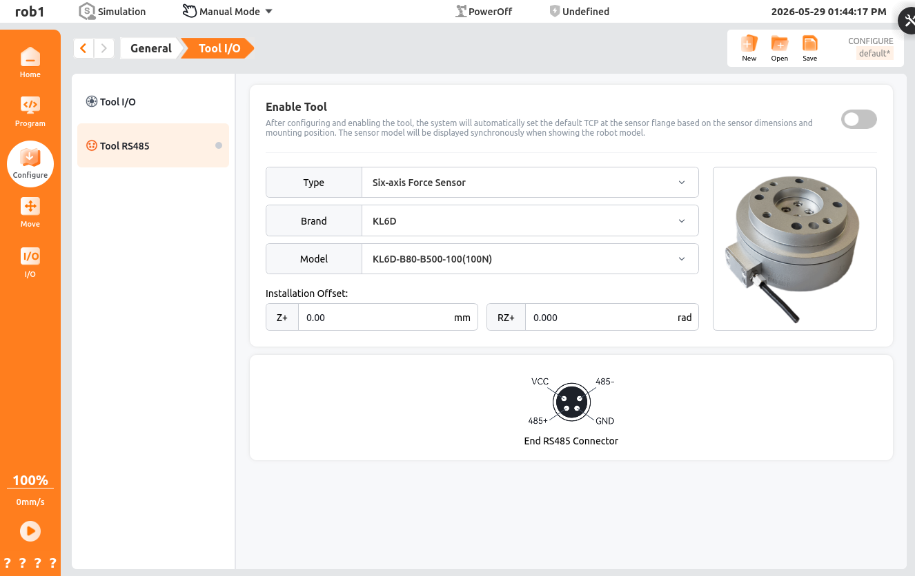
- Type: Select six-axis force sensor.
- Brand: Currently supports Kunwei, Yuhong Minxin, Yuli, Zhili, Keli, Landian, and Xinjingcheng.
- Model: The corresponding model under the selected brand.
- Mounting Offset: Used to compensate for the offset between the sensor coordinate system and the flange coordinate system. Generally 0; currently only Yuli sensors require an offset of 45°.
After toggling the button, the activation status can be identified by the activation indicator light. Upon successful activation, the [Zero Calibration] and [Sensor Debugging] function buttons will appear.
Activation indicator light:
Gray when not activated.
Green when activation is successful.
Red when activation fails.
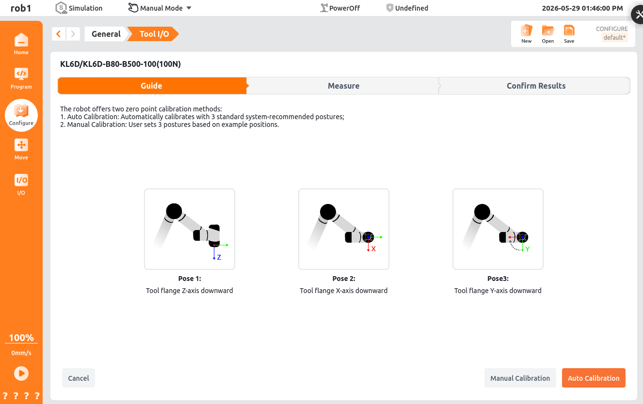
Zero Calibration The zero calibration home page displays the bias from the last calibration. To recalibrate, click the [Recalibrate] button in the lower right corner of the page to enter the recalibration screen. Recalibration includes both manual calibration and automatic calibration functions.
- Automatic calibration: Achieved by autonomously moving to three preset poses; be mindful of potential interference during use.
- Manual calibration: Requires teaching three poses according to prompts, then starting the calibration process.
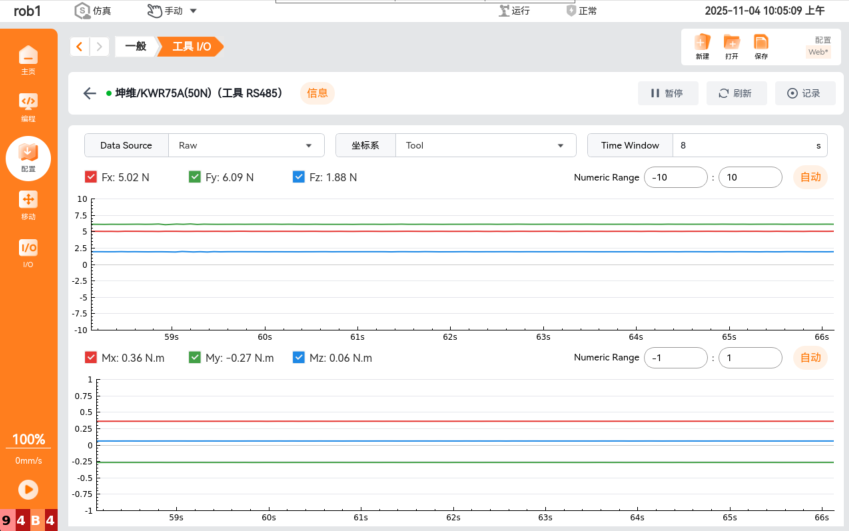
Sensor Debugging The sensor debugging screen is primarily used to view sensor data curves and also provides capabilities for recording data, replaying data, selecting data types and coordinate systems, and setting the data display time.
Variables
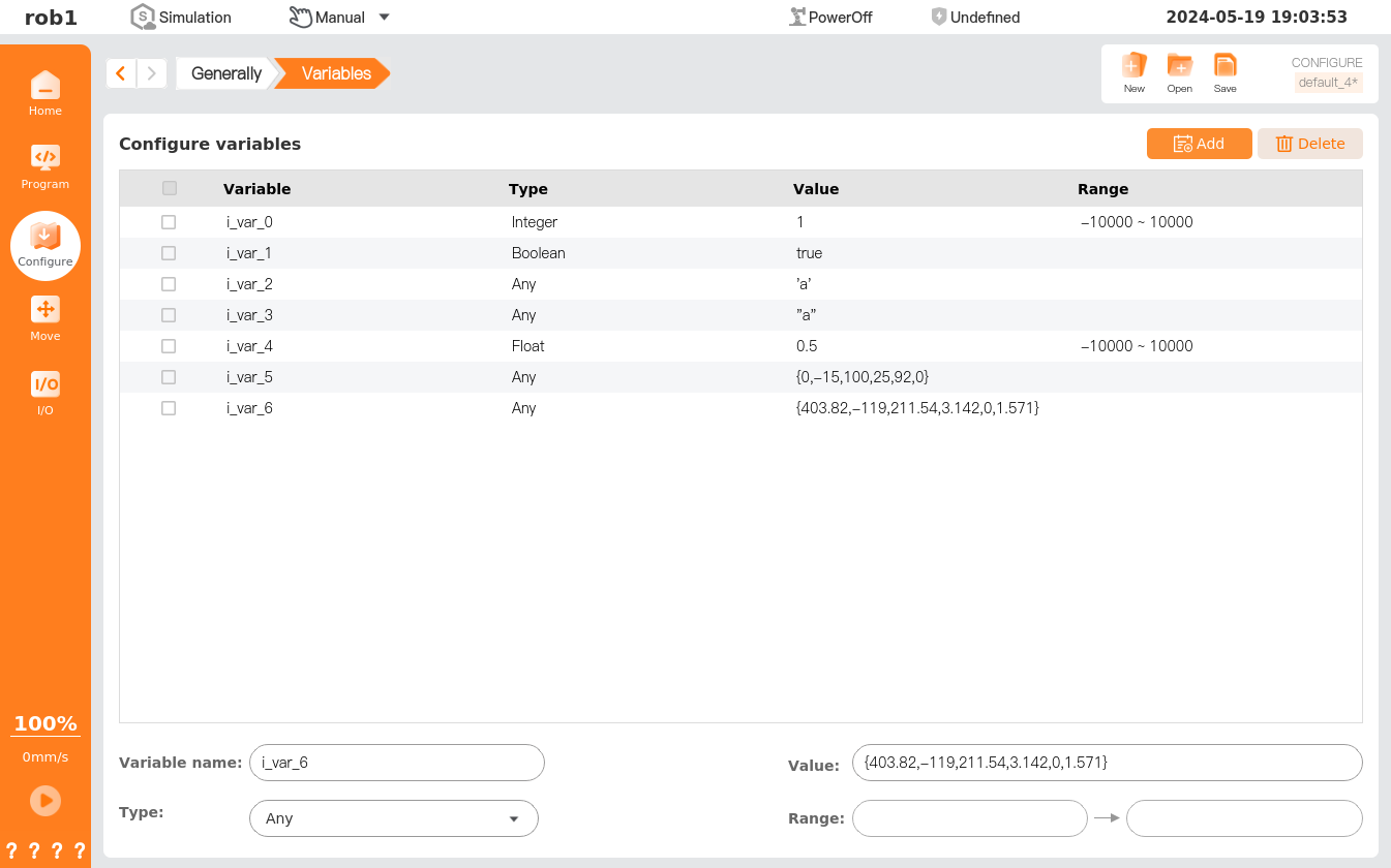
The variables created on this page are called "configure variables," utilized in a manner akin to program variables. They are categorized into five types: Bool, Int, Float, String, and Pose. The difference between a configuration variable and a program variable is that the name and value of the configuration variable are stored in the installation profile, and the user can use the same configuration variables in multiple programs.
The [Variables] page allows the creation of configured variables as well as the setting of their initial values, which can be saved by clicking [Save] on the configuration manager toolbar. In the program running process, the status of configured variables can be updated on this page in real time.
- Global persistence:
1. Types of variables
- Program variables: These variables only apply to the running program, and variable values will be lost after the program stops. They are regular program variables. For details, please refer to "Program tab - Basic program nodes - Assignment."
- Configure variables: Such variables can be applied to more than one program, and their names and values persist until the robot is decommissioned. Therefore, they are persistent variables.
- Script variables: Such variables come from the script file and can be assigned to different variable types. Script variables are not displayed on page [Program] or page [Configure]. They are used by a robot program to store information about the waypoint.
Based on the value treatment mechanism (saved by the system or not) and application scope (one program or more than one program), variables are divided into the following two types:
- Persistent variables: These variables can be applied to more than one program, and their names and values persist until the robot is decommissioned. Values of persistent variables are retained after AuboStudio or the controller is restarted. For example, the configuration variables are of this kind.
- General variables: These variables apply only to the running program, and their values are lost after the program is stopped. For example, the program variables are of this type.
2. Data type
Bool: Boolean variables, whose value is true/false.
Integer: Integer variables, whose value is an integer.
Float: Floating-point variables, whose value is a floating-point number.
String: String variables, whose value is a string value enclosed in single quotes (') or double quotes (").
Pose: Pose variables, whose value is waypoint data containing 6 parameters, as described below:
- In case of MoveL, the first 3 parameters are pose parameters measured in mm, and the last 3 parameters are pose parameters measured in rad.
- In case of MoveJ, all the 6 parameters are joint angles, which are measured in rad.
Record
The [Record] page stores the tracks of robot movement for a period of time, and the stored tracks can be added to the program.
- Simulation model: Simulate robot status.
- Track: Create/Edit/Save/Delete tracks.
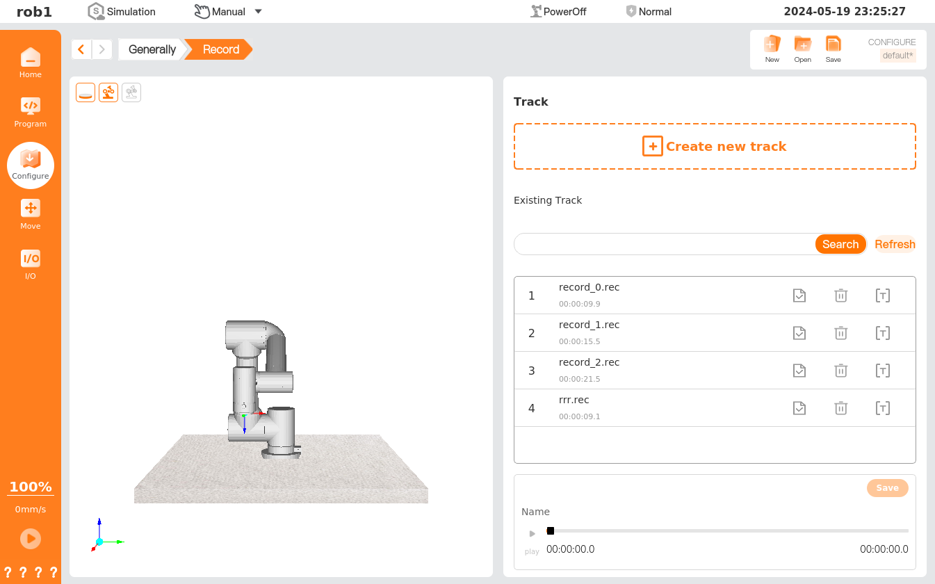
- Create Track: Click [Create Track] to enter the [Move] page, and control the robot using the position/pose control button; then the system will start recording the track of the robot. After the running is completed, click [OK] to name and save the track.
- Search: Search for a certain track by its name.
- Refresh: Refresh the list of tracks.
 Load: Load a track.
 Rename: Rename a track file.
.png) Delete: Delete the track.
Delete: Delete the track. Play: Play the currently loaded track. Click [Play], then enter the [Move] page to move the robot to the initial position, and click [OK] to start playing the moving track. At this time, clicking on [Play] will switch to [Stop] status
  .
.
Create a new track
Click [Create Track] to enter the [Move] page, then click
 to start recording. Control the robot using the position/pose control button. The system will record the robot's track and time. Click
  to exit the [Move] page. After recording, click
  to display a pop-up prompting you to name the track file. After naming, click [Save] to return to the [Record] page.
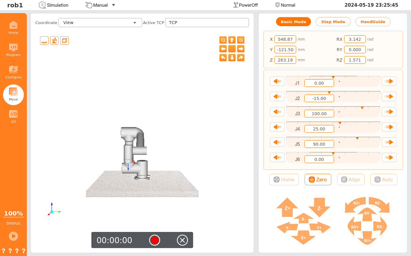
Click
to rename the recorded track.Select the saved track file from the track list and click [Load]
to load the track into the player.
Coordinate system
Please refer to Basic robot operations - Coordinate system.
Drag damping
Please refer to Move teaching - HandGuide - Drag damping.
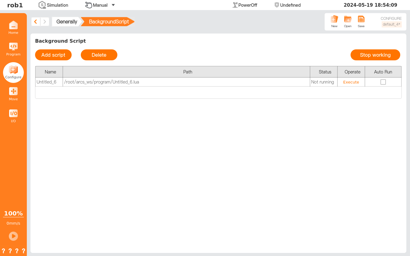
Background script
[Background Script] allows setting of multiple scripts running in the background, tailored to users' needs.
Tip
The scripts added in [Background Script] are not allowed to contain robot motion commands.
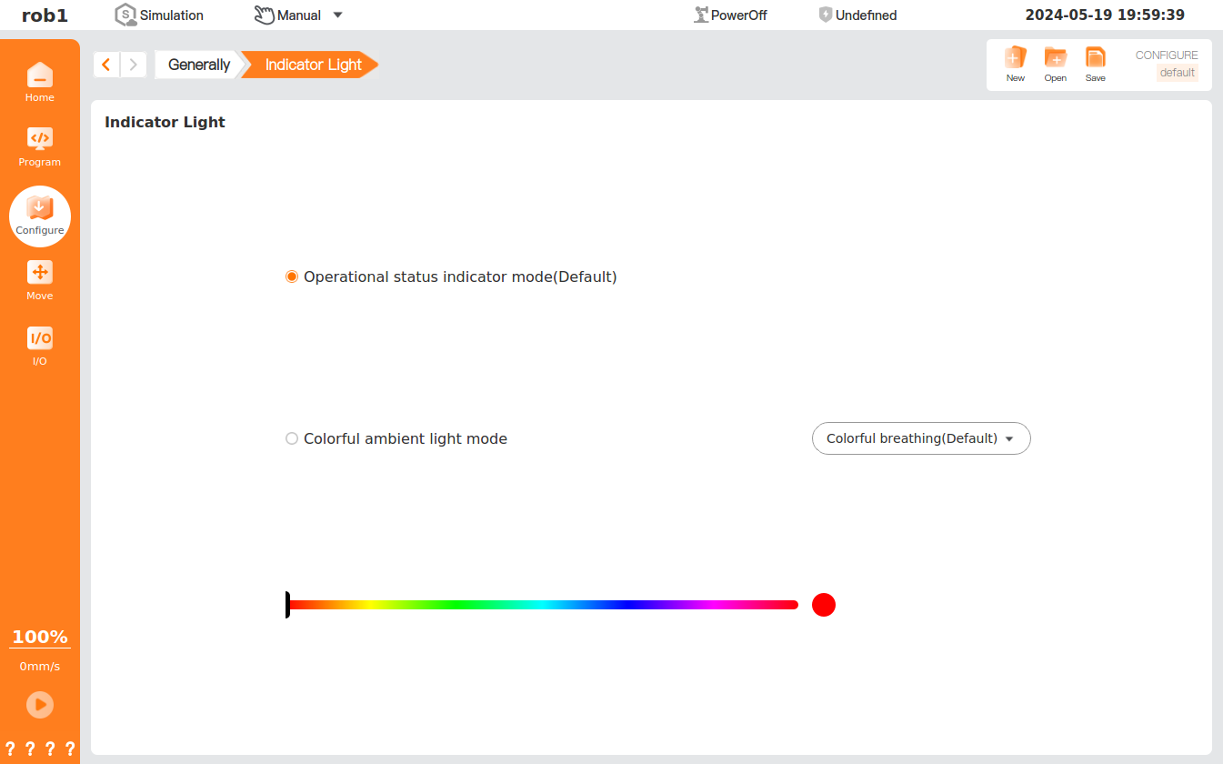
Indicator light*
[Indicator Light] allows setting of the mode of the robot indicator light. This function is only supported by some robot arm models. Please refer to the Hardware User Manual for more details.
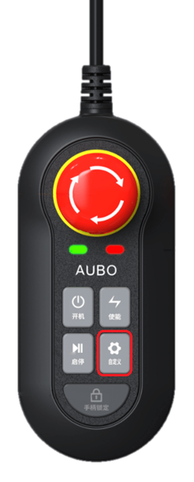
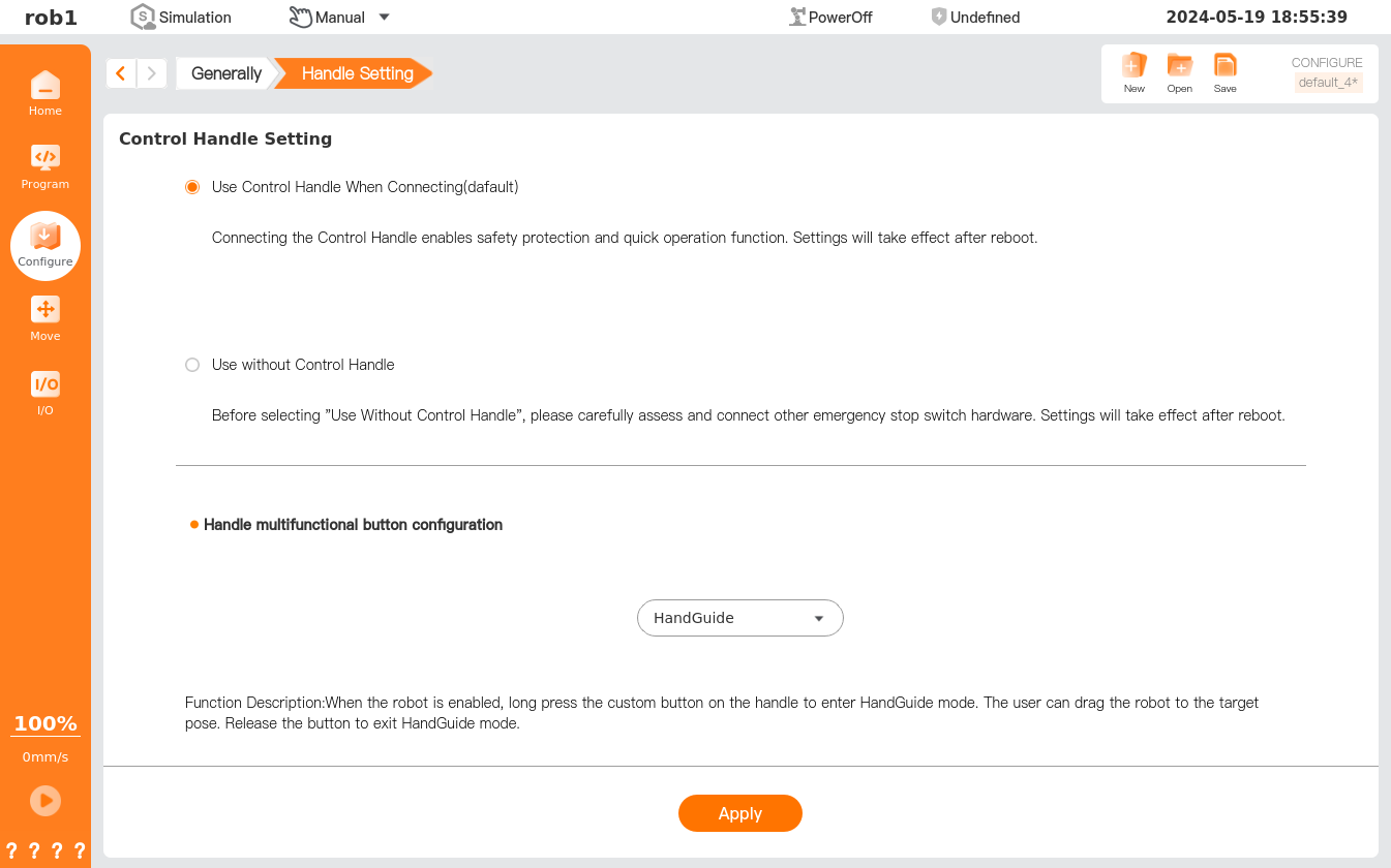
Handle setting*
[Handle Setting] allows setting of the control mode of the handle matched with the product and configuration of the functions of the custom button on the handle. This feature is only supported by some controller models. Please refer to the Hardware User Manual for more details.
Info
Clicking [Apply] will only make the handle settings effective temporarily. To ensure that the relevant settings can be found upon restart, click [Save] to save the current installation profile.
Gripper
The [Gripper] function supports the integration of commonly used electric gripper brands within the software, connecting to the robot arm end or control cabinet via RS485 communication interface, and providing complete configuration and online programming capabilities on the teach pendant.
1. Hardware Connection
Connect the gripper to the robot arm end or control cabinet via the RS485 communication interface.
Note:
Before configuring the gripper, ensure that the gripper is physically connected correctly and the power supply system is functioning properly.
2. Software Configuration
On the teach pendant, navigate to "Configure > General > Gripper" in the left sidebar.
Click [Add] at the bottom left of the gripper configuration page to begin adding a new gripper device.
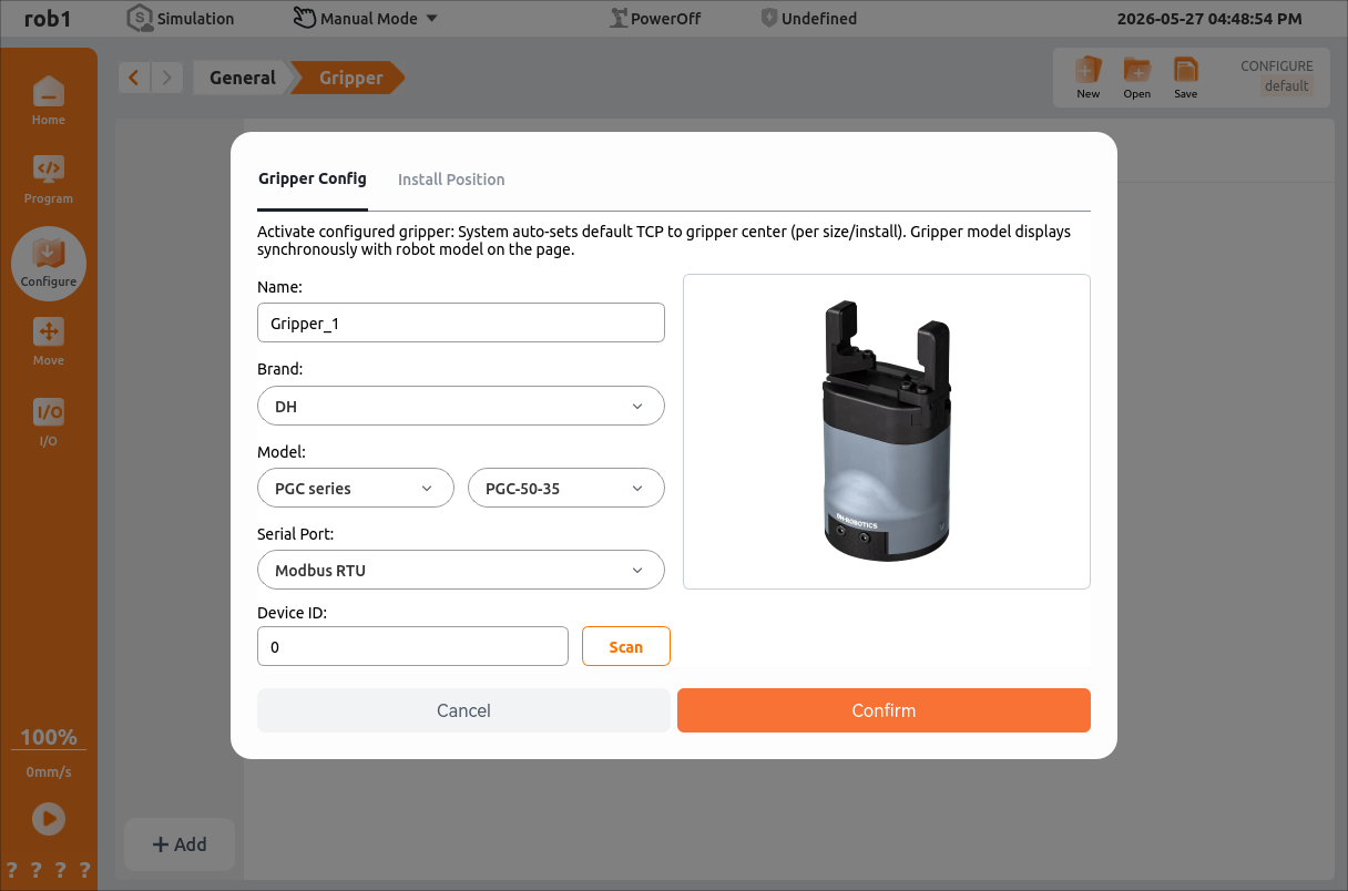
Gripper Configuration
Activate configured gripper: The system will automatically set the default TCP to the gripper center (based on dimensions / mounting), and the gripper model will be synchronously displayed with the robot arm model on the page.
- Name: Gripper name.
- Brand: Gripper brand. Currently supports Da Huan, Rou Chu, and Jun Duo.
- Model: Select the specific gripper model under the corresponding brand.
- Serial Port: Select the communication serial port identified by the system to establish a data connection channel with the gripper.
- Device ID: Unique device identifier.
Mounting Position
- Enable: Used to enable / disable the gripper mounting position configuration function.
- X/Y/Z (mm): Defines the linear offset of the gripper in the robot end flange coordinate system, in millimeters.
- RX/RY/RZ (°): Defines the attitude rotation angle of the gripper in the robot end flange coordinate system, in degrees, corresponding to rotation around the X, Y, and Z axes respectively.
After configuration, click [Confirm] to complete the addition of the new gripper device.
Once the gripper is added, it can be configured.
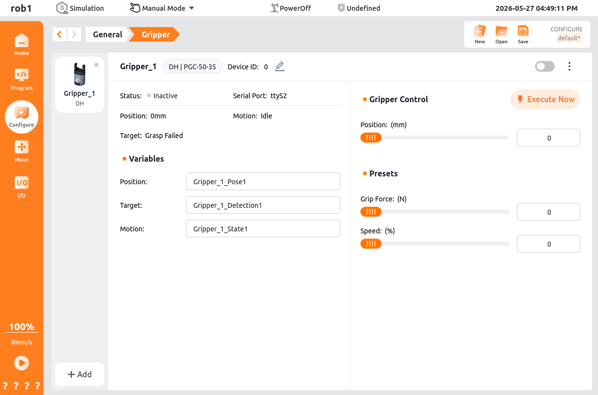
- Gripper Enable Button: Controls whether the gripper is enabled.
- Gripper Information:
- Device ID: The device ID set when adding the gripper, used to distinguish between different grippers in multi-device scenarios; it can be modified.
- Gripper Status:
- Not Started: The gripper is not enabled.
- Normal: The gripper is enabled and functioning normally.
- Communication Fault: The gripper cable connection is incorrect.
- Gripper Fault: The gripper hardware is damaged or functionally defective.
- Gripper Over Temperature: The gripper temperature exceeds 85 °C.
- Gripper Voltage Abnormal: The gripper supply voltage is outside the normal range.
- Gripper Current Abnormal: The gripper supply current is outside the normal range.
- Gripper Enable Failed: The gripper enable process was not completed or the enable conditions are not met.
- Communication Serial Port: The serial port number set when adding the gripper.
- Gripper Position: The current opening / closing position of the gripper, in millimeters (mm).
- Movement Status: The movement status of the gripper, including [Idle] and [Moving].
- Object Detection: The built-in grasping status feedback function of the gripper, which determines whether the gripper has successfully grasped the target object through position closed-loop and current / force control feedback.
- Gripper Control
- Gripper Position: The target displacement for gripper opening and closing, set within the device stroke range (0~26 mm). Once set, the gripper will move to the specified position.
- Parameter Presets
- Gripping Force: The clamping force when the gripper closes, which directly affects grasping stability and workpiece safety. It should be adjusted according to the workpiece material and weight.
- Gripper Speed: The movement speed of gripper opening and closing, expressed as a percentage of the device's maximum speed. Lower values result in smoother motion.
- Variables
- Gripper Position: Retrieves the current position value of the gripper (0-26 mm), which can be used to determine whether the gripper has reached the position.
- Object Detection: Retrieves the result of object detection (Success / Failure), which can be used for grasp logic decisions (e.g., trigger an alarm and retry upon failure).
- Movement Status: Retrieves the movement status of the gripper (Idle / Moving), which can be used for process waiting (e.g., wait for the gripper action to complete before proceeding to the next step).
3. Programming Usage
In the programming tree, click "Templates > Gripper" to add a [Gripper] node.
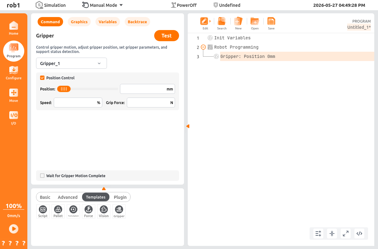
Select the gripper added in [Configuration] and choose whether to enable [Position Control].
Enable [Position Control]:
- Control Logic: The gripper moves to the specified target position and then stops. If the gripping force reaches the set threshold during movement, it will also stop early and determine that the grasp is successful.
- Applicable Scenarios: Standardized grasping where workpiece dimensions are known and a fixed opening is required, or scenarios requiring precise control of the gripper stroke.
- Effective Parameters: Gripper Position (mm), Gripper Speed (%), Gripping Force (N).
Disable [Position Control]:
The gripper will prioritize the set gripping force as the control target, performing force-controlled adaptive grasping.
- Control Logic: The gripper continuously moves in the closing direction until it detects that the set gripping force threshold has been reached (workpiece grasped) or the mechanical limit position is reached, after which it stops. The target position parameter will be ignored.
- Applicable Scenarios: Scenarios with unknown / variable workpiece dimensions, fragile workpieces, or flexible grasping, where position deviation could otherwise cause workpiece damage.
- Effective Parameters: Gripper Speed (%), Gripping Force (N).
Choose whether to enable [Wait for Gripper Motion Complete]
- Enable [Wait for Gripper Motion Complete]
- Control Logic: The robot main program will enter a waiting state and will not execute subsequent instructions until the gripper action has completed (reached the target position / triggered the force control stop condition).
- Applicable Scenarios: Processes such as grasping and placing that require confirmation that the gripper action has completed before moving, to prevent workpiece dropping or program logic confusion.
- Disable [Wait for Gripper Motion Complete]
- Control Logic: The robot main program will not wait for the gripper action to complete and will immediately execute subsequent instructions. The gripper action and robot motion proceed asynchronously in parallel.
- Applicable Scenarios: Scenarios with extremely high cycle time requirements where the gripper action and robot movement do not interfere with each other, improving program execution efficiency.
- Enable [Wait for Gripper Motion Complete]
Run [Test] to move the gripper according to the set parameters.
Collision
The AUBO robot is equipped with protection against excessive external forces; it can detect external forces and take appropriate actions to safeguard itself and prevent damage to the surrounding environment and personnel.
The [Collision] page allows settings of collision level and collision mode, etc. The user can change the collision level and the method for handling a robot collision based on the actual situation to ensure the safety and reliability of the robot in use.
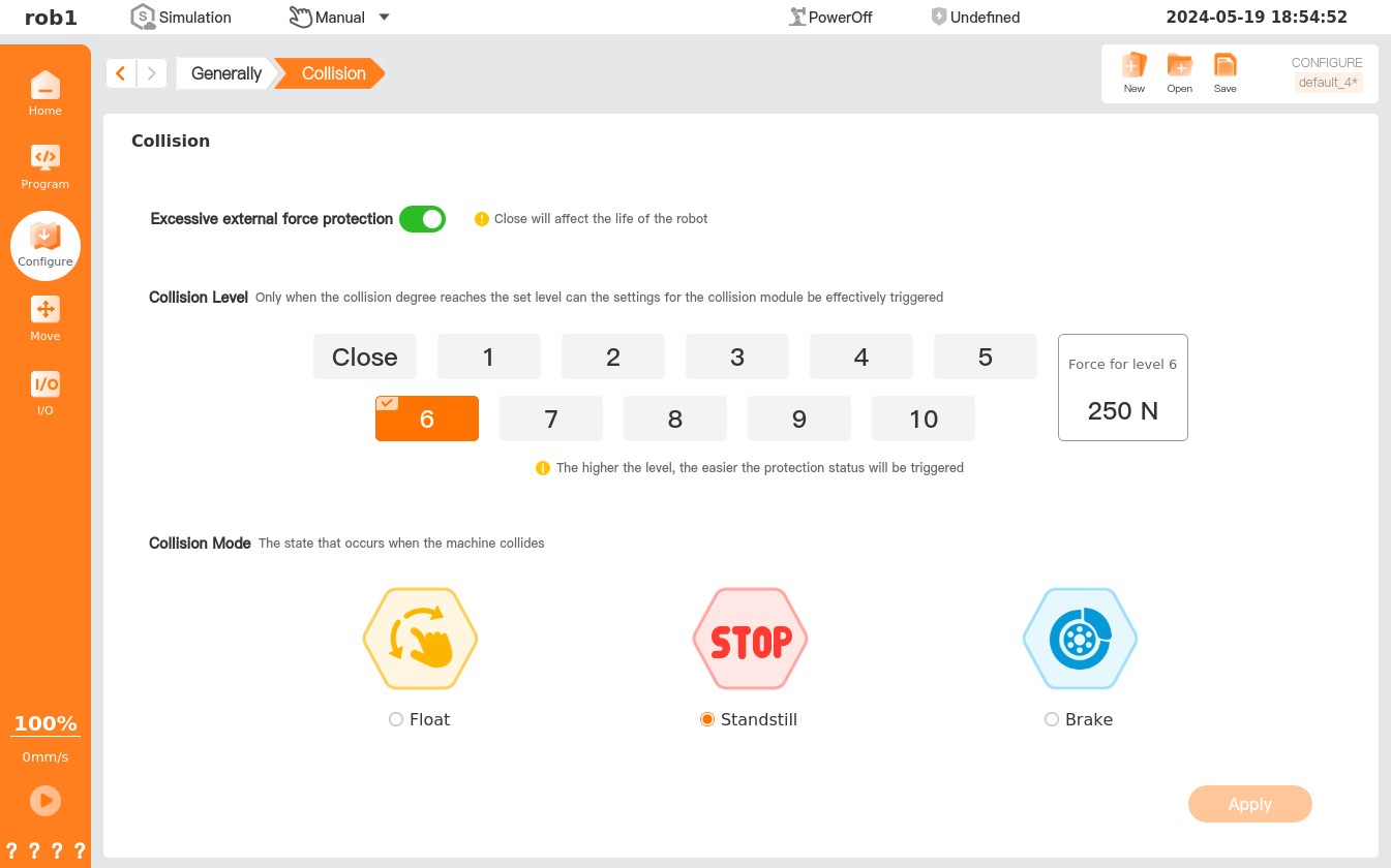
1. Protect against excessive external force
Open: If the robot is in a static state and subjected to an external force that exceeds the safe level judged by the system, the robot will enter the HandGuide mode to prevent damage to critical moving parts.
Close: If the robot is subjected to an excessive external force in the static state, its key actuating components may be damaged, shortening the robot's service life.
2. Collision level
The robot features 10 safety levels that determine the sensitivity of the robot when a collision event is triggered. The lower the value, the higher the safety level, and the more force needed to trigger the collision event. The system default collision level is Level 6.
3. Collision mode
This mode involves how the robot is going to act after a collision event occurs.
- Floating after collision: After a collision, the robot stops and enters the HandGuide mode, allowing the operator to manually drag it to any safe position.
- Quiesce after collision: After a collision, the robot stops and remains stationary.
- Brake engagement after collision: After a collision, the robot stops and remains stationary with the brake engaged (this function is applicable only to robots with firmware version 1.*.*).