Product Introduction
6-Axis Collaborative Robot System Overview
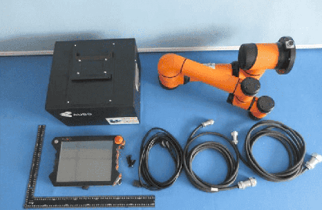
Hardware items required to install and operate a complete robot system:
- Robot arm
- Control cabinet
- Teach pendant
- Robot connection cable
- Teach pendant cable
- Power cord
- Control handle (optional)
Controller
Concept of the control cabinet:
The control cabinet is the control center of the robot. It contains the control mainboard, safety interface board, switching power supply and safety protection components, etc. The cabinet can be powered by 110 V/220 V AC, and its internal switching power supply converts 110 V/220 V AC into 12 V, 24 V and 48 V DC to supply the loads inside the cabinet and the robot. Before use, you must check whether the connections between the robot, the teach pendant and the control cabinet are secure.
The control cabinet provides both hardware and software protection to maximize safety during use. Multiple circuit breakers inside the cabinet provide reliable short-circuit and overload protection at the hardware level, and the emergency stop button on the front panel allows users to cut off robot power in the shortest possible time, protecting both personnel and equipment.
Controller Models
Improved controller
- i-series collaborative products, covering differentiated applications across industries.
iS controller
- iS-series high-performance collaborative products with improved performance, high precision and speed, stronger protection, and a 50% smaller footprint.
- Widely applicable to all industry scenarios, and especially suitable for demanding and sensitive environments such as precision manufacturing and painting.
C controller
- The low-cost C series, a collaborative product developed for the application characteristics of service, new retail and other industries, offering high cost performance and a fast return on investment.
S controller
- Consumer-grade collaborative robot S series, designed for products in the commercial and service fields, with a simple, elegant, deeply lightweight and compact design.
iS Controller
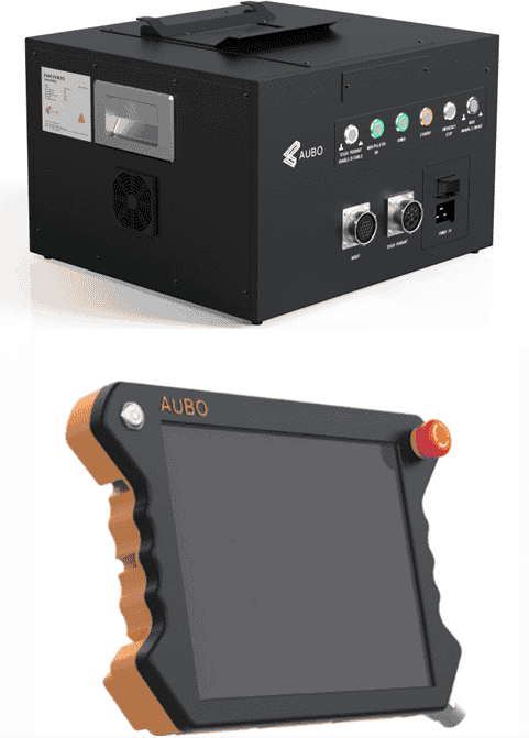
iS Controller - Front Panel
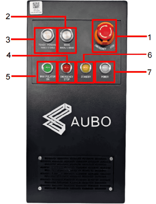
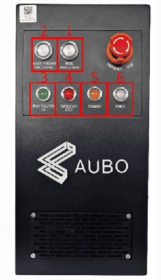
The front panel of the iS controller consists of function buttons and indicators.
EMERGENCY STOP, emergency stop button
● Press the button and the robot immediately enters the safety stop mode.
● Rotate the button in the direction indicated on it to restore the normal mode.
MODE MANUAL/LINKAGE, mode switch button
● Button released: the robot enters manual mode.
● Button pressed: the robot enters linkage mode.
TEACH PENDANT ENABLE/DISABLE, teach pendant button
Press the button to safely unplug the wired teach pendant.
EMERGENCY STOP indicator
When lit, the robot is in the emergency stop state.
MANIPULATOR ON indicator
When lit, the robot arm is powered on.
STANDBY indicator
When lit, the interface board program in the controller has finished initialization, and you can press the power button on the teach pendant to power on the robot.
POWER indicator
When lit, the external power supply is connected.
iS Controller - Rear Panel
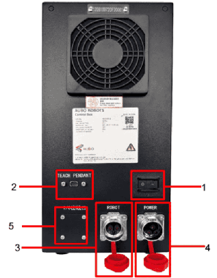
The rear panel of the iS controller consists of the power switch and the cable ports.
Power switch
"I" means on, and "O" means off.
TEACH PENDANT port
Teach pendant cable port, for connecting the teach pendant cable.
ROBOT port
Robot arm cable port, for connecting the robot arm cable.
POWER port
Power cable port, for connecting the power cord.
I/O cable outlet
I/O cable outlet inside the controller
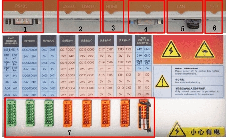
iS Controller - Side Panel
Open the side panel of the controller to access the following electrical interfaces:
- RS485 port
- USB 2.0 and USB 3.0 ports
- HDMI port
- VGA port
- LAN port
- LED indicator
- Electrical interfaces
C-Type Controller
Depending on the application scenario and requirements, the C controller is available in three versions:
- Wireless version
- Wired teach pendant not supported
- Buzzer included
- Wireless AP
- Wired version
- Wired teach pendant supported
- No buzzer
- Wireless AP not supported
- 2-in-1
- Wired teach pendant supported
- No buzzer
- Wireless AP supported
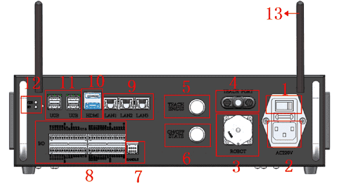
C Controller - Panel
- Power switch
- AC 220 V power input
- ROBOT port
- TEACH PORT (not available on the wireless version)
- TEACH EN/DIS button
- STATE ON/OFF (tri-color operation indicator button)
- Control handle port
- Integrated I/O port
- ETHERNET port
- HDMI port
- USB port
- IPC power indicator
- Wireless antenna
C Controller - NPN and PNP
Introduction
The new C controller provides two I/O configurations: NPN and PNP. Customers can choose whether the I/O is active-high or active-low according to their habits and application scenarios.
Principle
A PNP transistor is a commonly used semiconductor device whose working principle is based on the PN junction characteristics of semiconductors. When a forward bias voltage is applied between the base and the emitter, the transistor conducts and allows current to flow between the collector and the emitter. If there is no voltage between the base and the emitter, or a reverse bias is applied, the transistor is cut off. An NPN transistor works in the opposite way to a PNP transistor.
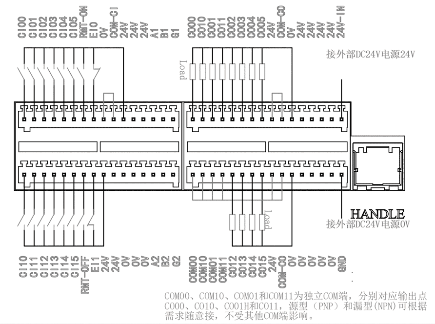
C Controller - PNP Type
Note: The wiring below applies to the PNP configuration only. The common terminals of the NPN configuration are wired differently, so do not apply the PNP connection given here to an NPN controller. Refer to the wiring diagram delivered with the NPN controller, or contact AUBO technical support, before wiring.
- COM-CI connected to 0 V, Cixx connected to 24 V: the input is active;
- COM00 connected to 24 V: output CO00 is active at 0 V;
- COM01 connected to 24 V: output CO10 is active at 0 V;
- COM02 connected to 24 V: output CO01 is active at 0 V;
- COM03 connected to 24 V: output CO11 is active at 0 V;
- COM-CO connected to 24 V: CO02-CO05 and CO12-CO15 are active at 0 V
S-Type Controller
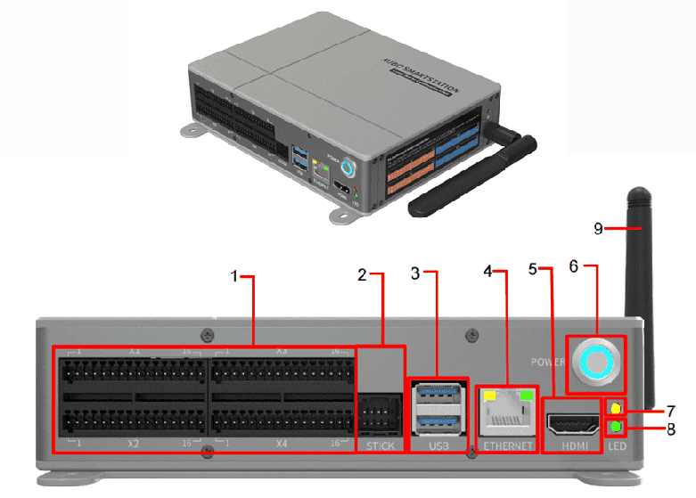
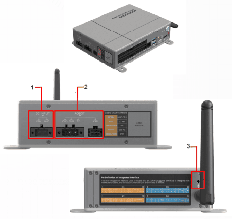
S Controller - Front Panel
- Integrated interface
- Control handle port
- USB port
- ETHERNET port
- HDMI port
- Power on/off button
- Connection indicator Yellow, indicates the connection status of the teaching software. Flashing: the controller is on and the teaching software is not connected. Steady on: the controller is on and the teaching software is connected.
- Power indicator Green, indicates the power state of the controller: Off: the controller is off; Flashing: the controller is on and the robot arm is not powered; Steady on: the controller is on and the robot arm is powered.
- Wireless antenna: plugged into the controller so that a tablet or computer can connect to and control the robot over Wi-Fi.
S Controller - Side Panel
Power input port Connects to the external power supply to power the controller.
Robot arm port Connects to the robot arm.
Grounding screw terminal Insert the grounding screw. For user integration, the controller enclosure or the metal enclosure of the integrated product must be grounded to improve the electrical safety of the system.
S Controller - Device Wiring
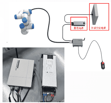
The controller has a built-in DC power supply with a voltage of 24 V and a maximum output current of 2 A, which can supply power to low-power devices (for high-power devices, use an additional power supply for external power).
External power supply and connection cable list:
- Switching power supply
- Robot connection cable
- AC power cord
- DC power cable
- Control handle
Improved Controller
Improved Controller - Front Panel
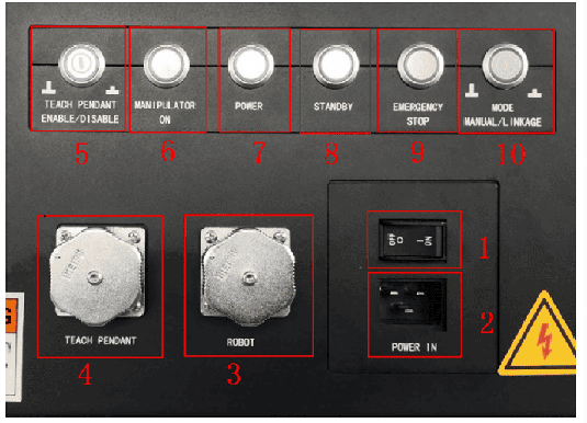
The front panel of the improved controller consists of the power switch, cable ports, indicators and buttons.
- Power switch
- POWER IN port
- ROBOT port
- TEACH PENDANT port
- TEACH PENDANT ENABLE/DISABLE button
- MANIPULATOR ON indicator
- POWER indicator
- STANDBY indicator
- EMERGENCY STOP button
- MODE MANUAL/LINKAGE button
Improved Controller - Top Panel
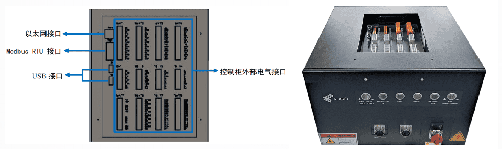
The top panel of the improved controller provides an Ethernet port, USB ports, a Modbus RTU port and external electrical interfaces for the controller.
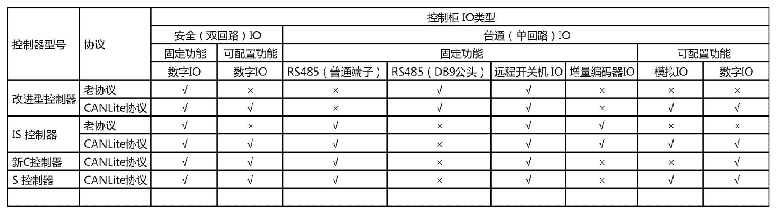
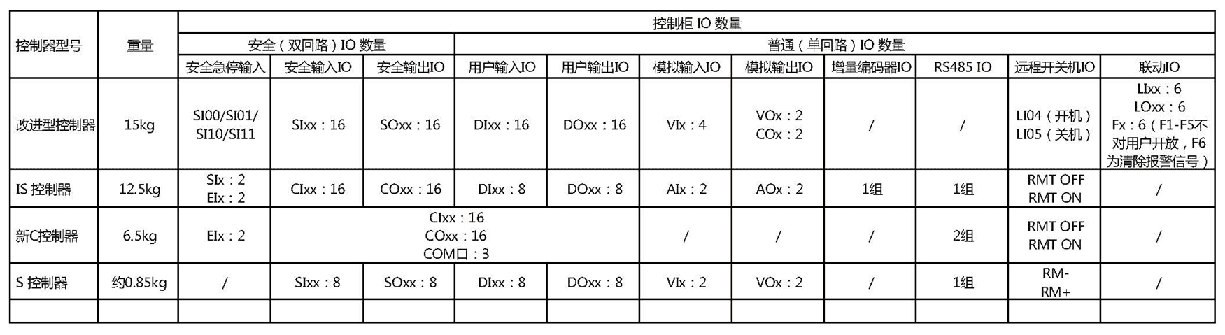
Controller I/O Summary
Controller I/O Summary - Functions
Controller I/O Summary - Quantity
Controller Power-On
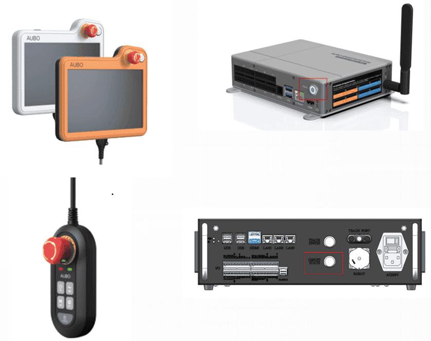
- Power-on buttons
- Power button on the teach pendant
- Power button on the controller (C/S controller)
- Power on with the control handle
- Power on/off button on the handle
- Enable the remote power-on signal
Power-On - Improved Controller
- Power on, turn on the power switch, and the POWER indicator lights up
- Wait for the STANDBY indicator to light up
- Power on the robot
- Method 1: Long-press the power button on the teach pendant to power on the robot.
- Method 2: Connect the remote on/off signal (LI04) to a reset switch, and press the switch to power on the robot.
Power-On - iS Controller
- Power on, turn on the power switch, and the POWER indicator lights up
- Wait for the STANDBY indicator to light up
- Power on the robot
- Method 1: Long-press the power button on the teach pendant to power on the robot.
- Method 2: Connect the remote on/off signal (RMT ON) to a reset switch, and press the switch to power on the robot.
- Method 3: The MODE MANUAL/LINKAGE self-locking button. Press it to power on; press it again to reset and power off (not standard, customized project).
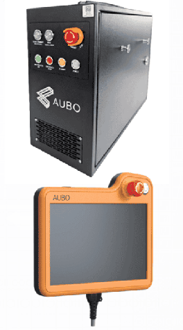
Power-On - iS Controller (Wireless Version)
Power on, turn on the power switch, and the POWER indicator lights up
Wait for the STANDBY indicator to light up
Power on the robot
Method 1: Connect the remote on/off signal (RMT ON) to a reset switch, and press the switch to power on the robot.
Method 2: The MODE MANUAL/LINKAGE self-locking button. Press it to power on; press it again to reset and power off (not standard, customized project).
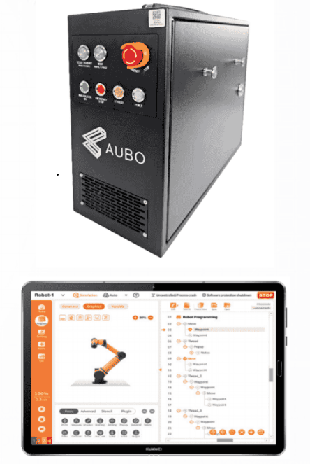
Power-On - C Controller (Wired Version)
Power on, turn on the power switch, and the POWER indicator lights up
Power on the robot
- Method 1: Long-press the tri-color operation indicator button on the controller to power on the robot.
- Method 2: Long-press the power on/off button on the handle for about 2 s to power on the robot.
- Method 3: Connect the remote on/off signal (RMT ON) to a reset switch, and press the switch to power on the robot.
- Method 4: Long-press the power button on the teach pendant to power on the robot (applicable to wired and 2-in-1 versions of the C controller).
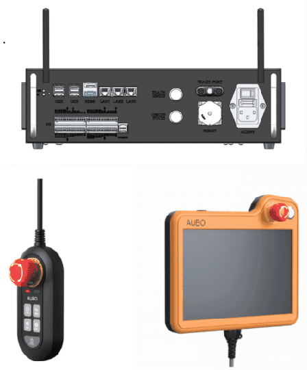
Power-On - C Controller (Wireless Version)
Power on, turn on the power switch, and the POWER indicator lights up
Power on the robot
- Method 1: Long-press the tri-color operation indicator button on the controller to power on the robot.
- Method 2: Long-press the power on/off button on the handle for about 2 s to power on the robot.
- Method 3: Connect the remote on/off signal (RMT ON) to a reset switch, and press the switch to power on the robot.
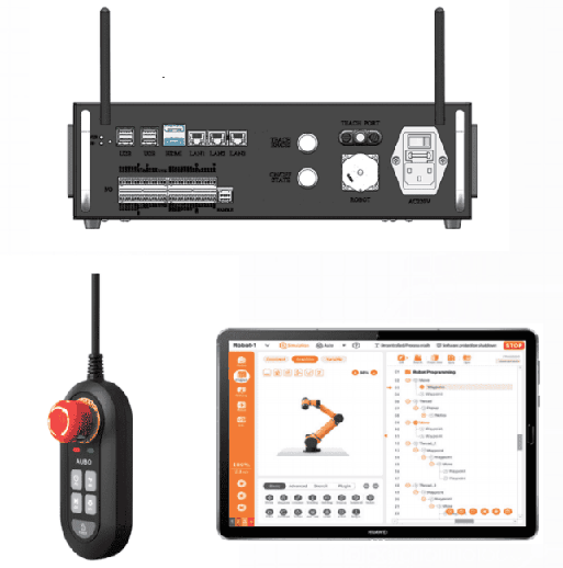
Power-On - S Controller
Power on; the power indicator flashes
Power on the robot
- Method 1: Long-press the power button on the controller to power on the robot.
- Method 2: Long-press the power on/off button on the handle for about 2 s to power on the robot.
- Method 3: Connect the remote on/off signals (RM+, RM-) to a reset switch, and press the switch to power on the robot.
Controller Power-Off
Controller - Normal Power-Off
Normal power-off: after receiving the power-off command, the interface board shuts down the modules in sequence (teach pendant, robot arm, IPC, etc.).
Ways to perform a normal power-off:
- The [Power Off] button in the software interface
- Remote power on/off
- Long-press the power on/off button on the teach pendant for 3 s
- Long-press the power on/off button on the handle for 2 s
- Release the MODE MANUAL/LINKAGE self-locking button to reset and power off (not standard, customized project)
Controller - Forced Power-Off
Forced power-off: after receiving the power-off command, the interface board shuts down the modules in sequence; when shutting down the IPC, it directly issues a hardware shutdown signal.
Ways to perform a forced power-off:
Long-press the power on/off button on the teach pendant for 10 s in any state
Use only for system shutdown in abnormal states.
Long-press the power on/off button on the handle for 10 s in any state
Note: avoid using forced power-off. If a forced power-off is necessary, save any ongoing tasks and files before shutting down, and perform the necessary system checks and maintenance afterwards.
Cut off the power supply directly
Avoid this operation.
Controller Indicators
Controller Status and Events
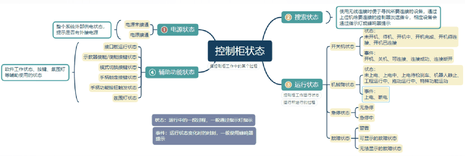
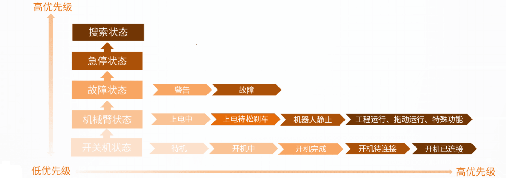
Priority Description
Status priority: under normal conditions, the external power indicator and the auxiliary status indicator are driven independently, while different controllers may use the same indicator for the searching state and the running state, so a priority is required.
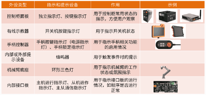
Hardware Peripherals
Hardware peripherals: devices around the controller used for indication and notification, such as indicators and buzzers. Controller peripheral classification:
Hardware Peripheral Example - iS Controller
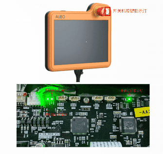
The iS controller hardware peripherals include: the controller panel, the wired teach pendant and the internal interface board.
- Controller panel
- Ring indicator of the MODE MANUAL/LINKAGE button Indicates whether the button is pressed.
- Ring indicator of the TEACH PENDANT ENABLE/DISABLE button Indicates whether the button is pressed.
- MANIPULATOR ON indicator Indicates the running state of the robot arm.
- EMERGENCY STOP indicator Indicates the emergency stop state.
- STANDBY indicator Indicates the power on/off state.
- POWER indicator Indicates the external power status.
- Wired teach pendant
- The ring indicator of the power on/off button indicates the power on/off state of the controller.
- Internal interface board
- Master running indicator Indicates whether the master firmware is running normally.
- Slave running indicator Indicates whether the slave firmware is running normally.
- Master-slave communication indicator Indicates whether the communication between the master and the slave is normal.
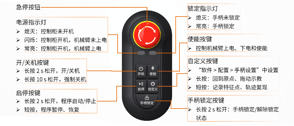
Control Handle
Introduction
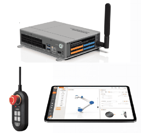
- The control handle allows quick operation of the robot system.
- Magnets on the back of the control handle make it easy to attach.
- Controllers that support the control handle:
- The S controller has a reserved STICK port.
- The C controller has a reserved STICK port.
Button Description