Camera Application
1. Communication introduction
At present, there are two modes for robot arm to communicate with visual device (camera):
The robot arm communicates with the camera via TCP/IP. By adding lua script to the program tree, the camera is triggered to take photos and obtain data. The obtained data type has two meanings:
(1) The robot arm directly obtains the required target location ---- absolute coordinates;
(2) The robot arm obtains the distance to be offset ---- relative coordinates;
The camera is connected to the PLC and is triggered to take a photo. The PLC communicates with the robot arm via communication protocols such as Modbus and Profinet. After the photo is taken, the PLC sends the required offset value to the robot arm, which then performs X, Y, and RZ offsets based on the relative position.
2. ARCS camera communication mode
ARCS can use socket communication to implement TCP/IP communication between the robot and the camera. The AUBO developer website provides relevant examples.
Socket Class Reference | AUBO SDK
-- The example camera uses TCP/IP to communicate, receive photos and send data -- Import to the LuaSocket module local socket = require("socket") -- Set the timeout time (unit: s) local timeout_seconds = 5 -- Encapsulate into a function; transfer parameters: server_ip, server_port, message function send_and_receive(server_ip, server_port, message) -- Create TCP client socket local client = socket.tcp() -- Create TCP socket client:settimeout(timeout_seconds) -- Set the timeout time and prevent blocking -- Try to connect the server local success, err = client:connect(server_ip, server_port) if not success then textmsg("Failure to connect the server:" .. tostring(err)) return nil -- Exit the script directly if the connection fails end textmsg("Connected to the server:" .. server_ip .. ":" .. server_port) -- The content of the message to be sent. Check the communication protocol of the corresponding camera local bytes, send_err = client:send(message .. "\n") -- Add line breaks so that the server recognizes it as a complete line if not bytes then textmsg("Send failed:" .. tostring(send_err)) client:close() textmsg("Disconnected from the server.") return nil else textmsg("Send success:" .. message) end -- Receive the data returned by the server (read by line) local response, recv_err = client:receive("*a") -- *a reads all data, *l reads single line of data if response then textmsg("Received server response:" .. response) -- Judge according to the content if response == "OK" then textmsg("Server confirms receipt of message.") else textmsg("Server returns unknown message.") end else textmsg("Receive failed:" .. tostring(recv_err)) end -- Close the connection client:close() textmsg("Disconnected from the server.") return response -- Return server response end -- Set the server IP and port local server_ip = "192.168.1.100" local server_port = 8080 -- The content of the message to be sent. Check the communication protocol of the corresponding camera local message = "Hello Server" local response = send_and_receive(server_ip, server_port, message) if response then -- Continue processing according to the returned content endUse Modbus master communication, use PLC as a transfer station, send data to PLC, or receive data sent by PLC
Modbus communication reference: 29 Instructions for ARCS Modbus · AUBO Application Notes
Modbus master reads and writes register floating point number.lua
-- Example of modbodbus master reading and writing floating point number
function writeModbusFloat(value, lowSignalName, highSignalName)
    local word = math.float2words(value)
    local low_word = word[1]
    local high_word = word[2]
    modbusSetOutputSignal(highSignalName, high_word)
    modbusSetOutputSignal(lowSignalName, low_word)
end

function readModbusFloat(lowSignalName, highSignalName)
    return math.words2float(modbusGetSignalStatus(lowSignalName), modbusGetSignalStatus(highSignalName))
end

-- Example of Modbus master reading the values of register addresses Modbus_0 and Modbus_14 and assigning them to variable P1. Note that the reading and writing of floating point number requires two register addresses
P1 = readModbusFloat("Modbus_0", "Modbus_1")
-- Example of Modbus master register addresses Modbus_0 and Modbus_1 written to -3.14. Note that the read and write of floating point number need to occupy two register addresses
writeModbusFloat(-3.14, "Modbus_0", "Modbus_1")
Use slave communication (modbus slave and Profinet slave are available), use PLC as a transfer station, send data to PLC, or receive data sent by PLC
Slave reads and writes general register floating point number.lua
-- Slave general register reads and writes floating point number
function writeModbusFloat(value, low, high)
    local word= math.float2words(value)
    local high_word=word[1]
    local low_word=word[2]
    setInt16Register(high, high_word)
    setInt16Register(low, low_word)
end

function readModbusFloat(low, high)
    return math.words2float(getInt16Register(high), getInt16Register(low))
end
-- Example of slave writing general register addresses 300 and 301 to -3.14. Note that the read and write of floating point number need to occupy two general register addresses
writeModbusFloat(-3.14, 0, 1)
-- Example of slave reading the values of general register addresses 300 and 301. Note that the read and write of floating point number need to occupy two general register addresses
P1=readModbusFloat(0, 1)
3. Offset implementation
Offset via custom coordinate system
Reference example: 40 Visual Offset Example · AUBO Application Notes
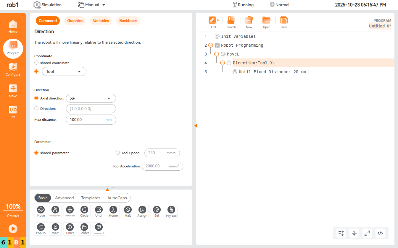
Offset via direction - direct node
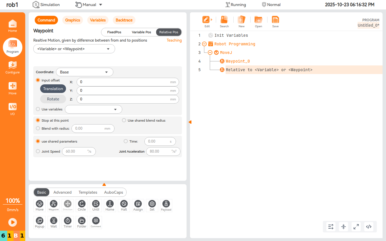
Offset relative to variables or waypoints in the 0.31 branch