Read and Write Profinet Register via Modbus Master
1. Introduction
On the Modbus client page, read and write operations on the Profinet register can be implemented via the Modbus slave general register address. Because the Modbus master was developed earlier, the signal configured by the Modbus master can be used directly as a variable in the programming interface. This method allows users to read and write register more easily.
2. Environment configuration
Profinet version: 0.3.0 and above PLC device: Not required Software version: 0.29.2-beta.30 and above
3. Modbus client configuration
The operation steps are as follows:
Connect the master to the slave, add a
Modbus TCPdevice, modify the IP address to127.0.0.1, and the port is502by default;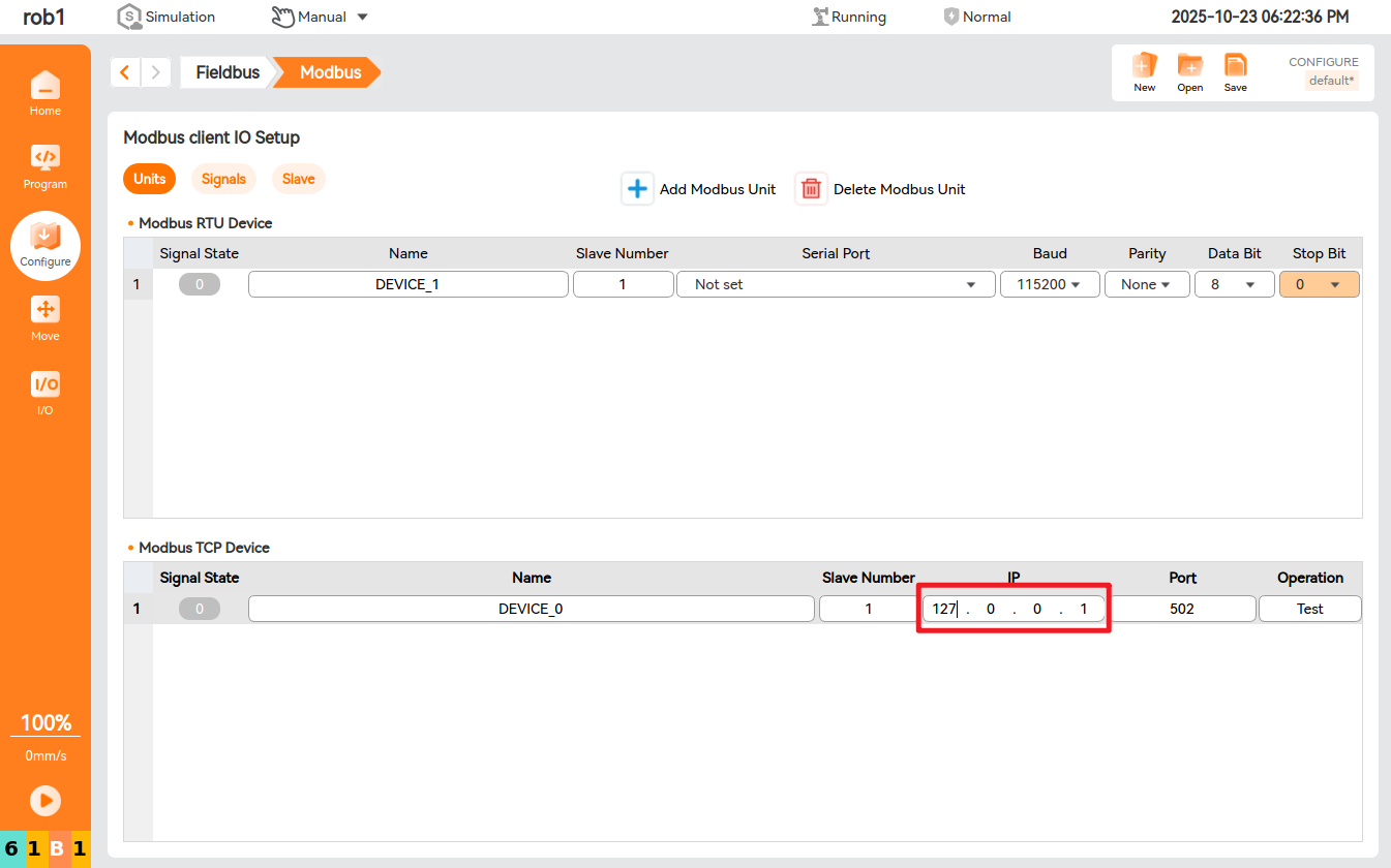
Add the Modbus register output signals in batches, signal address:
300-363;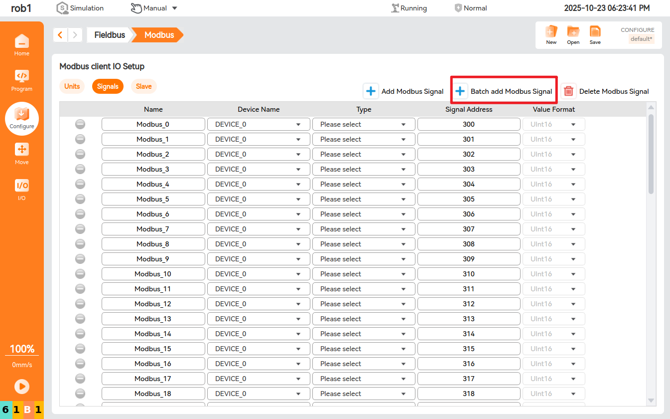
Turn on the
Modbus TCPslave switch, and the port is502by default;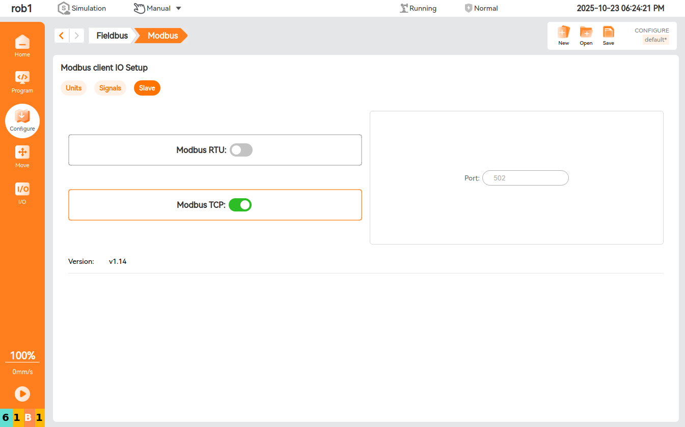
4. Profinet soft configuration
Install the Profinet service. ARCS versions 2025.03 and later have built-in Profinet service and do not require manual installation. Directly go to the Profinet interface and enable the service. The currently installed Profinet version can be seen later. After the Profinet slave and PLC master are connected, the light on the interface will turn from yellow to green.
5. Address lookup
The PLC used here is Siemens S7-200 SMART, which only supports STEP 7-Micro/WIN SMART software.
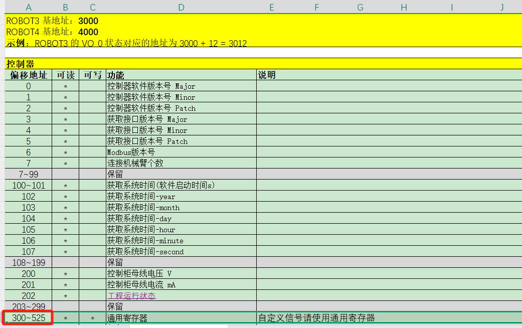
According to the configuration table, the start address of SLOT4 is
128, and the offset of the general register start address is 8 bytes. Therefore, the general register start address of SLOT4 is136, and the corresponding robot general register isint16Register[32].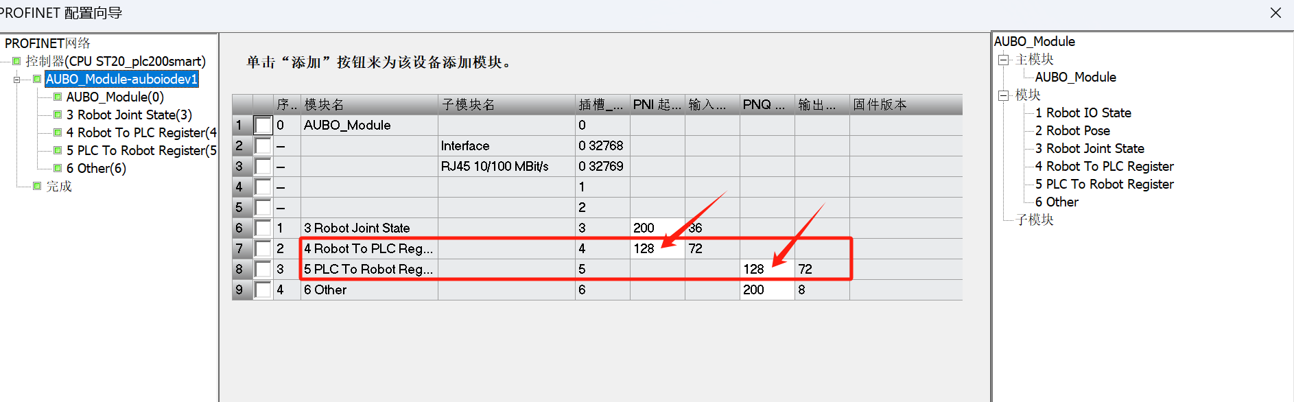
Look up the Modbus slave address table. The general register start address is
300, corresponding toint16Register[0].int16Register[32]corresponds to the modbus332address. There are 32 general registers in SLOT4, and the slave address can be used to control the write of the Profinet register.Modbus slave general register address table:
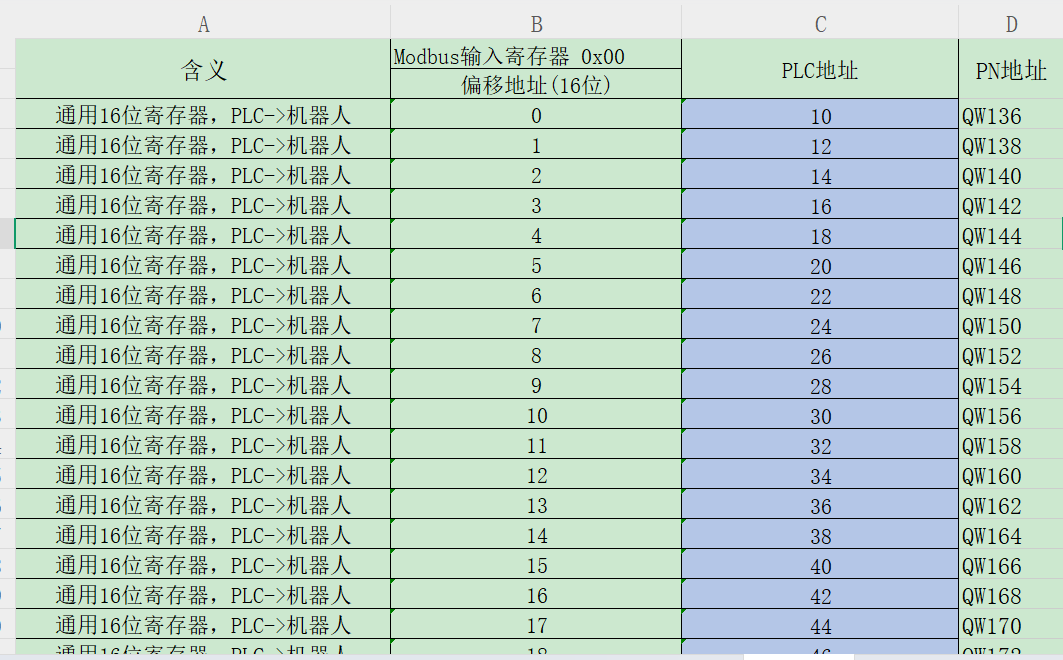
Profinet general register table (PLC -> robot):
Address correspondence table:
Profinet general register address Robot register serial number Modbus slave general register address 1 IW136 int16Register[32] 332 2 IW138 int16Register[33] 333 3 IW139 int16Register[34] 334 ... ... ... ... 32 IW198 int16Register[63] 363 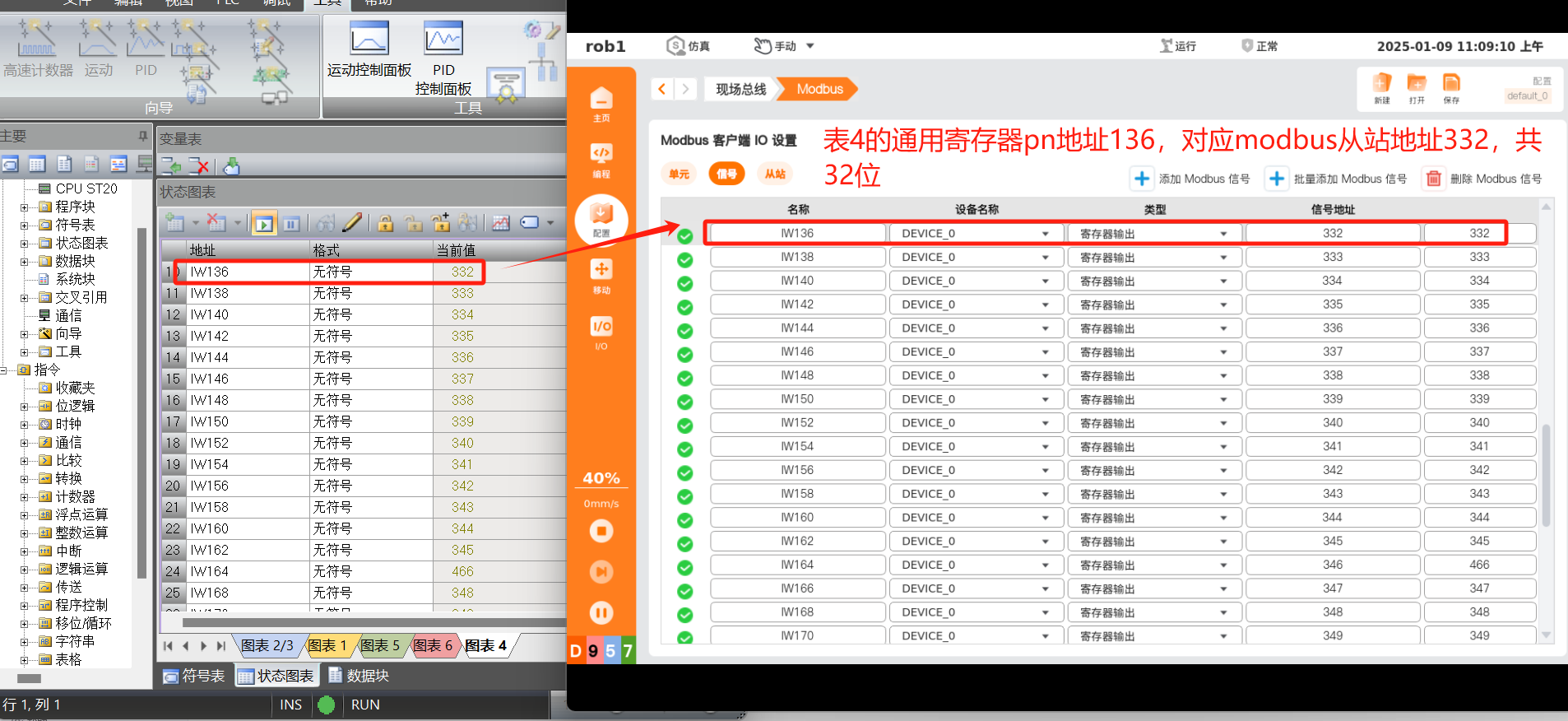
Similarly, according to the configuration table, the start address of SLOT5 is
128, and according to the Profinet address table, the offset of the general register start address is 8 bytes. Therefore, the general register start address of SLOT5 is136, and the corresponding robot general register isint16Register[0]. Look up the Modbus slave address table, the corresponding general register address of the Modbus slave is300-331, a total of 32-bit offset address. The Profinet register address can be monitored through the slave address.Profinet general register table (robot ->PLC):
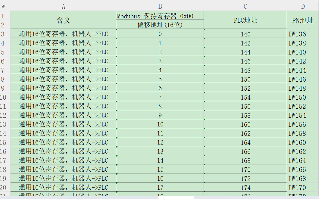
Address correspondence table:
Profinet general register address Robot register serial number Modbus slave general register address 1 QW136 int16Register[0] 300 2 QW138 int16Register[1] 301 3 QW139 int16Register[2] 302 ... ... ... ... 32 QW198 int16Register[31] 331 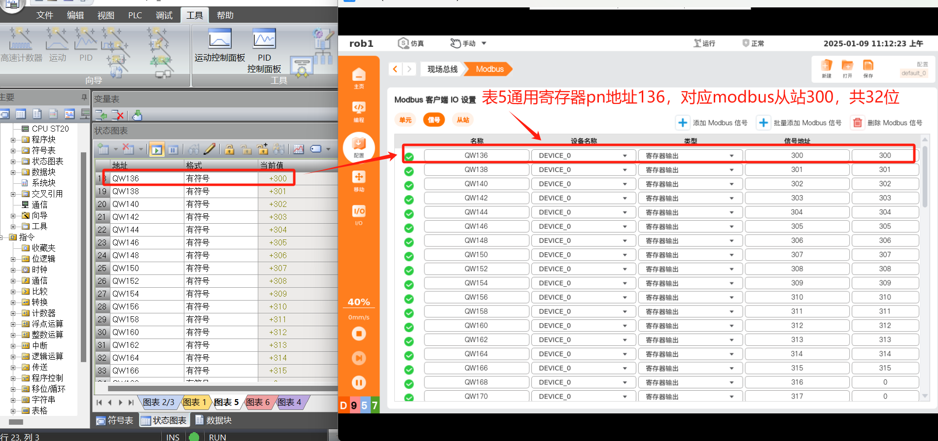
The read and write operations of the Profinet register can be controlled via the Modbus master page.
Example 1: Control the write, and send data
111to PLC via Modbus slave address333; according to monitor addressIW138in PLC monitoring table, the value has changed to111.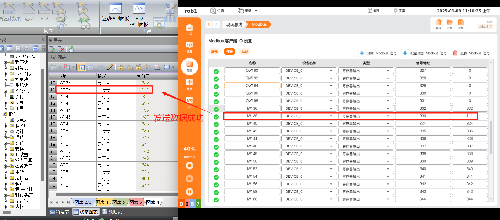
Example 2:
Monitor the read, and PLC sends data
222to the robot via Profinet address136; according to monitor address300in Modbus signal page, the value has changed to222.