
Function Description of IO Points
1. Function Overview
The IO point trigger function is an automated control function that automatically triggers a specified output signal when the joint angles reach the judgment range of a preset point during robot motion. It enables precise coordination between robot motion and external devices or control logic.
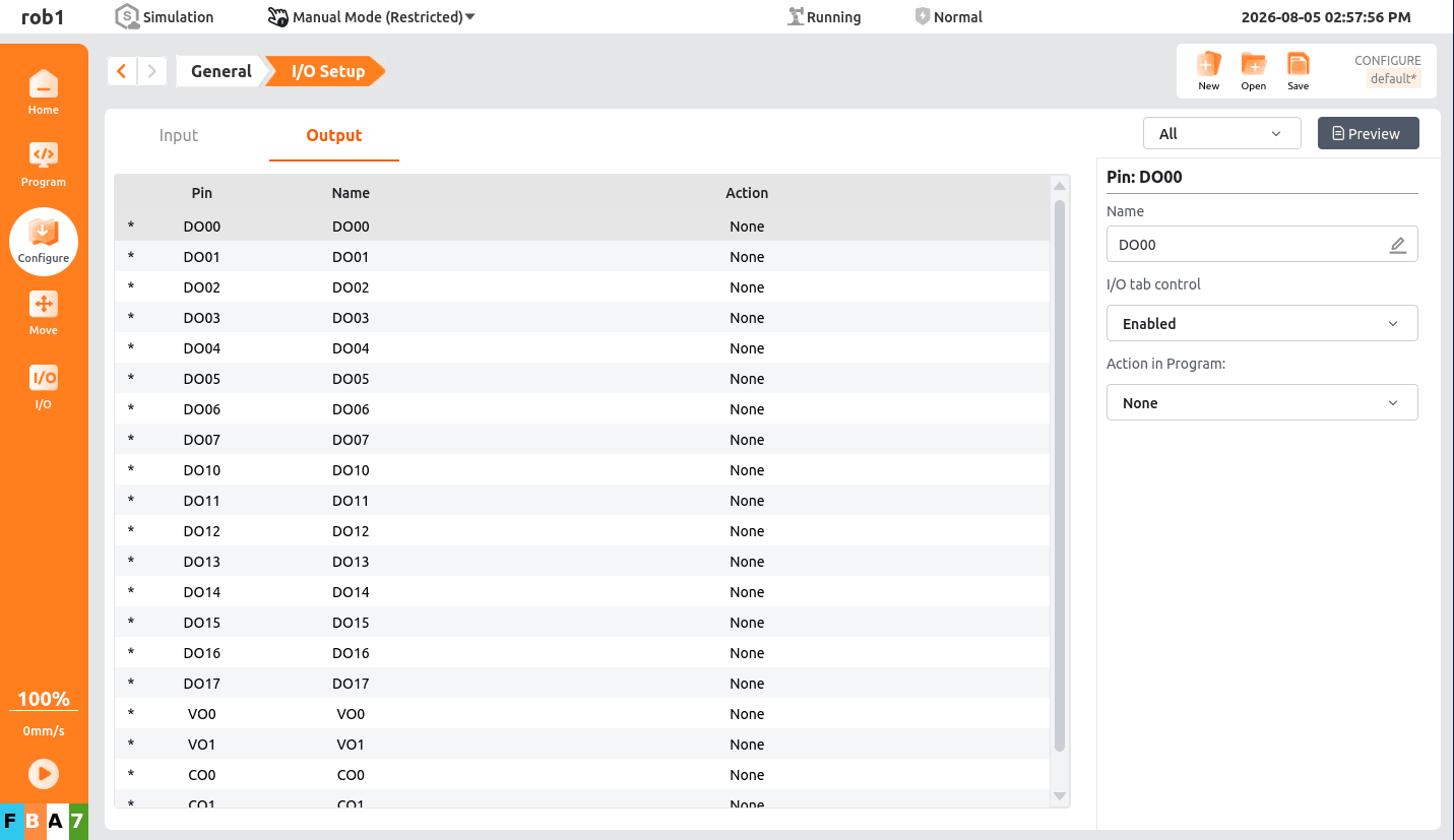
2. Supported IO Signal Types
This function supports only the following four types of output signals. No other signal types are supported:
1. Standard Digital IO Output
Definition: A standard digital IO output refers to a standard digital output on the control cabinet IO panel, for example: DO00.
Applicable scenarios: Standard digital IO outputs are suitable for scenarios where external devices need to be controlled, such as relays and lights. By setting the state of the standard digital output (high level or low level), switching control of external devices can be implemented.
2. Configurable Digital IO Output
Definition: A configurable digital IO output refers to an output interface whose state (high level or low level) can be set through programming, for example: CO00.
Applicable scenarios: Coordination with external devices that require flexible IO characteristic configuration.
3. Tool IO Output
Definition: Tool IO output refers to control signals provided by the robot end tool through its 8-pin connector, for example: TOOL_IO[0].
Applicable scenarios: End-effector control (such as tool grippers and end sensors).
4. Modbus Output Signal
Definition: An output signal based on the Modbus communication protocol, for example: Modbus_0.
Applicable scenarios: Communication coordination with external PLCs and third-party devices.
3. Core Working Principle
Point preset: Configure the target point in the control system and define the joint angle parameters.
Trigger binding: Bind the target point to the above four types of output signals and set the judgment threshold (the allowable angular error range).
Real-time judgment: When the robot is moving, the system compares the difference between the current posture and the preset point in real time.
Signal triggering:
When the difference ≤ the judgment threshold → the output signal is set (ON/high level).
When the difference > the judgment threshold → the output signal is reset (OFF/low level).
State retention: The signal state is synchronized with the robot posture in real time, with no delay and no loss.
4. Core Parameter Description
| Parameter Name | Description | Constraints |
|---|---|---|
| Target point | Preset robot target point | Must be a legally configured point in the system |
| Signal type | Fixed as: standard digital IO/configurable digital IO/tool IO/Modbus output | Analog quantities, pulse quantities, and other signal types are not supported |
| Signal index | Corresponding IO port number/Modbus signal address | Must be within the range supported by the hardware/protocol |
| Judgment threshold | Allowable error range for point triggering (unit: °) | Only values from 1 to 5 are supported |
5. Function Features
Precise triggering: Real-time calculation based on joint angles, with triggering error ≤ the minimum system resolution.
Dedicated types: Supports only digital IO outputs and Modbus output signals. No other signal types are supported.
Real-time synchronization: The signal state is linked with the robot posture in real time, with no delay in switching response.
Exception safety: If the point does not exist, parameters are invalid, or the signal is abnormal, triggering is automatically disabled and the default low level is maintained.
6. Usage Restrictions
Only output signals are supported. IO input signals and Modbus input signal triggering are not supported.
Negative judgment thresholds are not supported. Invalid parameters will be intercepted or ignored by the system.
Unconfigured points and nonexistent IO ports/Modbus signals cannot be bound.
When the robot is in emergency stop or fault state, all point trigger signals are reset immediately.
7. Typical Application Scenarios
The robot moves to a safe position → triggers a standard digital IO to turn on the device indicator light.
The robot reaches the loading position → triggers a Modbus signal to notify the PLC to start feeding.
The robot leaves a path point → triggers a configurable digital IO to close an external solenoid valve.